Process
Introduction
As an introduction to the development of my final project, I would like to emphasize that the idea of what I am giving birth to and what I am developing is very similar, it only varies in that I have reduced the number of lights to make, I want to make two lights to only make the rear light.
This idea can be seen developed in the assignment of principles and practices, specifically in idea 3.
To explain the process that I have followed in my project I have divided this into sections. Each section is a manufacturing process or a different topic within the schedule given in the fabacademy. Below you can see the developments and progress made in each part:
Project evolution
the initial project consisted of a set of two lights for a bicycle, a rear one that received the distance of the cars and that also indicated the distance to which they were and then a front light in which with other indicator lights and an interactive screen , the user of the bicycle received these distances and also had an endless number of other utilities. This first idea can be seen in the assignments of principles and practices and computer-aided design.
This first initial idea is also part of the first spiral of the development of two other projects around the FabBike bicycle that appear in the first assignment.
With the development of the fabacademy and the passage of time I realized that the idea I had for the first spiral was already very ambitious and that this first spiral had to be divided into two, back light and front light of the bicycle.
With this division of the first spiral I had to decide which of the two to take and develop for the final project, this decision I had to take more or less when 3/4 of the time of the fabacademy had already passed. Therefore, there was not much time left.
I reconsidered and ordered these two subspirals by degree of difficulty and I realized that the front light was much more ambitious than the rear light. Therefore I prefer to make the rear light.
From the back light I extracted as a conclusion that the input was sure that I was going to measure the distance to which the cars were and the output I had to deliverate since I wanted lighting and sound but I had to settle for the light since I did not have very clear that the sound signals were allowed.
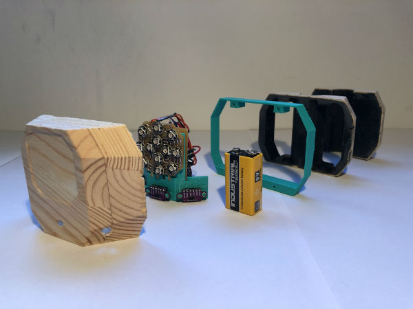
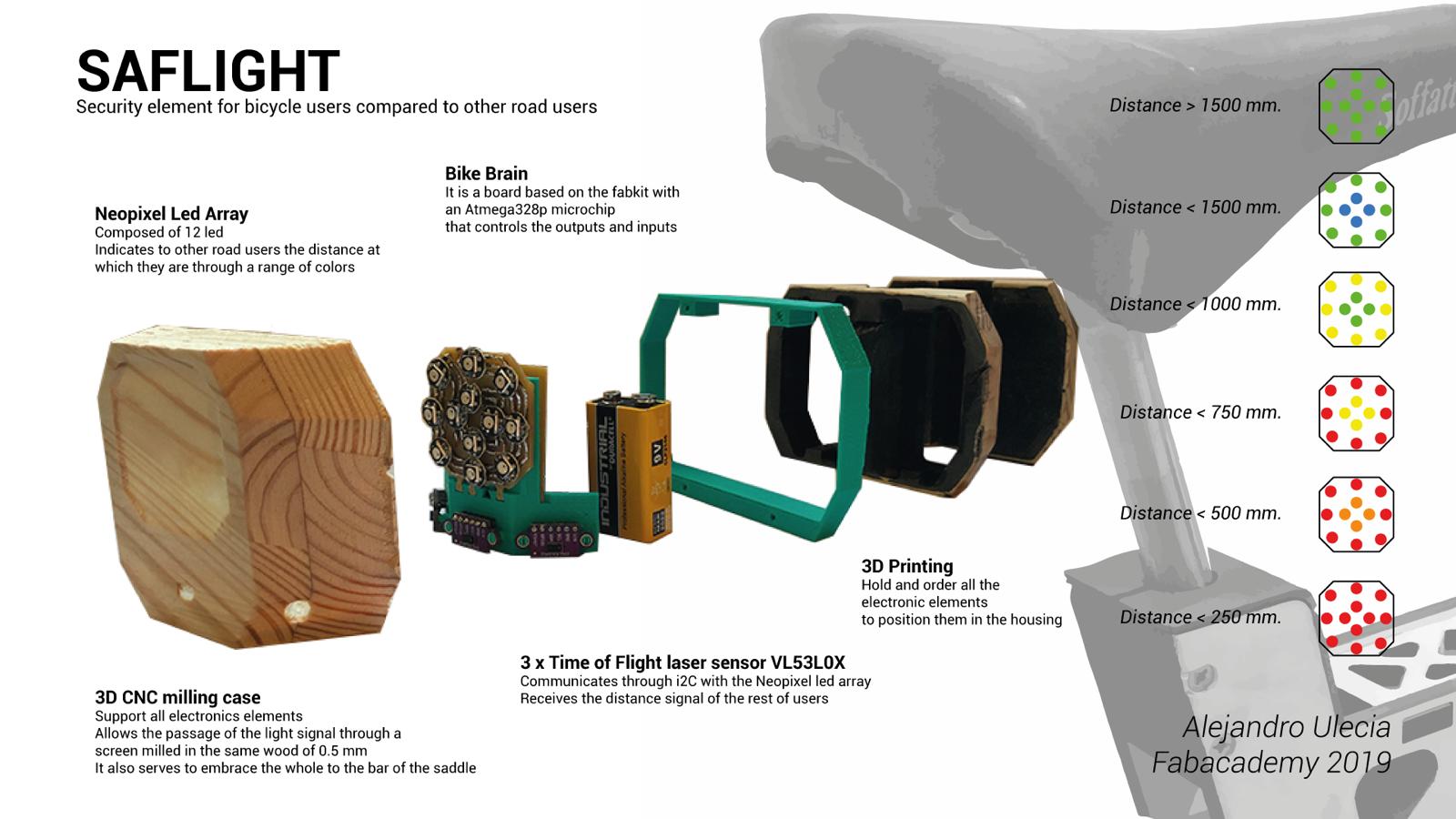
Then the final project was finally defined as a bicycle rear light with an array of neopixels as output and three distance laser sensors as input whose main purpose is to detect the distance of the cars from the bicycle and to indicate to them at a distance to the that are found.
CAD design
This part of the project I started to develop from the beginning of the fabacademy, in the week of the assignment of computer-aided design, in which I developed both the front and the back light. By visiting the assignment you can observe the whole process and how is the initial idea.
For my final project I have decided to design only the back light, I start from the base I made in the CAD assignment but modifying all the measurements and adding more parts due to the complexity of the whole. I used CATIA for the design of all the elements.
I started designing the support that would house the electronics, the sensors (input) and the neopixel led array (output). this has a comb shape in which the three laser sensors placed at 45 degrees each other are incorporated. To hold them I designed a retractable circular clamp on the piece that serves as support for these.
This same piece has a tongue and groove for the neopixel array plate and a rear rail to fit the electronics of the set.
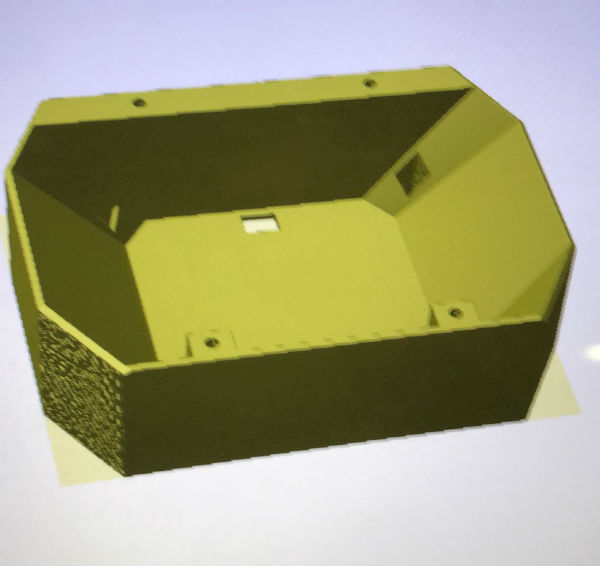
 Once the interior part is designed, go on to design the whole external part through different covers in which to lodge the different parts, in the first one the whole electronics will be housed and the part of the fine milling of 0.5 mm that will let the light pass . It also has 3 holes through which the laser will come out and fulfill its function.
The next cover will be an intermediate that allows to give hollow to the battery and the rear part of the electronics and also embraces the half of the tube of the saddle.
And finally the back cover that will hug the other half of the seat tube and also close the whole. All the covers will be perforated to be able to close them with 4 M3 screws.
After the manufacture of the three pieces and the assembly, I realized that I needed a little more space and I had to design an intermediate piece that I would print in 3D so that the electronics would not be so just inside the set.
n the following video you can see how is the design of all the elements:
3D printing
For 3D printing I used the anet a8 printer that I have in my house, with PLA material and following the functions for the program I used in the 3D scanning and printing assignment.
I have only used this manufacturing process to make two of my final project pieces, one of them is the most important of my project since it is the comb that joins all the electronic elements and also incorporates these to the housing that close the set.
The other piece is the one that I had to make urgently to be able to incorporate everything, it is a separator between the lid 1 and the lid 2 that gives 10 mm. more thickness to the set and that we can observe as it is printed next:
CNC machining
This part of the project has been the most complicated in terms of manufacturing since milling 3 wooden caps in 3 dimensions on both sides is not something we have seen before.
To carry out this task I have supported myself in the following assignments: computer controlled machining, molding and casting and wildcard week, in which I have used this manufacturing method and the programs for this type of actions.
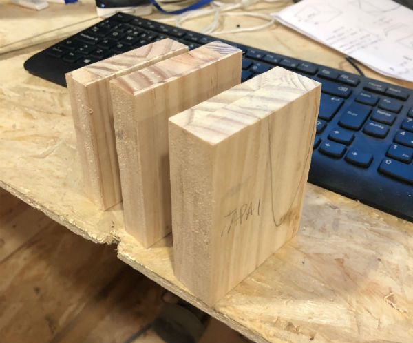
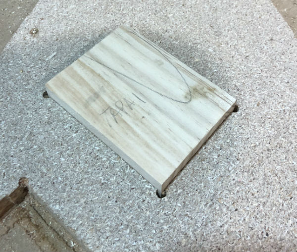
The first thing I did was paste the recycled wood since I did not have wood with enough thickness to get the final pieces, this I did with wood glue and let it dry for 24 hours.
Then screw the dowels to the milling table to reduce the thickness and cut them to the measurements of the end caps.
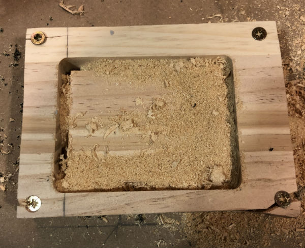
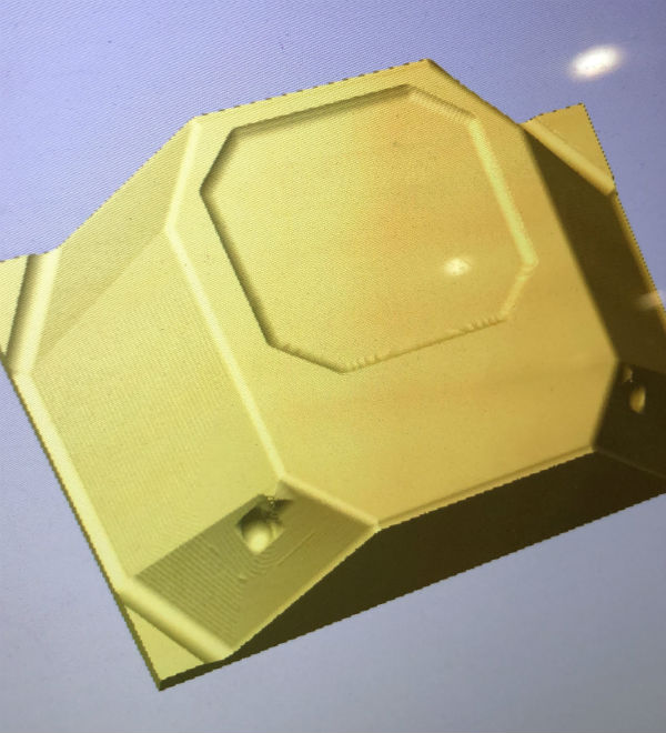
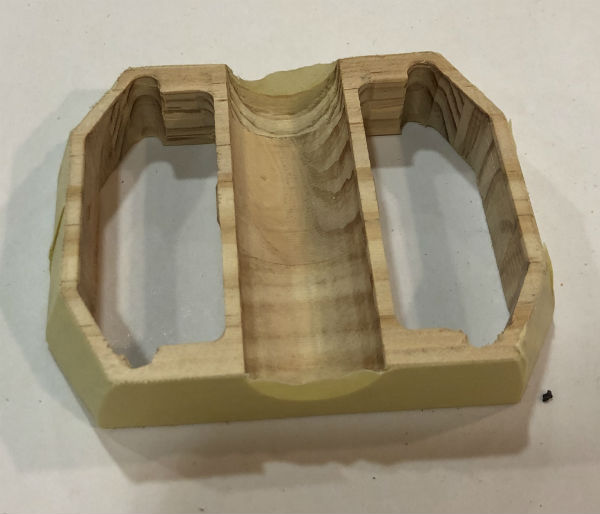
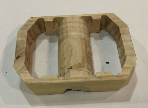
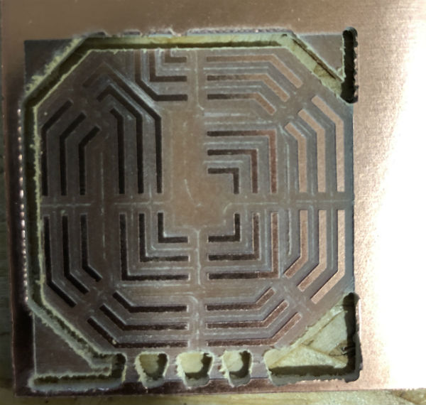
 With the pieces for the caps prepared, I introduced these measurements in the Vcarve and I was introducing the stl of each lid, extracted from catia. each cap requires 4 processes, roughing and finishing on one side and roughing and finishing on the other. In total there have been 12 processes.
To keep the piece in the right place and store the zeros for both sides, screw a piece of conglomerate to the milling table and cut a square the size of the piece of wood (with a negative adjustment of 0.3 mm. not to move the piece), to later introduce it inside and use those zeros. The only zero to modify all the time is the z since it depends on the thickness of the material.The toolpaths and tools that I have used correspond to the same ones used in the assignment of wildcard week
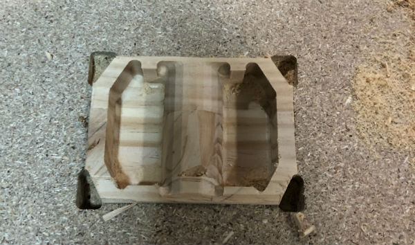
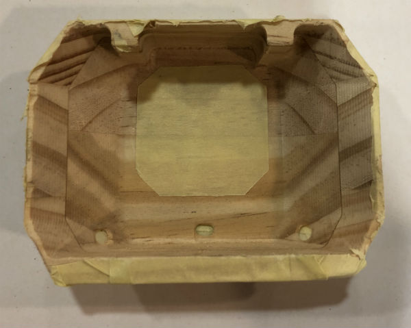
In the images that I show below you can see the process:
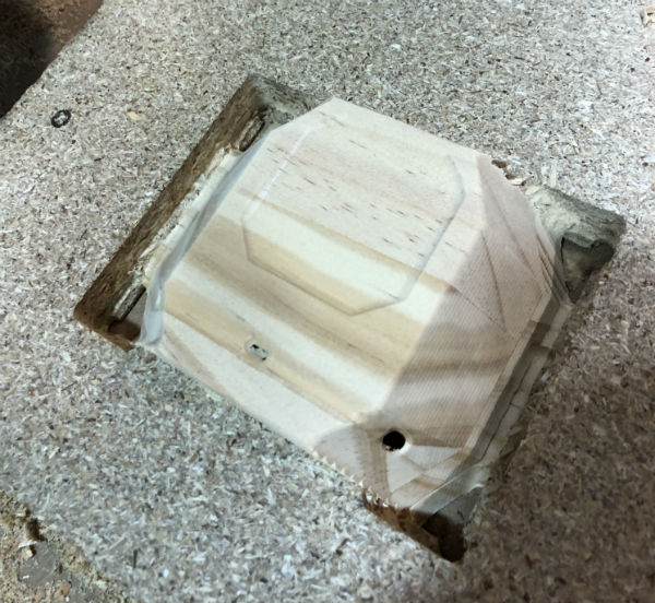
 To ensure that the light did not pass through the whole piece, since it has a wall of 1.5 mm and only passes through the milled part to 0.5 mm, I had to paint the inside of all the black caps, for this I have masked the pieces and I applied a black spray on the inside of these.
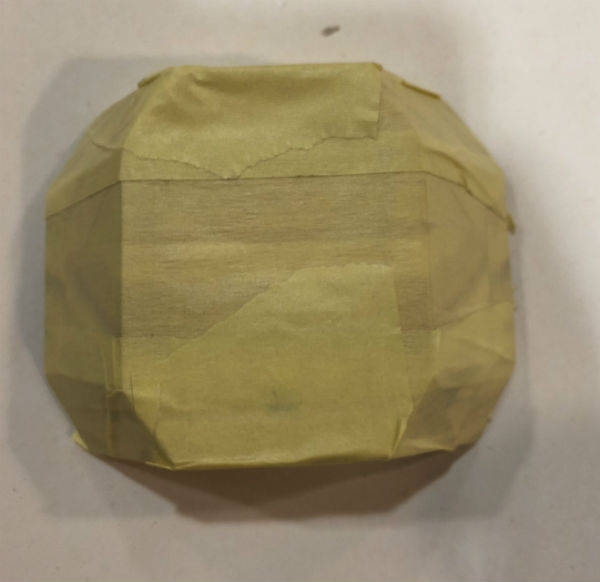
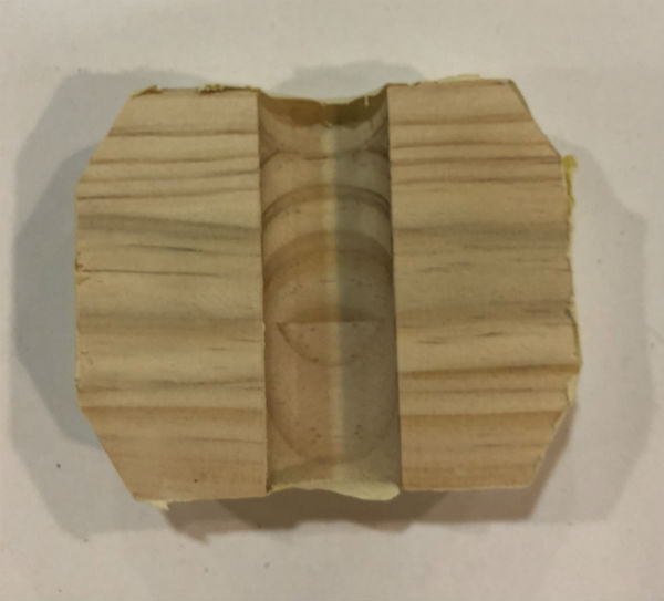
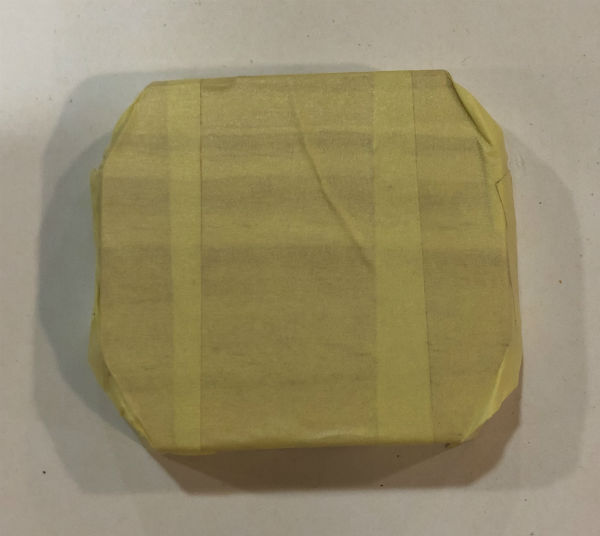 At the end of the entire process of manufacturing and assembly of the project, use a drill to make the housing of the M3 screws.
Electronics production
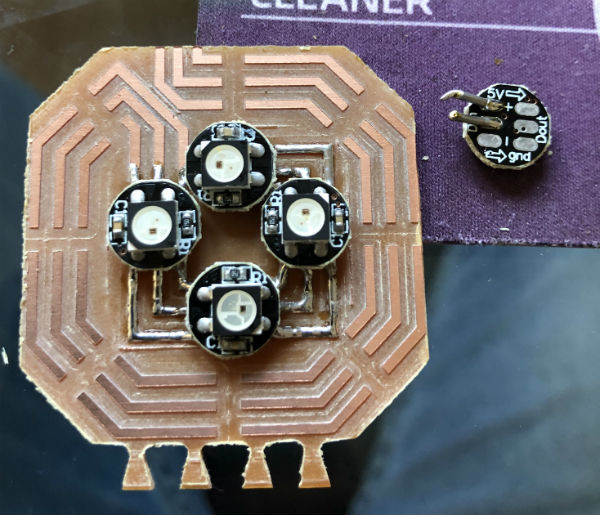
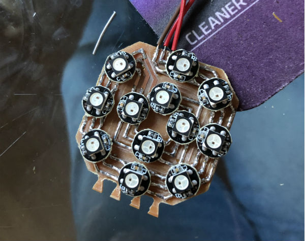
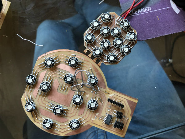
This part of the project is the one that has given me the most problems, since the assignment of output, I focused on creating an array of led neopixel with which to create the necessary lumenic signals for my piece. As you can see in the end I got it, but this array was very large and I decided to improve it and make it smaller.
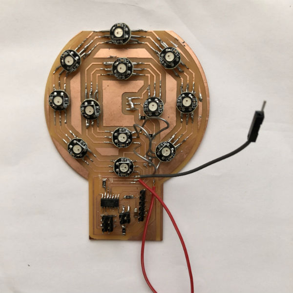
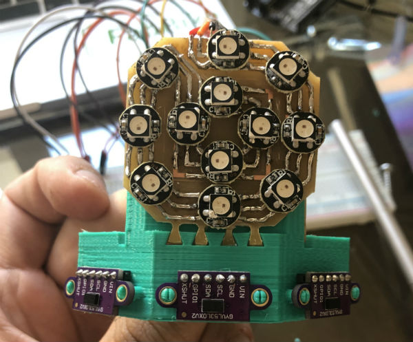
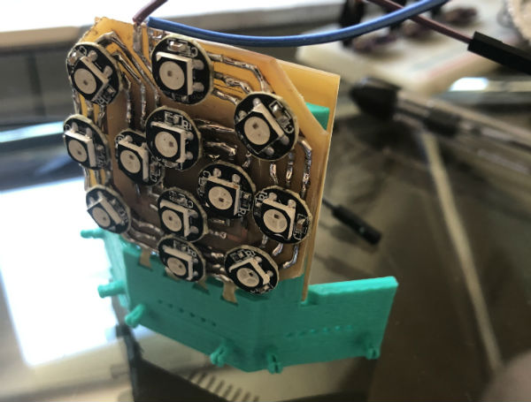
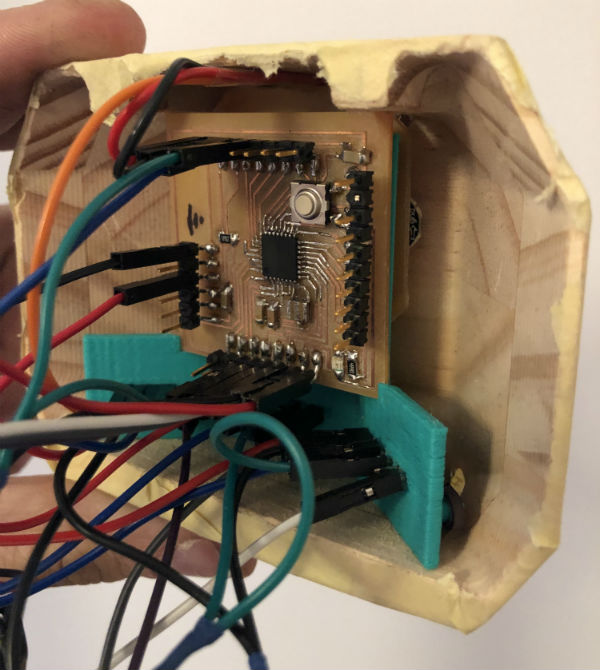
 Then I incorporated it into the piece in which I was going to join all the electronic elements and in which I had already placed the three laser sensors VL53L0X.
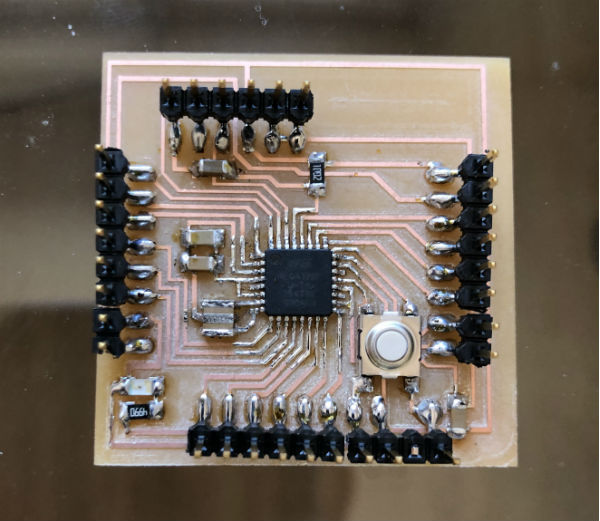
 To connect the whole set and communicate them to each other so that they work through the i2c communication channel, I have resorted to using an Atmega328p.
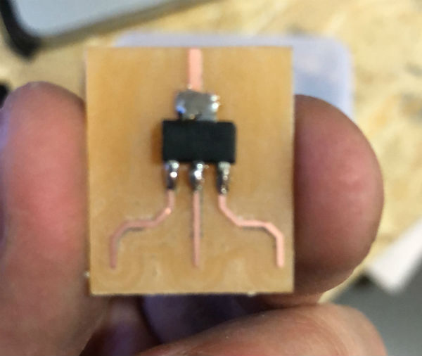
 Once connected everything I realized that I had not incorporated the voltage regulator for the 9v battery that I wanted to use, whose voltage had to convert to 5v. for this I have manufactured an auxiliary plate with the regulator, to which I have soldered the power cables and I have covered with thermoretractile tape.
 I have connected everything, I have launched one of the test programs that I explain below in the programming part and finally the project works.

Programming
To program the different elements I have been testing the boards in parts and making progress little by little in each part. The progress of these parts can be seen in the assignment of output.
In this part I will show the different tests that I have been doing on laser sensors together with the neopixel LED array already integrated.
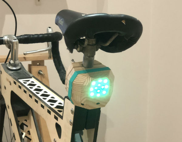
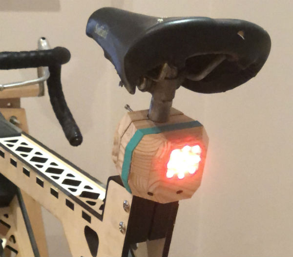
In the next video we can see how one of the three sensors modifies a comercial LED array as a function of distance and this array goes through three different phases of color, green, orange and red.
Final project images