16. Interface and Application Programming
- Group assignment http://fabacademy.org/2019/labs/lakazlab/assignments/week16/
- comparing as many tool options as possible.
- Individual assignment
Objectives
- [x] Interpret and implement design and programming protocols to create a Graphic User Interface (GUI).
- [x] Described your process using words/images/screenshots
- [x] Explained the the GUI that you made and how you did it
- [x] Outlined problems and how you fixed them
- [x] Included original code (or a screenshot of the app code if that’s not possible)
User interface for the revolver nozzle holder
This week i will build a UI for both configuration and Jogging and control of the revolver nozzle holder i am building for final project.
As said before i will NOT focus on building a full end-to-end Pick and Place solution but rather hack into the existing OpenPNP framework.
When building a pluggable piece of infrastructure it is important to have the software for it just as pluggable as you intend the hardware to be. So i will build a widget/plugin on HTML5/Javascript standards that could open serial communication with the Revolver Nozzle holder and configure and control all possible aspects of this system.
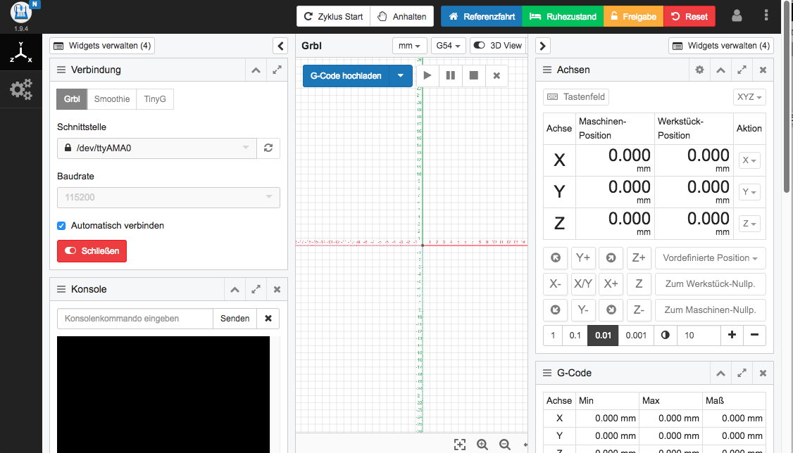
Personally i am also very charmed by the CNCJS fully JavaScript CNC UI that i successfully tweaked for the Digital Artist our group built in week 15 and 17. So for simplicity i will now just integrate it with CNCJS again but the ultimate goal is to integrate it into OpenPNP directly.
OpenPNP is built in Java with SWING framework and there is JavaScript and Python scripting integration. This integration is NOT perse by means of adding Widgets but more to access global variables (like machine settings and position).
The hook for the Revolver Nozzle Holder would be here:
NozzleTip.BeforeLoad
Called before a new NozzleTip is loaded.
Variables:
| Name | Type | Description |
| head | org.openpnp.spi.Head | The Head the NozzleTip belongs to. |
| nozzle | org.openpnp.spi.Nozzle | The Nozzle the new NozzleTip was loaded in. |
| nozzleTip | org.openpnp.spi.NozzleTip | The NozzleTip that will be loaded. |
There are plenty interfacing options but not enough to completely skin-off the OpenPnP with a full JavaScript UI (if that is even desirable).
So lets look at the baseline UI’s first:
CNC.JS
OpenPNP UI
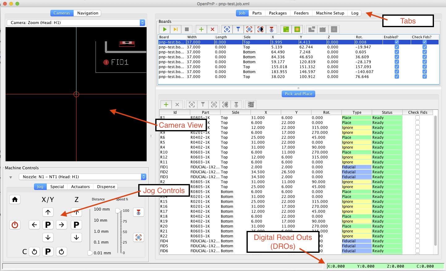
The elements that matter for the GUI are
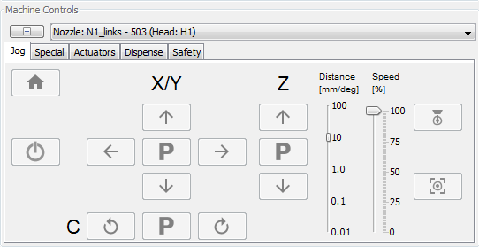
OpenPNP JOG Pendant/UI
With the axis for motion described here
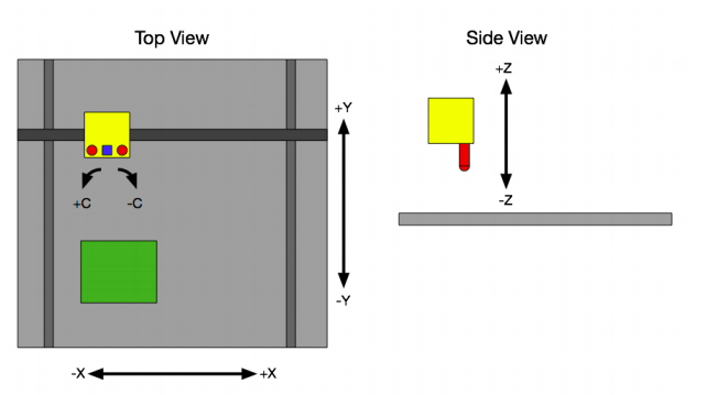
For my project i want to create the OpenPnP compatible JOG controller that also handles the hooked head/nozzle/tip displacement settings. After that a hack must be applied to OpenPNP faking the head displacements in “degrees revolver rotation” instead of XYZ displacement as it is now done.
I will probably have to contact the creators to provide the hooks or a post feature request.
Required functionalities for RotoPick
Functionalities required for the system to operate:
- Serial communication (over Virtual COM port)
- Jog/Calibrate and HOME functionality
- Control Rotate Revolver
- Control Rotate Nozzles
- Punch down
- Control XYZ
- GCode interface / serial over Web
- Pick and Place user interface
Optional is to remote control the XYZ controller over VirtualCOM (Arduino Mega/Ramps14)
Pick and Place Data interface
Pick & Place files are used to relay the component position and orientation on the board to the system.
Eagle CAD
- In EAGLE, run mountsmd.ulp, which is included in the EAGLE distribution.
- In OpenPnP, go to the menu at File -> Import Board -> EAGLE mountsmd.ulp.
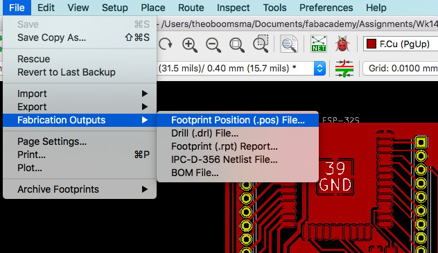
KiCAD
- File -> Fabrication Outputs -> Footprint Position
- In OpenPnP, go to the menu at File -> Import Board -> KiCAD .pos.
Typically formatted like this
Module positions - created on 2019 June 25, Tuesday 15:55:26
Printed by Pcbnew version kicad (5.0.2-5-10.14)
Unit = mm, Angle = deg.
Side : top
| # Ref | Val | Package | PosX | PosY | Rot | Rot Side |
| C1 | 10u | fab-C1206 | 8.29 | 17.99 | 270 | top |
| C2 | 1u | fab-C1206 | 25.79 | 18.49 | 270 | top |
| M2 | MICRO-USB | fab-USB_MINIB | 20.79 | 3.99 | 90 | top |
| R3 | 1k | fab-R1206 | 22.29 | 11.49 | 0 | top |
Serial communication over IP (VCom)
To allow interaction with the connected serial devices (the motor controllers etc) and host a serial command monitor. This will be done via the NodeJS infrastructure as a gateway to all lined Serial Devices.
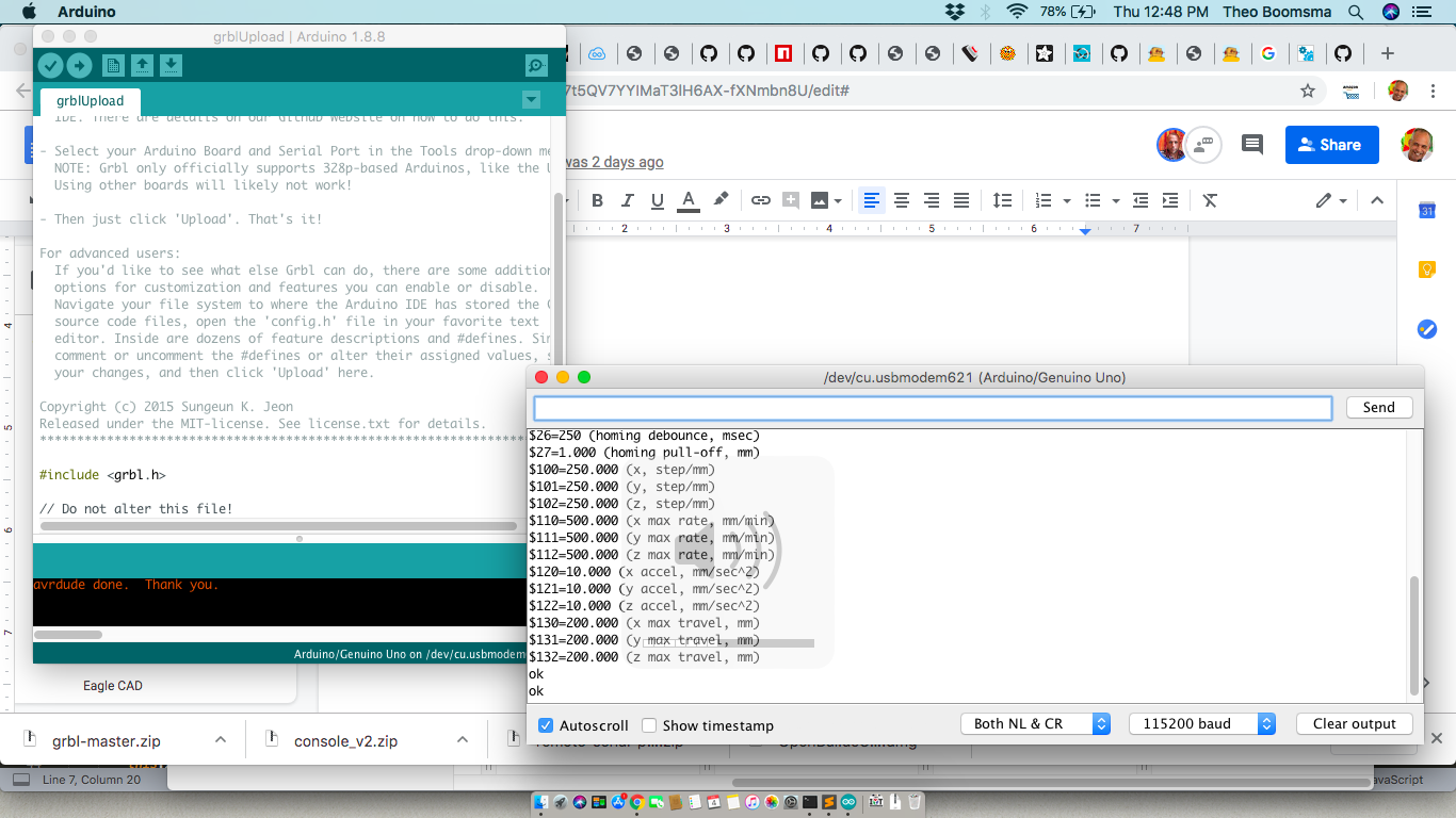
- Connecting directly with Arduino IDE / Serial Monitor
2. Connecting to local machine infrastructure
To make a remote TCP hosted Serial port local on the host i will use the [SOCAT library
](https://www.acmesystems.it/socat) as referenced in this article
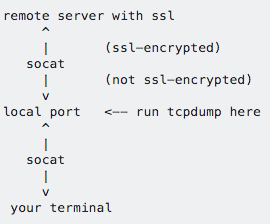
One could either connect the remote COM as local by creating a SymLink to any remotely shared Virtual Serial
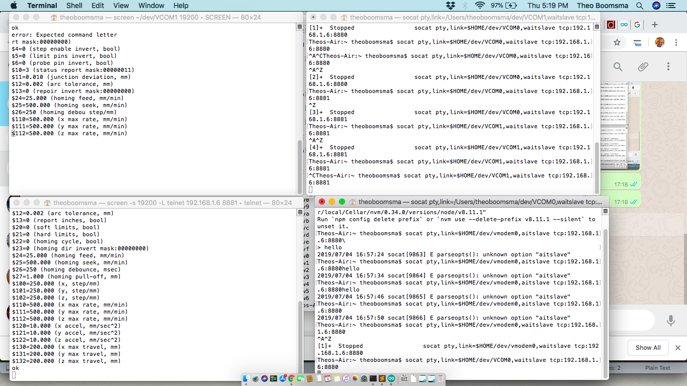
First make a receiving device folder (don’t try /dev/ folder in OSx as it is disabled even for Root users)
$ mkdir /$HOME/dev
Connect that device under “VCOM0” folder to the external Serial Device
$ socat pty,link=/dev/VCOM0,waitslave tcp:ESP32_IPADDRESS:ESP32_PORT/
(eg for COM1: socat pty,link=$HOME/dev/VCOM1,waitslave tcp:192.168.6:8881)
OR connect directly under telnet with
$ screen -s 19200 telnet 192.168.1.6 8881
Connect via HTML5 Dashboard
Last hurdle is the direct connection to VComs straight from HTML5 Dashboard
All we need is to pass such a call and receive responses and if i had enough time i would hack a tool like Remote-Serial-Port-Server/Client ](https://github.com/papnkukn/remote-serial-port-server)
and just take out the client side library (their client works only with the own server).
Setup host environment (ESP32)
The host environment will run on the ESP32 proto board i built in week 14.
I wanted to run it on LowJS, a NodeJS fork specifically slimmed down for Embedded systems like the ESP32.
Take 1: LowJS a NodeJS fork
Install the LowJS on your computer first
$npm install --unsafe-perm -g lowsync
Make your project folder and initialize with
$mkdir rotopick

$cd rotopick

$lowsync init
You will be asked for the desired device IP on the network and local folder to be synced to the device
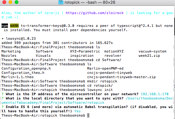
Flash the firmware to the ESP32 using the FTDI cable
$lowsync flash /dev/tty.usbserial-FT9P07SR –init
After that OTA updates are possible with just the IP address of the device
UPDATE: Unfortunately the LowJS firmware is only build for the ESP32-Wrover module and does NOT run on the Wroom-32D module so i decided to go native Arduino IDE
Take 2: Async HTTP webserver on Arduino IDE
Since i only have to host a static HTML Page(SPA) for the dashboard and all processes will run on the loading browser i will just switch to a simple HTTP server.
Doing HTML inside the C code is horrible so i will just serve up a set of file from a sub-folder on the ESP32. Inspiration came from this blog
I will use the ESPAsyncWebServer.h libraries for HTTP server, so it can be reached by clients connected to that same network.
Also we will be serving up static content from the file system thus we need to include the SPIFFS.h library. This include will make available a extern variable called SPIFFS that we can use to mount the file system and open files.
To save space all extra Javascript libraries like jquery and so, will all be externally hosted as much as possible so the client will need to have Internet access anyway. Maybe later stage i will try to minify and add locally too.
Include this code to the Week 14 code to add an extra separate HTTP server listening to port 80 (to not interfere with the VCom’s)
    #include "SPIFFS.h"
    #include "ESPAsyncWebServer.h"
    AsyncWebServer server(80);
Building the Dashboard / UI
As seen above the elements of any UI are a main screen or dashboard containing a set of widgets doing a specialized task semi-autonomously.
The widgets are often draggable and can be moved around the Dashboard by user preference.
Each widget containing active elements will be configured via a built in configuration widget.
The settings for each widget or object will be persisted across reboots or the main system.
A mockup of the build:
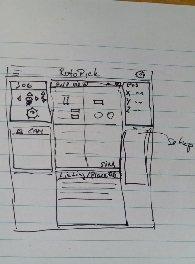
I will follow the same structure using Javascript libraries for each function.
Gridstack will provide the draggable canvas for hosting widgets
QuickSettings for the widget configurator
LowJS ESP32 NodeJS version (UPDATE: does NOT run on ESP WROOM 32D module)
Using the ESP-Serial-Bridge in C code directly in ESP32 and added a AsyncWebserver
The UI build step-by-step
Walk through the UI build here.
1.Create a widget base-line for the UI.
Build the basic drag and drop canvas (i will mimick CNCJS layout as much as possible)
As the mockup suggest we are talking about a 12x12 grid here with the middle for the main widgets and the sides for the supporting widgets. This was inspired on this article on GridStack
Dashboard.html
    <!DOCTYPE html>
    <html lang="en">
    <head>
      <title>A gridstack.js dashboard</title>
      <link rel="stylesheet" href="https://bootswatch.com/3/paper/bootstrap.css">
      <link rel="stylesheet" href="https://cdnjs.cloudflare.com/ajax/libs/gridstack.js/0.4.0/gridstack.css"/>
      <script src="https://ajax.googleapis.com/ajax/libs/jquery/3.3.1/jquery.min.js"></script>
      <script src="https://cdnjs.cloudflare.com/ajax/libs/jqueryui/1.11.0/jquery-ui.js"></script>
      <script src="https://cdnjs.cloudflare.com/ajax/libs/lodash.js/4.17.0/lodash.min.js"></script>
      <script src="https://cdnjs.cloudflare.com/ajax/libs/gridstack.js/0.4.0/gridstack.all.js"></script>
    </head>
    <body>
      <div class="container">
        <div class="row">
          <div class="col-sm-12">
            <h2>RotoPick dashboard</h2>
          </div>
          <div class="col-sm-12 well">
           ** <!-- add your gridstack.js elements/widgets here -->**
          </div>
        </div>
      </div>
    </body>
</html>
We have our widget grid baseline and we add some basic widget containers to it .. we will need for now.
The basic Widget container/placeholder looks like this
      <div class="grid-stack">
        <div class="grid-stack-item" data-gs-x="0" data-gs-y="0" data-gs-width="2" data-gs-height="2">
          <div class="grid-stack-item-content panel panel-primary">
            <div class="panel-heading">
              <h3 class="panel-title">Status</h3>
            </div>
            <div class=panel-body">
              content here
            </div>
          </div>
        </div>
We will need 2x small (3x3) for Position + CAM, 2x big (6x6) for JOG and Main and a wide/flat one (6x3) for Pick List.
Before all the widgets become draggable we should add this piece of code to the HTML file just before closing the “body” tag
    <!-- ...
        <script type="text/javascript">
            $(function () {
                 $('.grid-stack').gridstack();
            });
        </script>
    </body>
The Basic UI looks like this
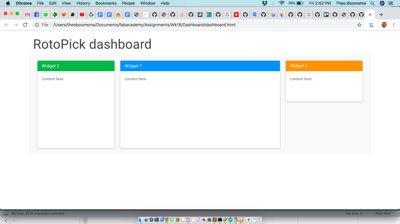
Note: All widgets are scalable live so make sure the code inside them also scales as nice as possible.
2.Lets add the basic widgets (JOG, Serial Command interface for now)
To add content and active components to the widget placeholders simply insert your looks and programming logic.

Others / To Do
3.Create the Configurator UI baseline.
The QuickSettings library works with a JSON object containing all the settings with their value. The idea is that the QuickSettings form scaffolds the JSON configurator object of the “to be configured widget. This means we just have to put in the default widgetx_config.json object for the configurator to pick up and scaffold the elements of the UI.
4.Other basic functionalities (out of scope for now)
Platform tooling like authentication, data persistence for configurations and the system-wide parameters.
5.Data Persistence / storage (out of scope for now)
I will use a helper class called that will connect all active components to its data-element in the big configuration. Deep-linking binds any active element directly to a subkey of a big JSON object. This object can be persisted in local storage or on the server-side.
We will persist across reboots/logins:
- Application level settings (selected widgets)
- User selections/customizations
- Widget settings (in widget settings)
The results
Video from the Web User Interface for the RotoPick infrastructure setup
Video 2 after i found out how to reset the “end-stop” alarm status we got MOTION!
Files & Downloads
Files included:
- ESP32 Virtual Serial firmware
- Dashboard code
References
SoCat server/client by example