8. Computer-controlled machining
- Group assignment http://fabacademy.org/2019/labs/lakazlab/assignments/week08/
- Test runout, alignment, speeds, feeds, and toolpaths for your machine
- Individual project
- Make (design+mill+assemble) something big. \
Objectives
- [x] Explained how you made your files for machining (2D or 3D)
- [x] Shown how you made something BIG (setting up the machine, using fixings, testing joints, adjusting feeds and speeds, depth of cut etc)
- [x] Described problems and how you fixed them
-
[x] Included your design files and ‘hero shot’ photos of final object
-
[x] Screenshots and description of the process of designing (explain the function of t-bones).
- [x] Describe the process of exporting your design and using Vcarve or Fusion360 to create the G-code.
- [x] Mention the parameters you used for cutting your design: end mill ∗ number of flutes ∗ length of flutes ∗ diameter ∗ cut depth ∗ passes ∗ adding tabs
- [x] Photos of the cutting and assembling process.
- [x] Describe any errors or problems with the process and how you fixed them
- [x] Photos of your design
- [x] Include all the les you created for download
Individual assignment: Make something BIG
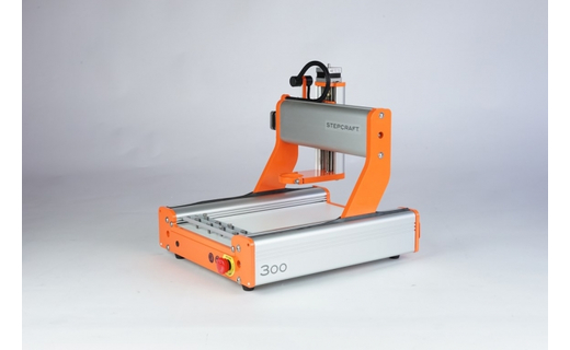
My idea was to make BIG impact rather than BIG physical object. Since we’ve started the FabAcademy our group of 8 has been milling many PCB’s on the StepCraft 300 machine and since the machine shares the same space we work and it make a lot of noise i decided to build it an enclosure.
 \
\
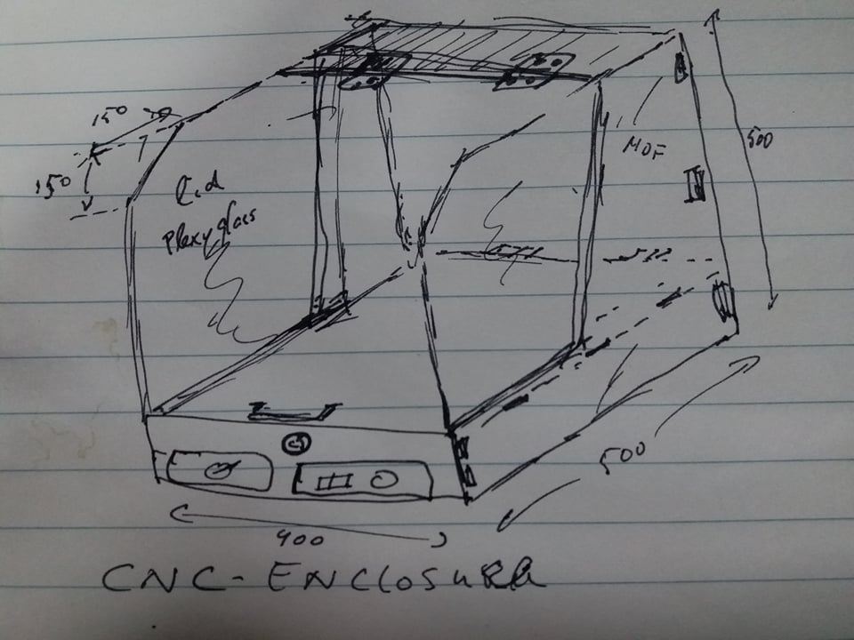
I will implement a mix of press-fit housing with a plexiglass cover and some hinges. Later i will include lid-open safety lock and include vacuum dust collector system.
This enclosure will serve as a proof of concept design for the bigger StepCraft 840 we have also.
Making panels fit without the need of screws we tested some press-fit scenarios in the group assignment. Nevertheless i decided to also add pockets for screwing things together as the mill will be subjected to heavy use and continuous vibration.
Design steps:
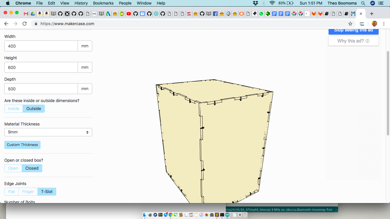
- It all started with a fully containing box as baseline (courtesy of MakerCase) \
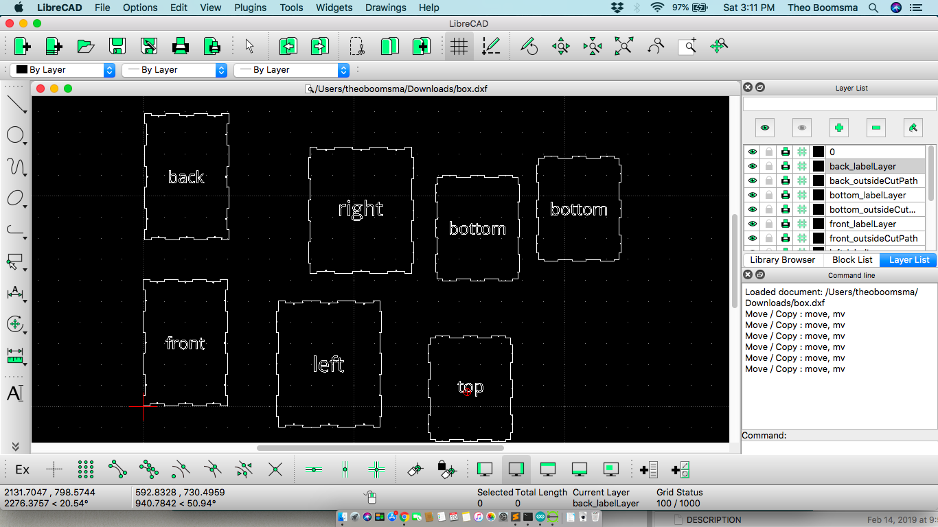
- Imported base box into LibreCAD and added the extra bottom layer i wanted for all the control boxes of the stepcraft. Also keeping cable pass through channels open. \
 \
\
-
Cutting panels to facilitate the Plexiglass cover lid, the cable passes, access to the control modules. I made heavy use of the \
-> Tools / Modify / Move - to drag/arrange panels and elements \ -> Tools / Modify / Trim - to cut sections based on intersecting guidelines \ -> Parallel Line - to create guides for cut out boxes \ -> Circle - Center/Radius - to place the Bones for fitting pockets \ -> Tools / Fillet - for rounding corners of opening
-
Creating and positioning the bones is a tedious task since you have to match the exactly with incoming panel. For the middle layer (machine floor layer) i had to manually align them with the bottom panel as template for positioning on sides and front layer. \
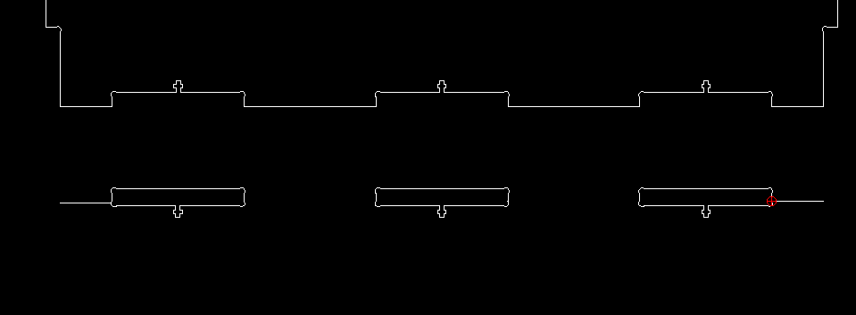
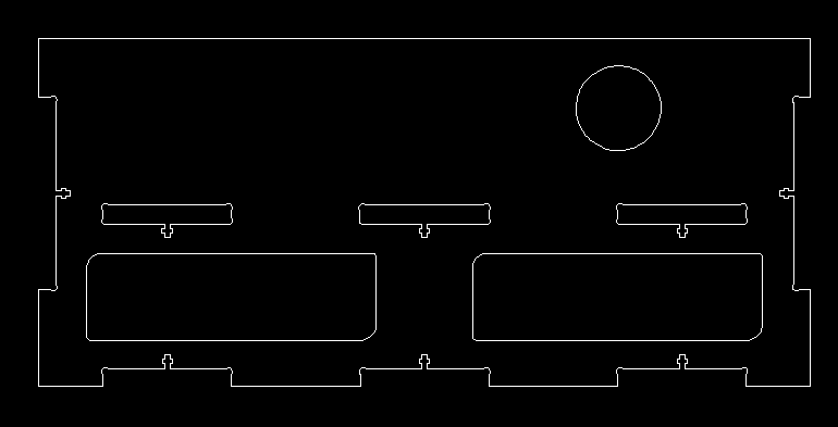
- Once i got the bone templates my design strategy was very rudimentary. I just started working from the base-plate up by measuring component heights adding a bit of space above it, add another floor and measuring up to the position of the Emergency Stop button and so forth. For example the front panel hosts the openings for the controller boxes for Spindle and tool changer, the emergency button and the pockets with bones for the 2nd layer. See image \
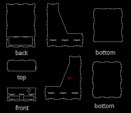
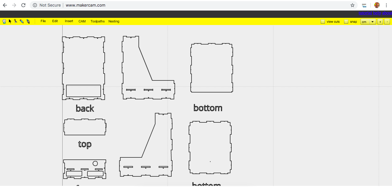
- Final resulting panels for the enclosure
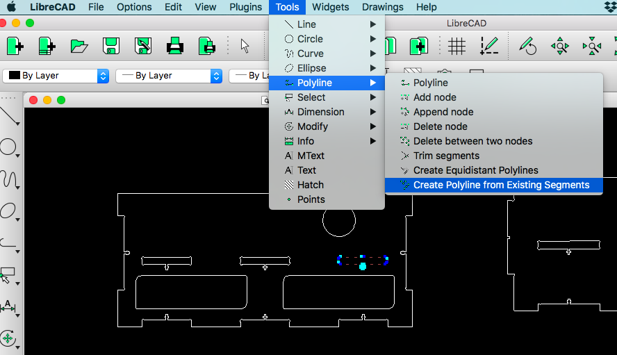
- For machining i exported the design to SVG for MakerCAM.com. Important before exporting to MakerCAM SVG is to generate polylines for each of the elements. All pocket cut items should be separated from the outside cut items! If not MakerCAM will NOT recognize them as CNC-able items. \
Open in MakerCAM \
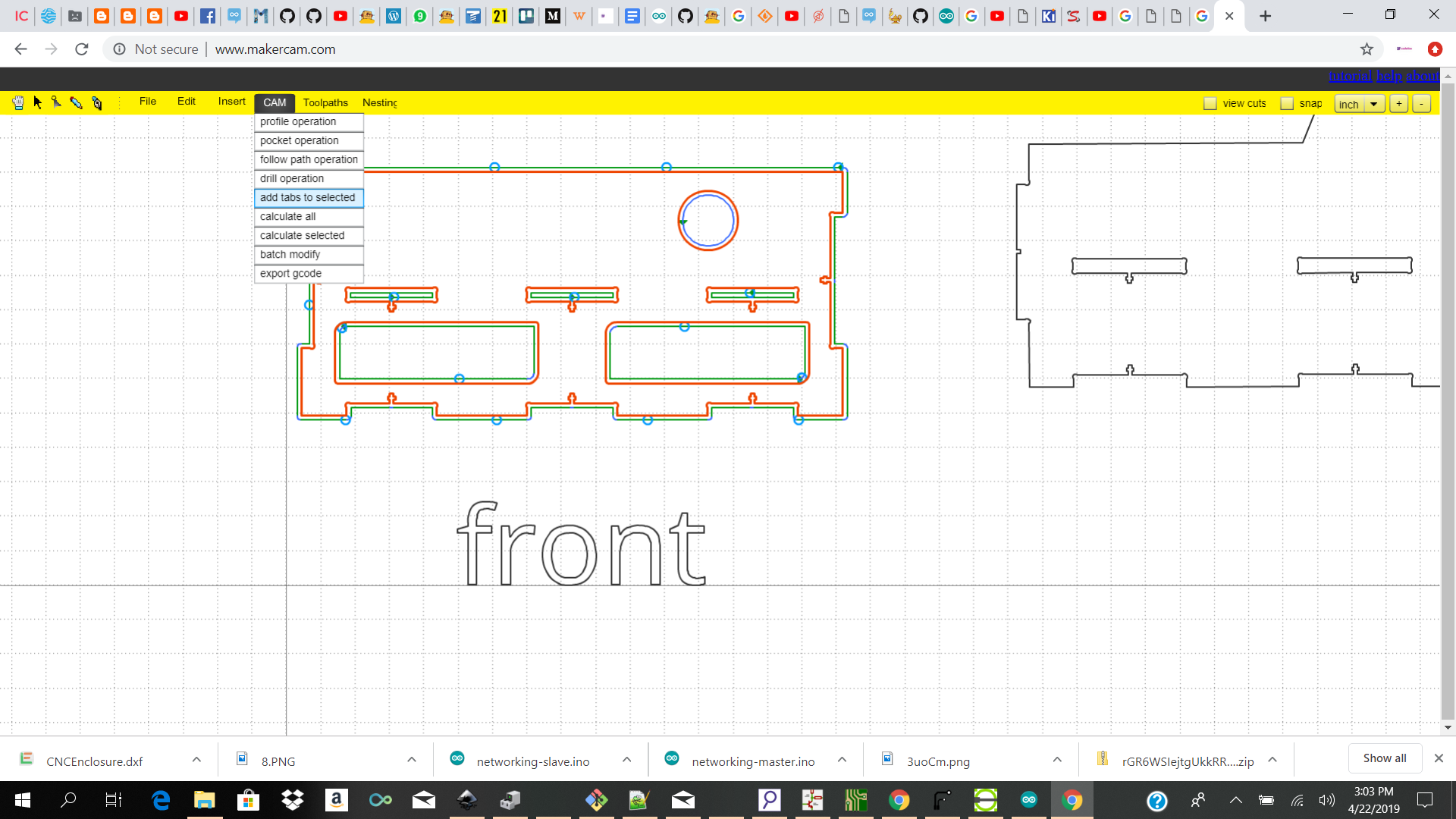
Select your items (all those you want to combine per sheet) >>CAM>>Profile and select options first for pocket cuts and then outside cuts \
After this we select >>CAM >> Calculate it takes a while to calculate tool paths based on your selected machining settings.

Don’t forget to add the tabs for holding together the pieces during milling (unless you want to keep holding down your pieces)
Now we select >>CAM>>Export GCode a popup allows us to select the Profiles we want to export (combine) in the gcode.
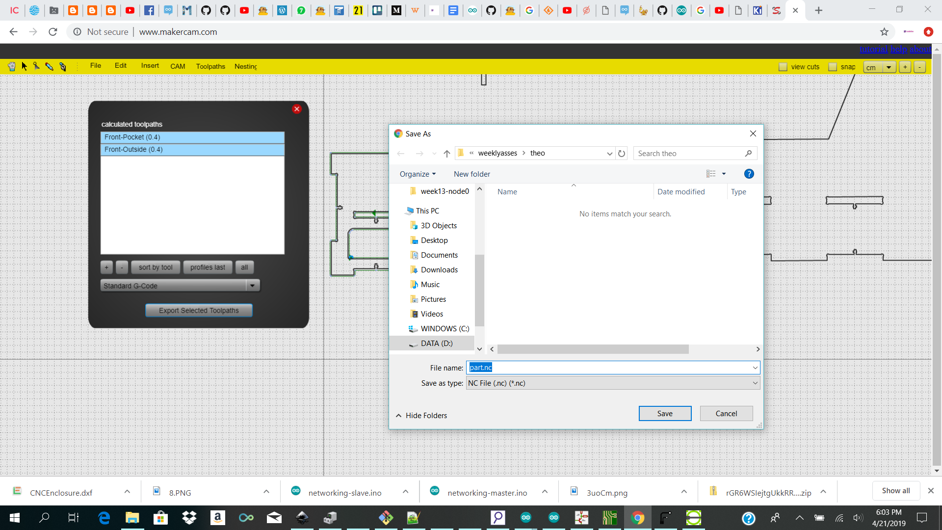
NOTE to select the Inner cuts before the outside cuts. The app allows you to change the order.
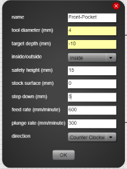
 Milling the panels


For milling these panels i used the Stepcraft D-840 2, a small/medium size CNC with the UCCNC software.


The parameters:
| Param | Value |
| Tool diameter | 4 mm |
| Target depth | -9 mm |
| Type cut | Inner / outer (same settings) |
| Safety height / flight height | 15 mm |
| Step down | 4.5 mm (router bit) |
| Feed rate | 600 mm/min |
| Plunge rate | 400 mm/min |
| Spindle RPM | 10000 rpm |
| CNC | Stepcraft 2 D840 |
| Spindle | 1000 Watt / RPM Variable to 20k |
Steps:
- Pre-cutting the MDF panels to size.
Since the Stepcraft workpiece size is 840x600mm max it is really important to do a good planning of panels to fit on each of the pre-cut pieces as reduce cut losses. This is ofcourse less of an issue with big size CNC’swhere u work from a full sheet. \
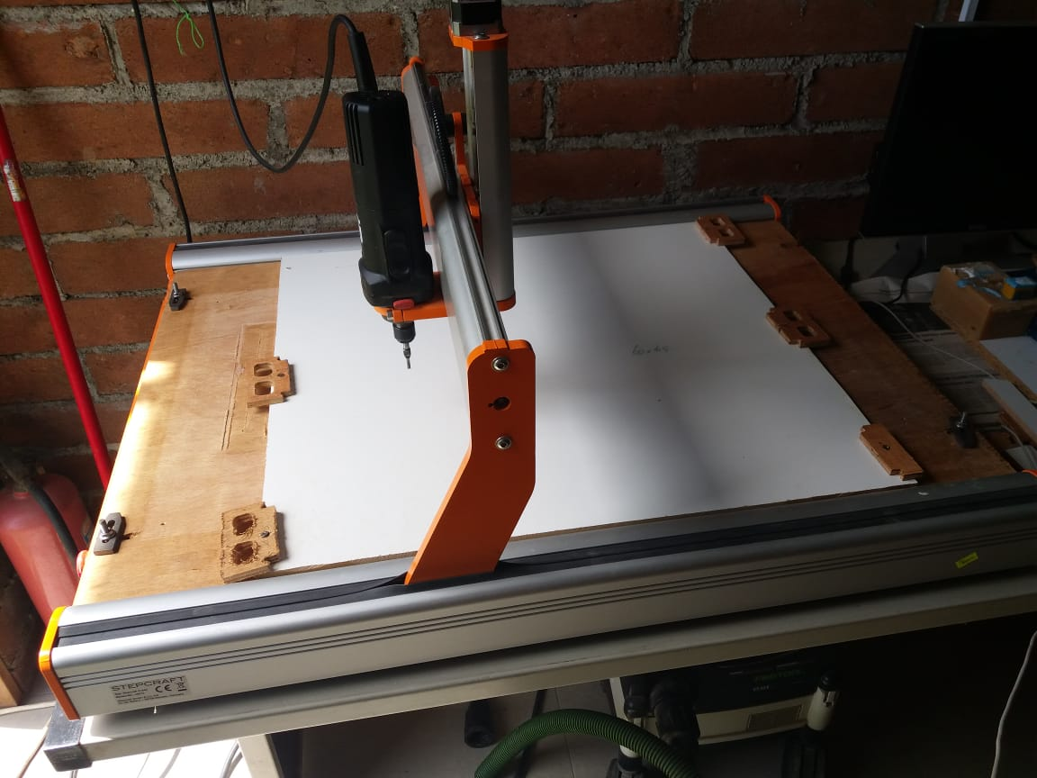
- Attaching worksheet
Attach worksheet to CNC is done with some helper blocks that are screwed through the panel in the corner and connect all the way into the sacrificial layer (9mm plywood) \
- UCCNC - GCode processor software
Load your Gcode / nc file into UCCNC and review the toolpath.
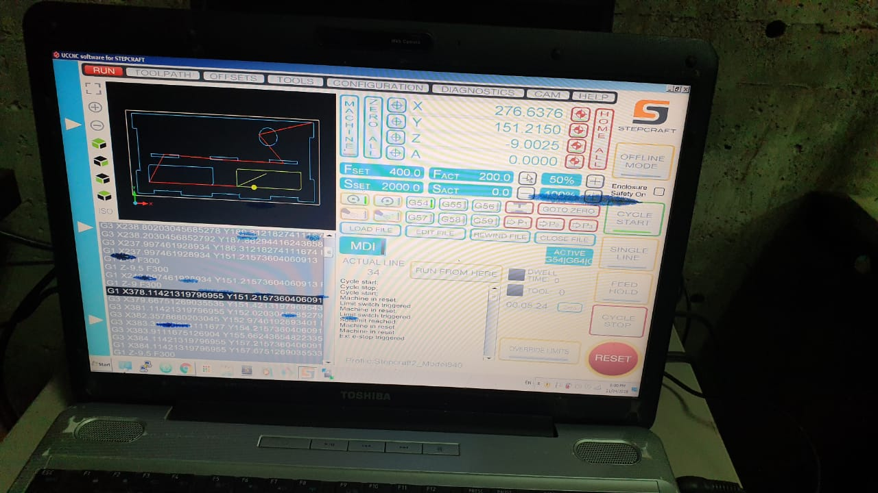
UCCNC allows you to jog and hover over the extremes of your design so you could review position of your XY start position before milling.
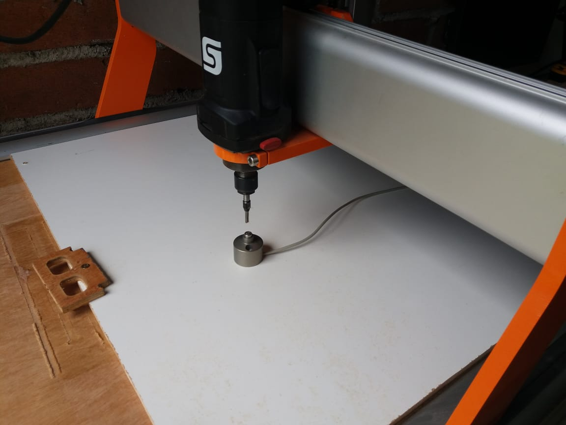
- Z-zero detection
After this its about detecting the workpiece zero position and checking the design to fit on the workpiece. We used a tool height sensor and the functionality in UCCNC te perfectly determine the Z zero. \
- Start milling / Start Cycle
Keep your hand near the reset button in case something goes wrong. It often does when you just starting with a new machine! UCCNC allows you also to slow the feedrate if you think you mill sounds “unhappy” or is missing steps. We were initially running too high feedrates causing the CNC to lose steps when making turns or in corners. Finally i got real nice results with a lower feedrate with deeper cut with a router-bit. See my results
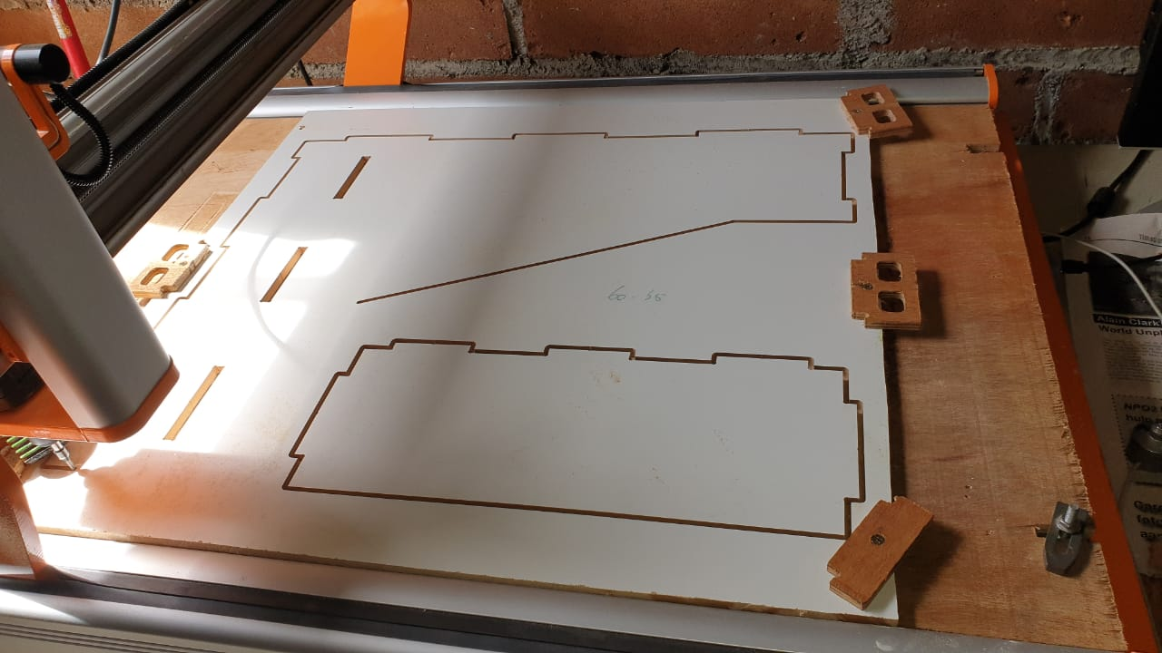
Example of tight fitting of panels on the sheet.
- Note/mark down your XY current zero position and place each following panel approximately in the same position (or use some sort of spacer to easily find it on the next sheet placement). After this it is not needed to rescan the Z-zero, just see if your milling paths fall within the limits of the underlying sheet and mill again.
Assembly
Now the fun part … fitting it all together!
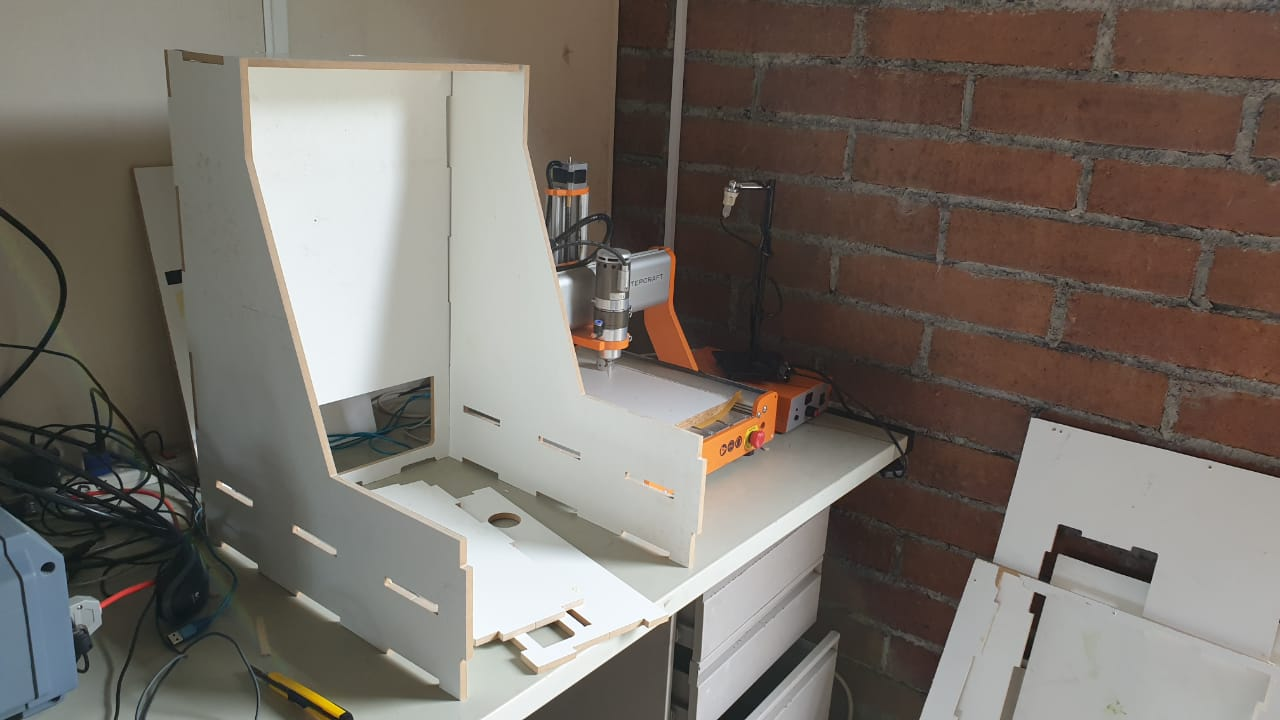
Enclosure to be next to future tenant!
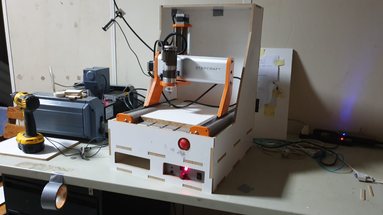
Fits perfect!
Only have to source some plexiglass, hinges and some gas springs to make the lid open like a Lamborghini door ;)
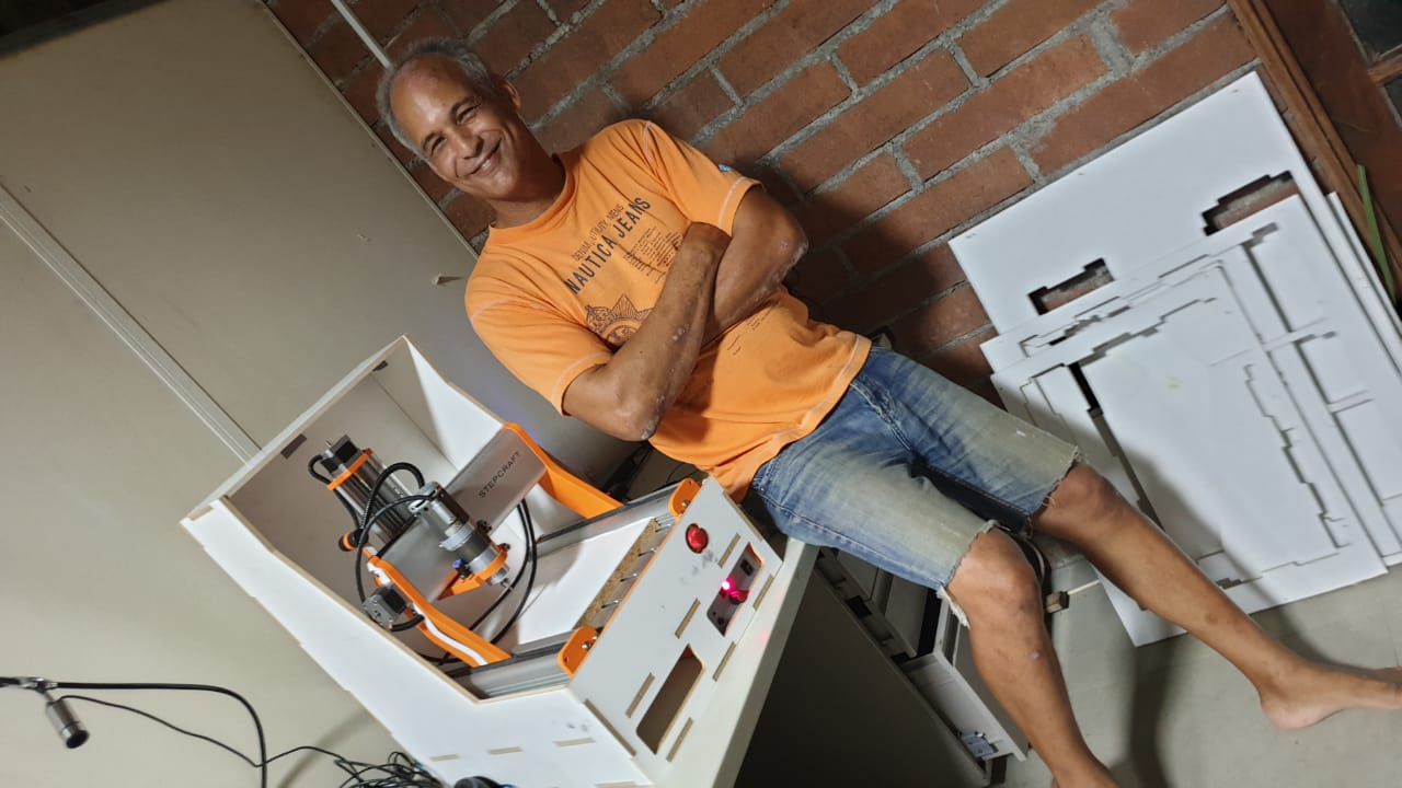
Me soo happy .. by far the hardest most stressful assignment of FabAcademy DONE!
Files
Week 8 files & downloads containing MakerCase, LibreCAD, MakerCAM dxf, svg & NC files