11. Input devices
Group assignment http://fabacademy.org/2019/labs/lakazlab/assignments/week11/ Measure the analog levels and digital signals in an input device
Individual assignment Measure something: add a sensor to a microcontroller board that you have designed and read it.
Objectives
- [x] Described your design and fabrication process using words/images/screenshots or linked to previous examples.
- [x] Explained the programming process/es you used and how the microcontroller datasheet helped you.**
- [x] Explained problems and how you fixed them
- [x] Included original design files and code
- [x] Add link to the group assignment.
- [x] Screenshots and description of the process of creating your board.
- [x] Screenshots of soldering and debugging process.
- [x] Describe the programming of the board
- [x] Photos or videos of your board working.
- [x] Describe any errors or problems with the process and how you xed them.
- [x] Include all the les you created for download.
Designing and End-stopper / Proximity sensor
This week we design and implement a combined End-Stopper sensor based around the Atmel ATtiny45. It is a very small form-factor Microcontroller and looking ahead at output week we will try to implement a bi-polar stepper controller around it and integrate this end-stopper. The only challenge here is to use the limited amount of I/O pins as efficiently as possible.
The sensor we will implement on a single I/O channel using the combination of end-stopper (all-or-nothing switch).
The idea is that this end-stop sensor physically blocks the stepper motor to move further once the end-stop has been triggered.
To keep pins available for the 4 stepper outputs the only pin left to hijack for the end-stop was the “step-pin” by means of disabling the step functionality with a PNP transistor when end-stop is reached (hardware disable).
We have electronically NO step functionality left to continue in any direction as all step pulses are ignored from there on, but that’s the whole idea of course.
But then the system is stuck and we cannot move backwards either, now that’s a problem!
This we will solve in the firmware by implementing a “soft end-stop” just one step before the physical end-stop.
To go there stepper will be firmware triggered to jog slowly in reverse direction until the end-stop disable status has been resolved.
Now the “soft end-stop” will NOT accept any new steps in that same direction beyond the just determined point (software disable).
Adding a distance sensor to this will allow us also to slow the motion down before reaching physical end-stop while calibrating itself real-time with the physical end-stopper. We will implement lidar distance sensing for the final project.
Designing the board
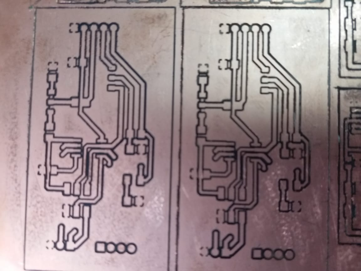
In designing PCB i will implement more Planes and thicker traces to limit as much as possible trace milling and also allowing me to make quick fixes additions easily to the board without re-milling the whole board.
Reason be that our lab currently also ran out of PCB end-mills so what we use gives us very rough traces and challenging production strategy.
Schematic of mother-board made in KiCAD
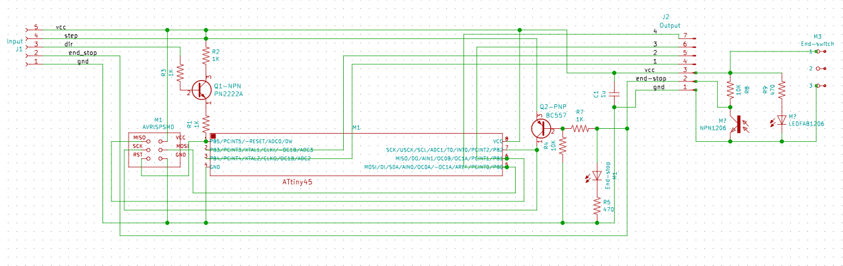
Looking ahead we try to save as many I/O pins as possible for next week. Here an idea of the full intent.
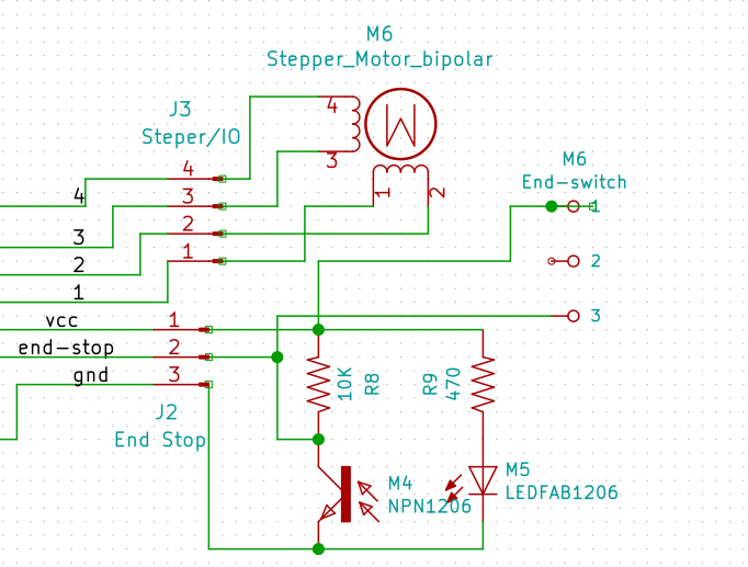
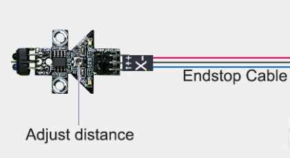
The actual sensor will be connected via the 3-pin header to a daugher-board hosting the end-stop switch and the infrared sensor.
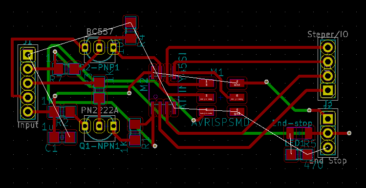
The board layout
The sensors
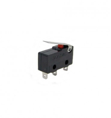
- Physical end-stop switch
- Optical end-stop/distance sensor (will be added in Final Project)
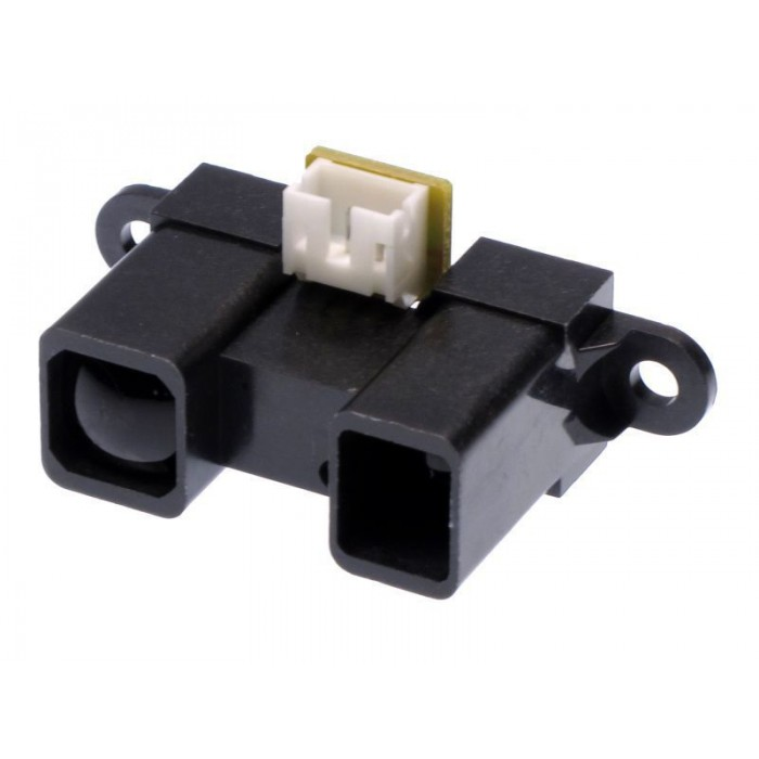
Something similar was build bi PiBot. This is essentially an ATtiny45 with some tuning logic within. My system will do the same but then detect the distance analog (which has to be calibrated in a way) and finally hit a full “ON” state when the end-stop is reached.
Milling & Soldering
For CAM i used the MODS system to generate my NC files based on exported gerber files from KiCAD. Import gerber files into FlatCAM and set the milling parameters as usual
| Flatcam | Traces |
| Tool diameter | 0.4 mm |
| Cut Z | 0.1 mm |
| Feed Rate XY | 0.3 mm/s |
| Plunge Rate | 0.5 mm/s |
| Spindle speed | 10000 rpm |
Header headers … sigh
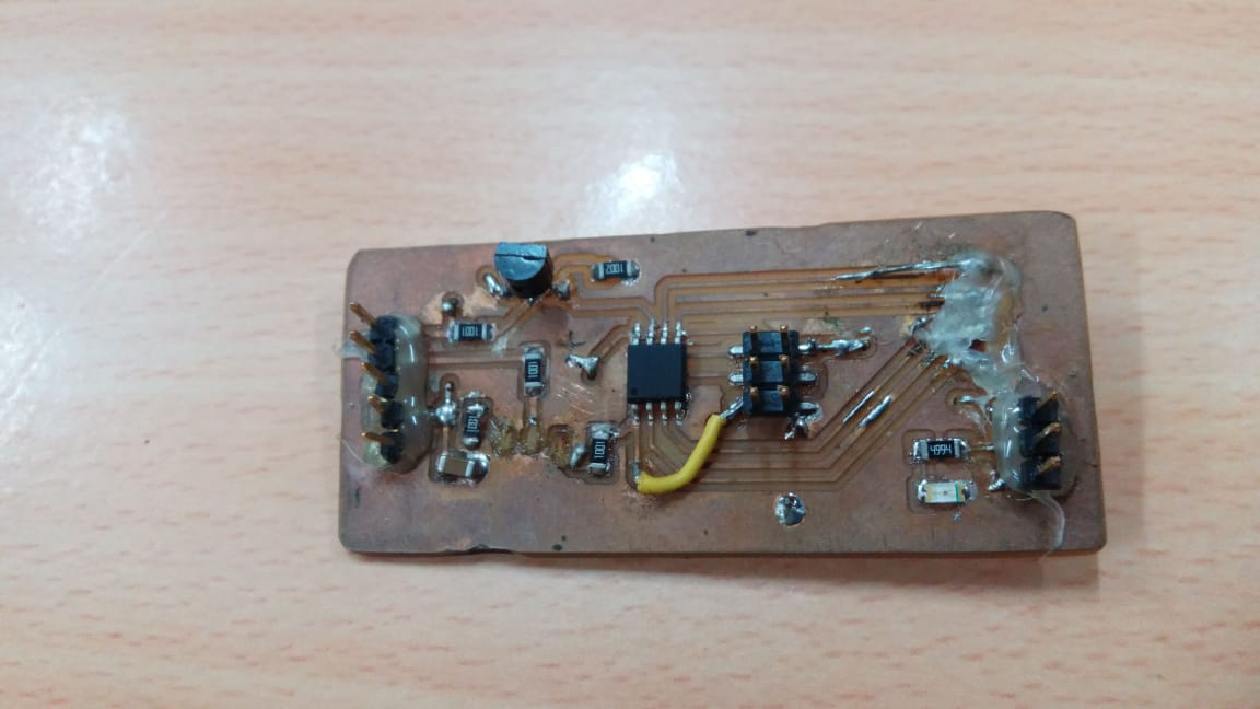
First take on it … those headers keep coming loose or worse pulling out the traces so had to hot glue them to the board with some hot glue. (making it impossible to electronically make changes also.
Long story short, i milled 2 new boards already for the coming output week too since we will be doing almost the same base board design.
I reduced the amount of Via’s because we were bridging them with little wires which was a tedious job to do. We also included 4 connectors for next week’s stepper motor control.
Heat gun soldering
I tried solder paste and heat gun soldering before but only now i see the true value of this technique as the components get too small for my eye sight for normal soldering. Looking forward to Networking week where i’m planning to use an ESP32 there that is merely impossible to solder with normal soldering iron.

I must say i LOVE the simplicity and quality of the outcome.
Programming the board
The full code of the board will be explained in week 12 because of the integration.
From the Datasheet
From the Datasheet i found the “soft-I/O option for the reset pin and also the INterrupt pins and how to program them. The STEP action is detected by connecting to the Interrupt event.
To detect the “soft end-stop status” it boils down to the Step pin detecting a sustained HIGH status telling it that the last step taken triggered the end-stopper. There will be no more steps received after this (>500ms) so it will trigger an inverse motion for a single step and set the soft-limit for that direction to on.
Code block
volatile byte curStep = 0;
byte coils[] = {0, 1, 3 ,4};

/*  ATTINY45 PINOUT  */
#define stepPin 0       //pin7 - PORTB 2 (interrupt 0)              --Used as Interrupt (so 0)
#define dirPin 0        //pin1 - PORTB 5 (analog 0) - Reset pin    --
/*
 *    The threshold that identifies if a signal is high or low. It is inside [0, 1023].
 *    For Attiny 45 this has to be the reset pin connected to a Transistor and resistors. It has to read the "low"
 *      but not Reset your microcontroller...
 */
#define highThreshold  829
#define endStopTimer 500
/*
 *    Stepper motor coil states.
 *      States with more than one HIGHs are halfsteps
 *    Dead state is the state that no current is sent to the motor.
 */
byte steps[8] ={
  0b00100001,
  0b00100011,
  0b00100010,
  0b00101010,
  0b00101000,
  0b00111000,
  0b00110000,
  0b00110001,
};
byte dead = 0b00100000;

void setup() {
  DDRB = 0b00011011;
/*  Triggers the count() function whenever a step signal is received  */
/* TB: Detect CHANGE instead and use RISING state to step and FALLING for reset timer counter */
//  attachInterrupt(0, count, RISING);
  attachInterrupt(0, count, CHANGE);
}

void loop() {
}

void count(){
    // counts RISING & RESETS Timer on FALLING
    if(PB2 > 0) {
        //serial_write_str("rising edge\n");
        // start counter & reset Soft-Limit state
        // Take the step(s)
        if (analogRead(dirPin) > highThreshold){
            // If step receiver and treshold above value step backwards in sequence
            PORTB = steps[--curStep % 8];
        }
        else{
            // If step receiver and treshold below value step forward in sequence
            PORTB = steps[++curStep % 8];
        }
    }
    else{
        //serial_write_str("falling edge\n");
        // If counter > 500ms Set the Soft-limit state
    }
  }
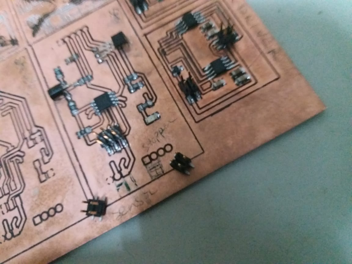
The completed mainboard with end-stopper
I combined the setup of week 11 with that of week 12 because of their integration by design.
The end-stopper disables the motion of the stepper electronically regardless of any next steps in same direction. The end-stop detection is also available on header the input side so the step dir controller will also get signal from end-stop sensor
Here the video of the functioning system of end-stopper and stepper controller. The Arduino is used to trigger the step-dir controller in a left/right sweep. Whenever the end-stopper is triggered the stepper cannot move further into that direction.
Files & Downloads
Containing: * Board design files * Code for the ATTiny45 step-dir controller + Soft Limit * Code for Arduino Step Dir control code
References
http://www.pibot.com/pibot-optical-reflection-endstop-rev143.html