4. Computer controlled cutting
Group assignment http://fabacademy.org/2019/labs/lakazlab/assignments/week04/
- characterize your lasercutter’s focus, power, speed, rate, kerf, and joint clearance
Individual assignment:
- Design, lasercut, and document a parametric press-fit construction kit, which can be assembled in multiple ways. Account for the lasercutter kerf.
- For extra credit include elements that aren’t flat.
Laser Cutting
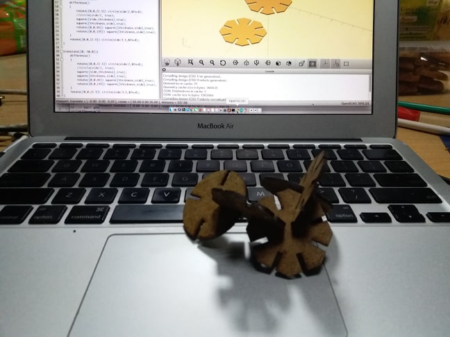
Working with OpenScad is especially handy for reuse of modeled graphical elements on one side and parameterizing parts thereof.
Here i made a hexagon from a single big square substracting 4 squares from it under different angles and folloing by adding a circle in the center.
difference()
{
    rotate([0,0,22.5]) circle(side/2,$fn=8);
    //circle(side/2, true);
    square([side,thickness],true);
    square([thickness,side],true);
    rotate([0,0,45]) square([thickness,side],true);
    rotate([0,0,135]) square([thickness,side],true);
}
rotate([0,0,22.5]) circle(side/3.5,$fn=8);
It uses the parameters here to define size and kerf which should be machine kerf + material thickness + a margin (+/-) for the tightness of the fit
side=40;


material=2;


kerf = 0.05;


margin=0;


thickness=material+2*kerf+margin; // center cut normal fit
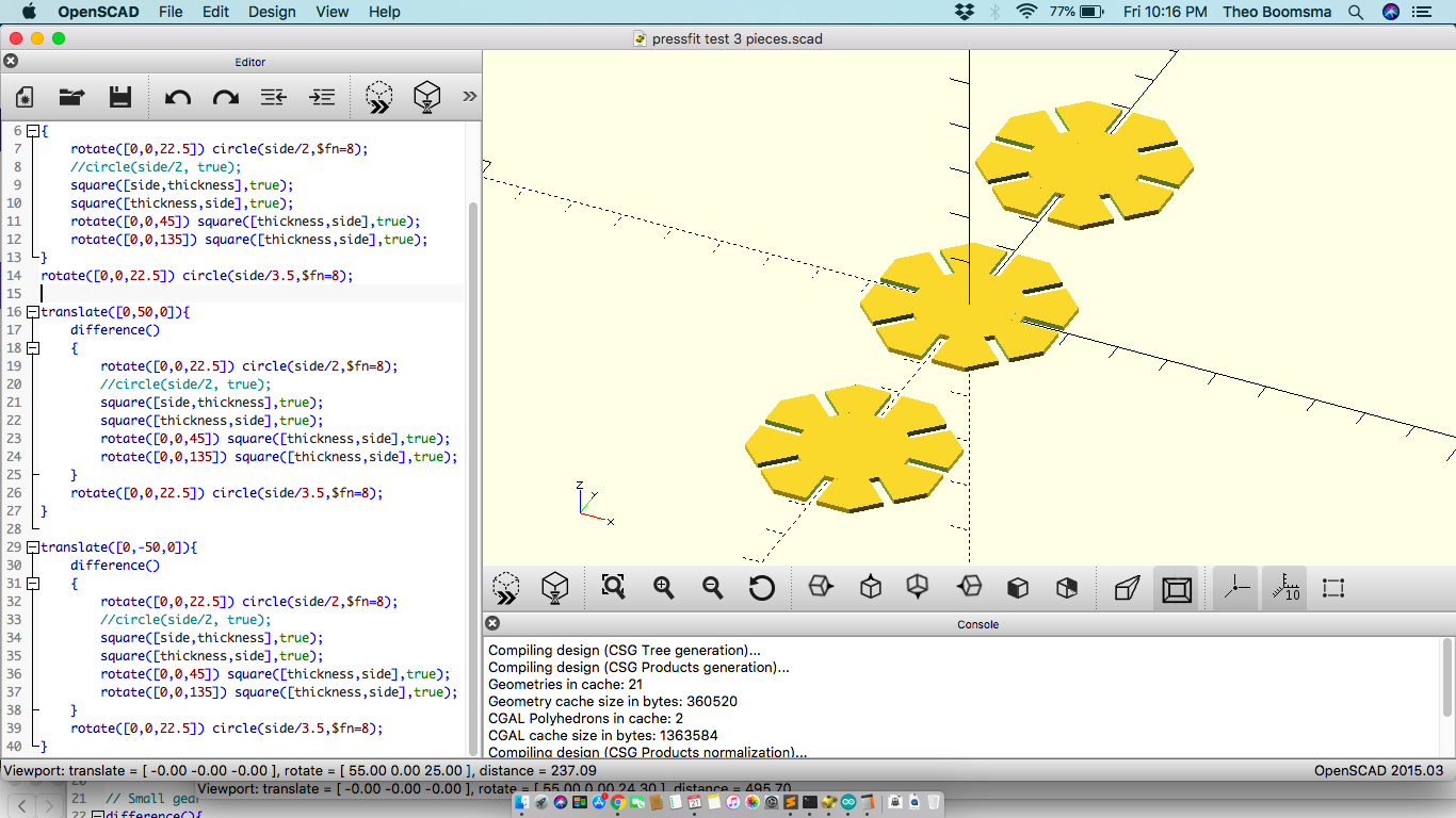
To view your updates click on F5 to render it

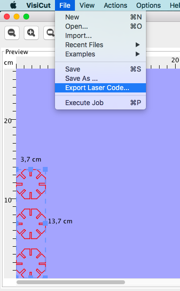
The contours are generated for flat cutting in laser cutter. We export the file to SVG or DXF format. DXF is preferred as the original dimensions often get lost when importing the SVG file into Visicut, the software to do preparation for Laser Cutting with.
So click on >>File>> Export >> export as DXF>> now save the file in your designated folder.
We open Visicut now to do CAM or preparation for manufacturing by generating GCode file
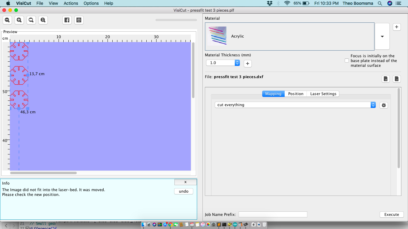
Here we can still change the orientation of the parts to be printed or even duplicate of we need more copies in a single run.
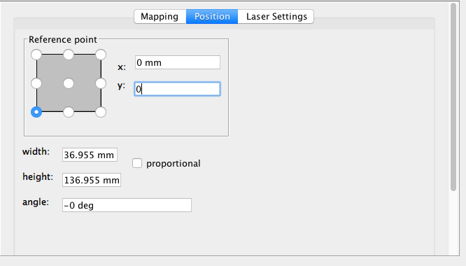
On the right side of the screen you set your laser for this cut.
Change the reference coordinates for start of your cut.
Set the laser power and feed
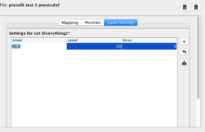
Now export the gcode to a file.
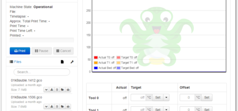
In Kazlab the laser is controlled via a print server (OctoPi software on a raspberry pi) that serves as a Jog pendant and file repository for to be printed gcode files.
Connect with your web browser to http://192.168.1.24 (the Kazlab laser address) and select upload file to upload your file to the queue.
Setup your workpiece material on the laser cutter based on your selected orientation.
Calibrate the height of you laser head with special spacer by bringing up or down the laser bed vi the Z-axis on the pendant. Keep in mind that the response times for the laser are quite long
Select your file and jog the laser head to where you want to start your cut. Close the laser enclosure, put on safety glasses and select “print”
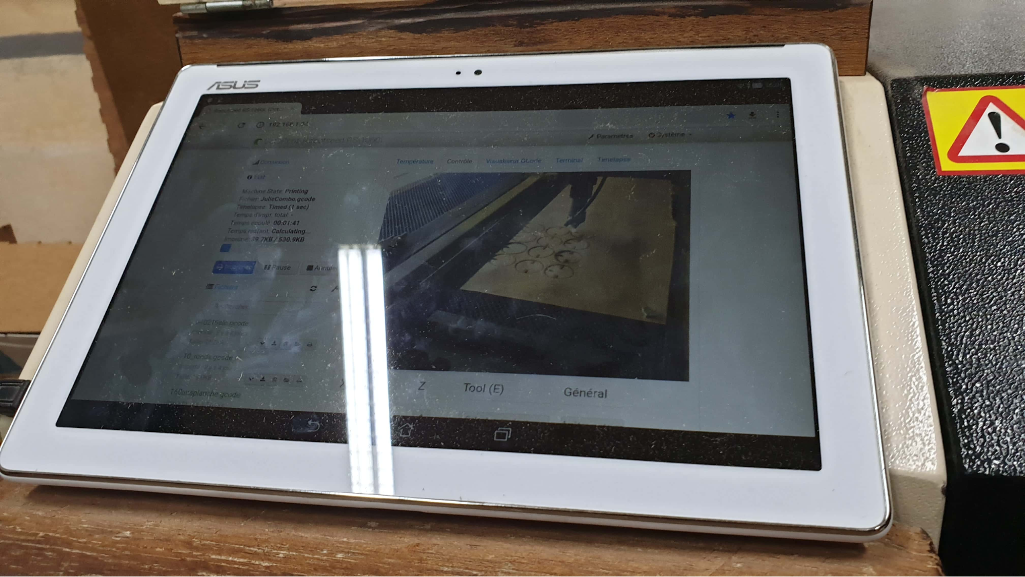
After cutting wait a few minutes before opening the lid again.for fumes to be extracted by the blower system.
The result of my print fitted together here
Important laser facts
We initially tried 80% power to do our initial test cut but it was not enough to cut through the mdf - we should use 95%power
Keep in mind the sequence of starting the laser cutter
1.Extract Air
2.Water Chiller
3.Power Button
4.User Interface
Laser cutters need in regular maintenance
- if u use the lazer too long it won’t be as effective so take a break
- clean mirror and lens with alcohol or acetone (the lens works only on one side so make sure you put it back properly).
- Clean lenses and calibrate your laser weekly.
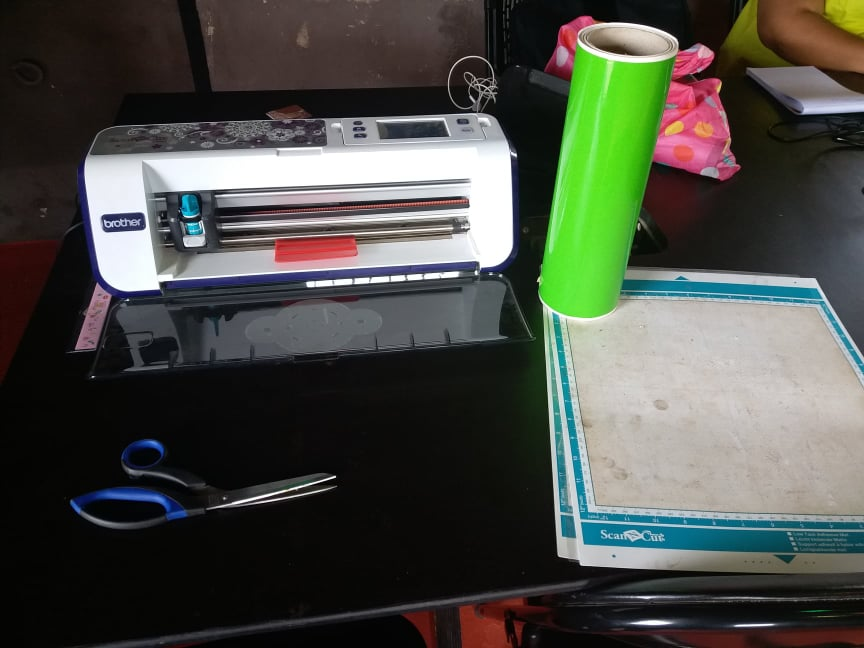
Vinyl cutting
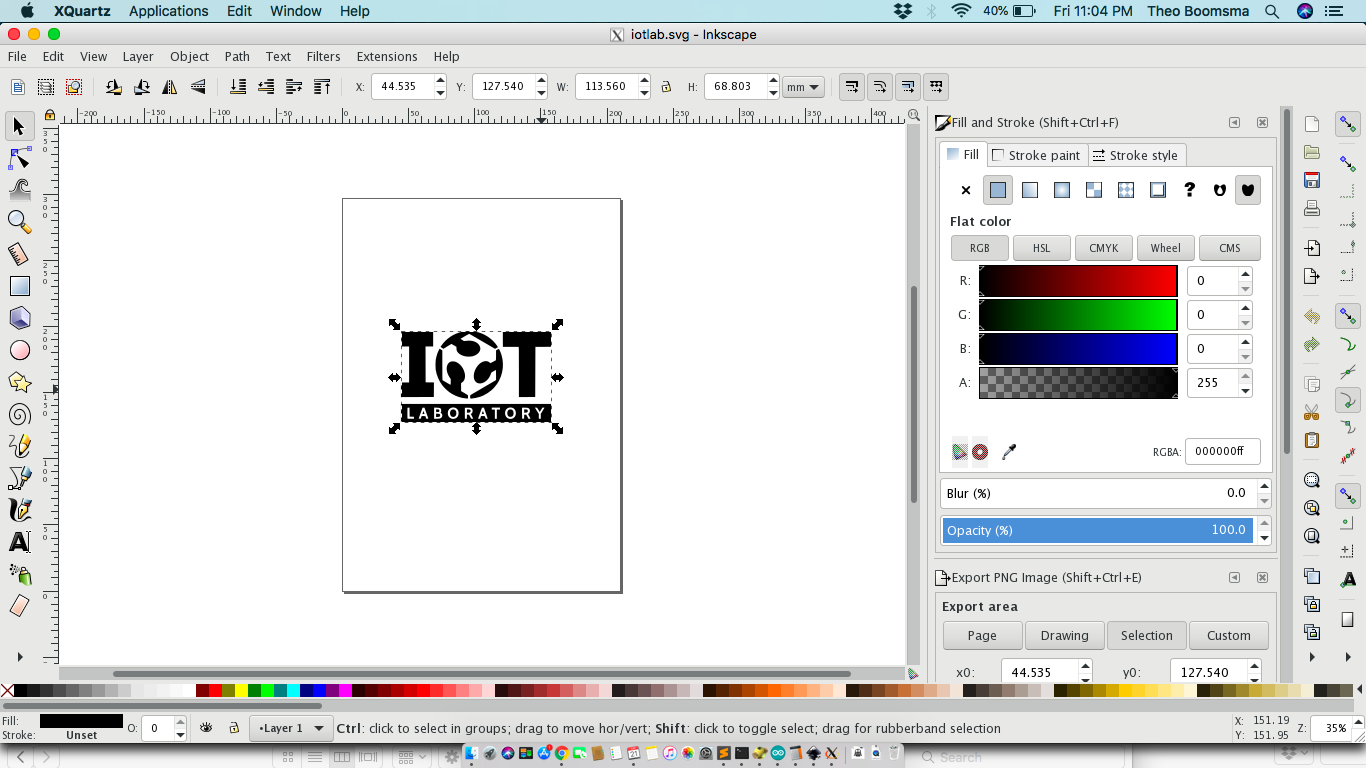
- Make or select what you want to cut first, in my case the IoT Lab Logo that i got from our designer as a PNG file. This is NOT the correct format as we need vector or line graphic for cutting.
- Open the file in InkScape and run \
Path >> Bittrace to make an extra object that traced the outside lines from a bitmap. Move the upper object away and delete the 2d one. You now have a vector image of your bitmap.
- After that remove the fill on my image (image will disappear probably)and then go to the Stroke/style tab and make the stroke fill 0.200
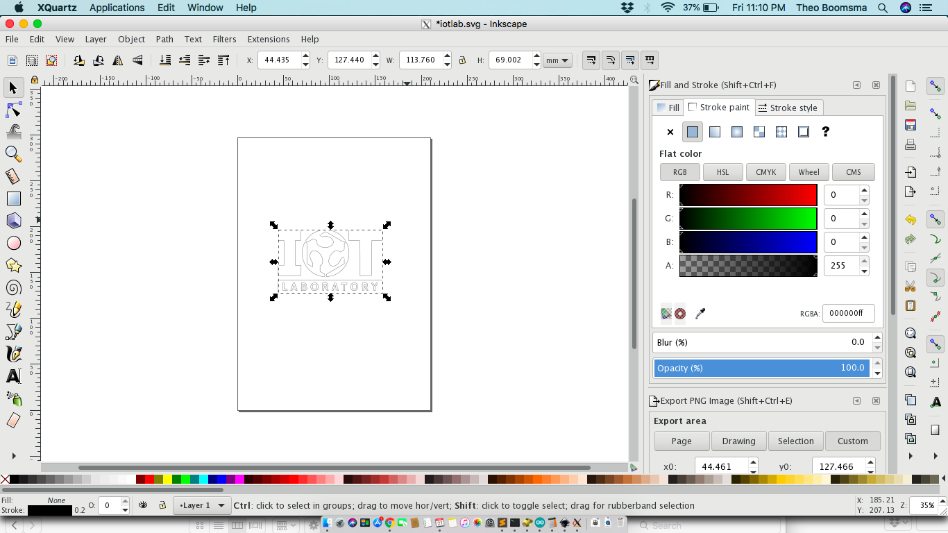
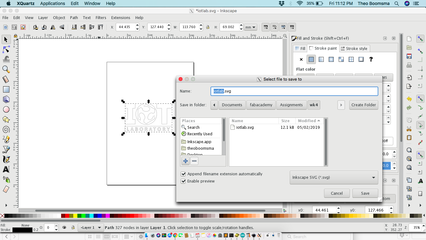
- Save file to svg format.
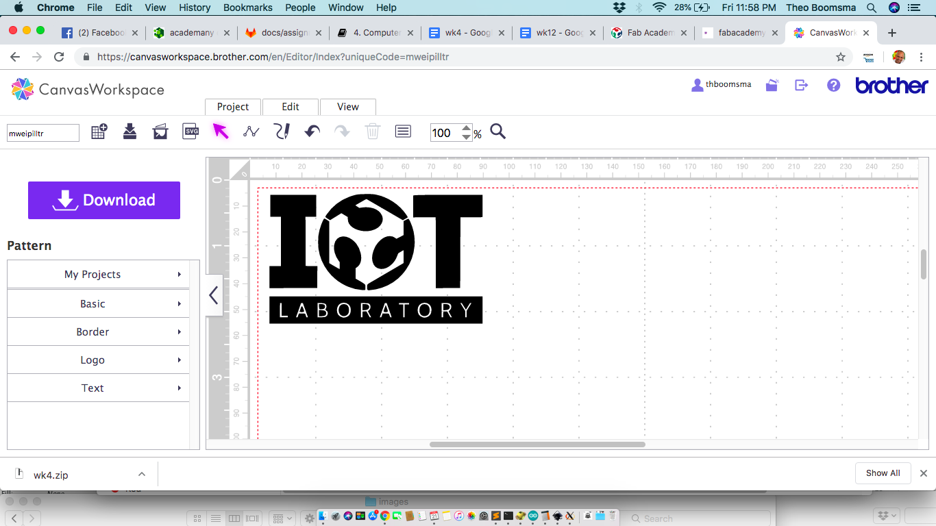
Now i opened the CanvasWorkspace online to upload the svg files and to convert file from svg to fcm so that our vinyl printer could read the file. Then downloaded the file and save to a memory stick
- Load the memory stick into the Brother machine and set your workpiece material, the vinyl foil on the machine template with some tape
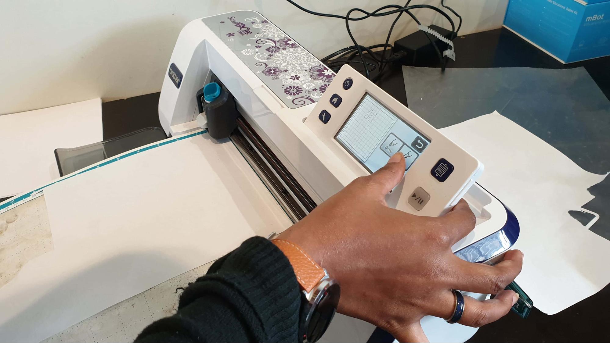
- Open the machine console and naviaigate t your file on the memory stick and selected it.
- To take out your vinyl peel out the unneeded parts of your design with a small tweezer. Add the transfer film over your design and peel the cut design over to the transfer film by helping the pieces carefully migrate over.
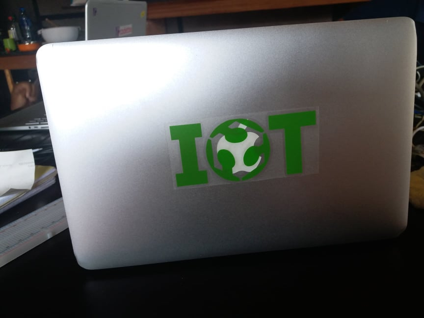
Now it’s time to move letters or logo from transfer file to your object of choice. Clean and degrease the surface first.
Here’s an image of my new mac logo
Important
For good results when cutting vinyl the knife pressure should be just right, the sweet middle between not ripping foil apart and not cutting it deep enough. The cutter head allows for this via spring pressure.
Downloads
Zip file contains:
Laser OpenSCAD / DXF / gcode files
Vinyl cut Bitmaps & vector graphics