14. Networking
- Group assignment http://fabacademy.org/2019/labs/lakazlab/assignments/week14/
- send a message between two projects
- Individual assignment
- design, build, and connect wired or wireless node(s) with network or bus addresses
Objectives
- [x] Described your design and fabrication process using words/images/screenshots, or linked to previous examples.
- [x] Explained the programming process/es you used and how the microcontroller datasheet helped you.
- [x] Outlined problems and how you fixed them
- [x] Included original design files and code
- [x] Add link to the group assignment.
- [x] Screenshots and description of the process of creating your board.
- [x] Screenshots of soldering and debugging process.
- [x] Describe the programming of the board.
- [x] Photos or videos of your board working.
- [x] Describe any errors or problems with the process and how you fixed them.
- [x] Include all the files you created for download.
Building an ESP32 prototyping board
My individual project i will build a prototyping board around the ESP32 that hosts virtual comm ports for attached serial devices over the TCP/IP.
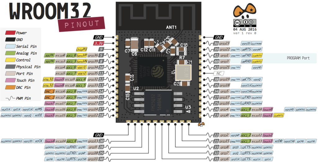
I use the ESP32 development Module WROOM32 and my focus will be to allow most of the break-out pins to be accessible for further testing and prototyping. As an extra i want to allow serial connected devices to communicate via the internet as Virtual COM ports.
Aim is to build a break-out similar to this to enable flexible way of testing ESP32 capabilities for future projects. Projects like the wireless CNC nodes (Jake’s projects)
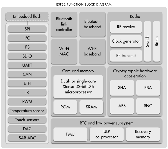
The ESP WROOM32 module
- Processors:
- Main processor: Tensilica Xtensa 32-bit LX6 microprocessor
- Cores: 2 or 1 (depending on variation) \ All chips in the ESP32 series are dual-core except for ESP32-S0WD, which is single-core.
- Clock frequency: up to 240 MHz
- Performance: up to 600 DMIPS
- Ultra low power co-processor: allows you to do ADC conversions, computation, and level thresholds while in deep sleep.
- Main processor: Tensilica Xtensa 32-bit LX6 microprocessor
- Wireless connectivity:
- Wi-Fi: 802.11 b/g/n/e/i (802.11n @ 2.4 GHz up to 150 Mbit/s)
- Bluetooth: v4.2 BR/EDR and Bluetooth Low Energy (BLE)
- Memory:
- Internal memory:
- ROM: 448 KiB \ For booting and core functions.
- SRAM: 520 KiB \ For data and instruction.
- RTC fast SRAM: 8 KiB \ For data storage and main CPU during RTC Boot from the deep-sleep mode.
- RTC slow SRAM: 8 KiB \ For co-processor accessing during deep-sleep mode.
- eFuse: 1 Kibit \ Of which 256 bits are used for the system (MAC address and chip configuration) and the remaining 768 bits are reserved for customer applications, including Flash-Encryption and Chip-ID.
- Embedded flash: \
Flash connected internally via IO16, IO17, SD_CMD, SD_CLK, SD_DATA_0 and SD_DATA_1 on ESP32-D2WD and ESP32-PICO-D4.
- 0 MiB (ESP32-D0WDQ6, ESP32-D0WD, and ESP32-S0WD chips)
- 2 MiB (ESP32-D2WD chip)
- 4 MiB (ESP32-PICO-D4 SiP module)
- External flash & SRAM: ESP32 supports up to four 16 MiB external QSPI flashes and SRAMs with hardware encryption based on AES to protect developers’ programs and data. ESP32 can access the external QSPI flash and SRAM through high-speed caches.
- Up to 16 MiB of external flash are memory-mapped onto the CPU code space, supporting 8-bit, 16-bit and 32-bit access. Code execution is supported.
- Up to 8 MiB of external flash/SRAM memory are mapped onto the CPU data space, supporting 8-bit, 16-bit and 32-bit access. Data-read is supported on the flash and SRAM. Data-write is supported on the SRAM.
- ESP32 chips with embedded flash do not support the address mapping between external flash and peripherals.
- Internal memory:
- Peripheral input/output: Rich peripheral interface with DMA that includes capacitive touch, ADCs (analog-to-digital converter), DACs (digital-to-analog converter), I²C (Inter-Integrated Circuit), UART (universal asynchronous receiver/transmitter), CAN 2.0 (Controller Area Network), SPI (Serial Peripheral Interface), I²S (Integrated Inter-IC Sound), RMII (Reduced Media-Independent Interface), PWM (pulse width modulation), and more.
- Security:
- IEEE 802.11 standard security features all supported, including WFA, WPA/WPA2 and WAPI
- Secure boot
- Flash encryption
- 1024-bit OTP, up to 768-bit for customers
- Cryptographic hardware acceleration: AES, SHA-2, RSA, elliptic curve cryptography (ECC), random number generator (RNG)
More details about the IO here
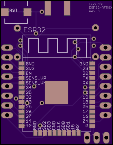
Designing the board
Lets design the board with a few basic design elements to keep in mind.
- Regulated power (1A 3.3V)
- All required for prototyping pins should be broken out
- The WiFi antenna to be added on board but as far out of the way of other active components (preferably overhanging the side of the host board.
- Communication lines available (I2C, SPI, Serial)
- GPIO’s
Design guides for the ESP32 can be found here
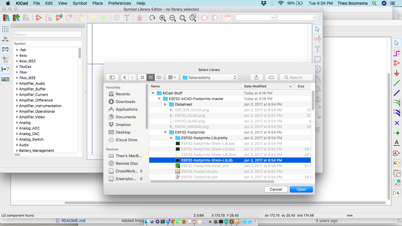
First i downloaded the Footprints & Schematics for the ESP from here
Added the Library to KiCAD via the Library Manager
The design for break-out board is very basic, connect as much I/O
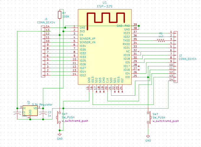
I added added a voltage regulator so we could operate this unit in any environment from 3.3 to 12V and also added 477 ohm resistor in the TX line for filtering as advised in the design manual.
Adding a Micro-USB and Logic level converter from Instructables
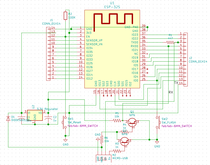
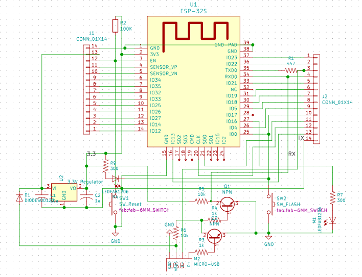
Adding a leds for “mighty blink sketch” and programming mode status led
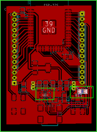
PCB Board design
First of course is to assign the footprints.
Why don’t we have simple (SMD) transistors in the Fab inventory?
Anyway you could find the footprints of many components here
Had to add some 0 ohm resistors to solve some ground plane bridging issues so went back to add a few in parallel to the “to be bridged lines”. In this case the Transistor and the Regulator capacitor.
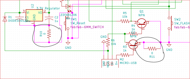
So i could connect the ground plane to the other zone. Here is the final PCB design
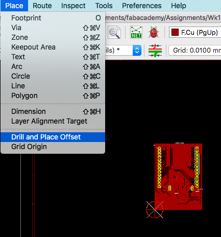
Milling & Soldering
Prepare your KiCAD file by placing origins, auxiliary axis and tool offset markers
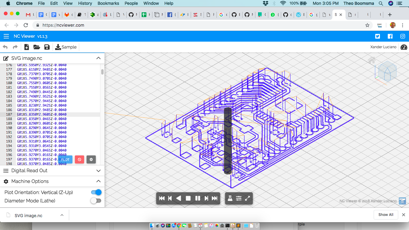
Plot the gerber files via “PLOT” function. Select the traces, dimensions layers. Also clicked on the “generate drill file” to make the holes for my breadboard headers.
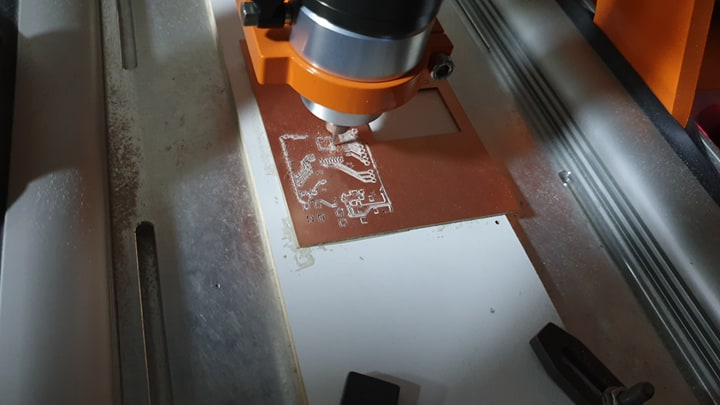
I will not get into too much details about production of the board as i did already in previous weeks. Important is the outcome of the small pitched traces required for the ESP module.
Testing the paths in NCViewer
CAM in flatcam
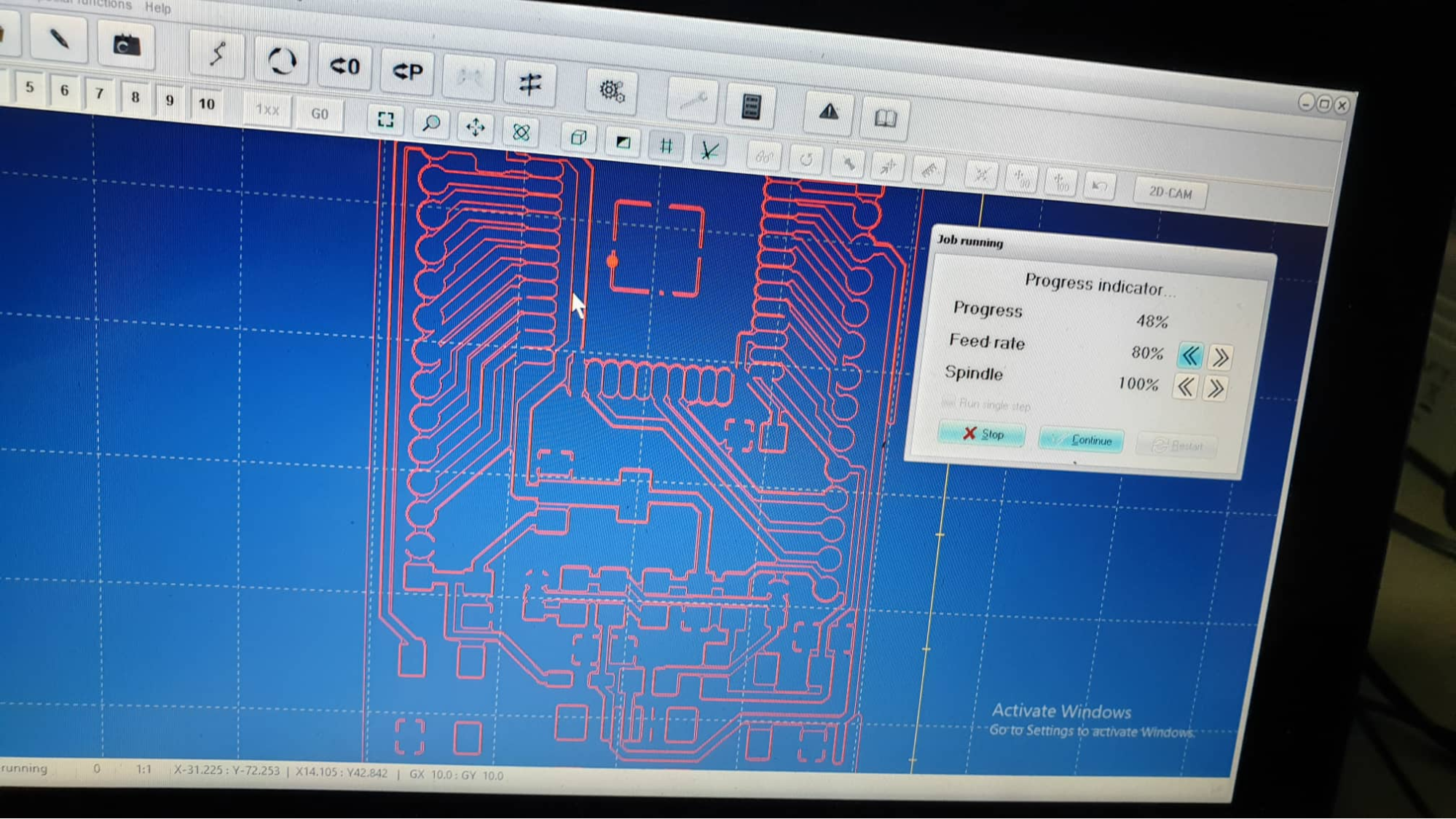
Milling with WinPCNC
Bread-board Headers
From KiCad i had exported drill holes and imported them into FlatCAM and generated nc files also.
The mill simply kept ripping the copper pads off. After a few tries with the milling i realized that the drilling had to be done without the “milling” option selected and just the “drill” option. This way at least i could make the holes straihght down with the finest drill i had. At least the tracks didnt get ripped and i have a template for drilling the holes manually if required with a dremel to size.
Soldering
Soldering i have done with solder paste and heat reflux process. That process is simple and clean especially with extremely small traces on your MCU. Can’t live without it anymore.
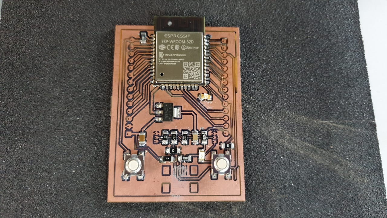
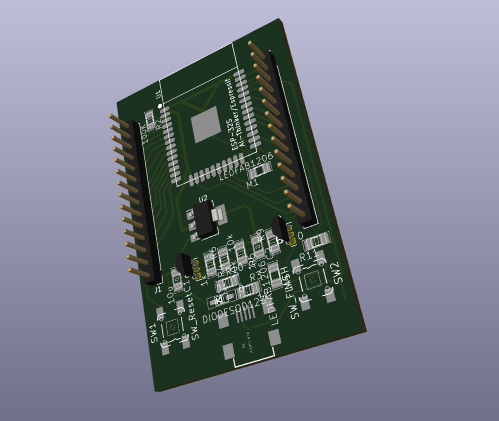
After all mods/hacks and tweaks described later the final board looked like this (without the breakout headers)
Programming the ESP32
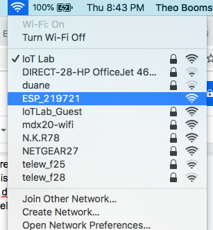
Happy that i installed the reset and flash buttons, so after firing up i just pressed both switches and the ESP appeared on WIFI network as an AP.
I will follow the instructions from https://lastminuteengineers.com/esp32-arduino-ide-tutorial/ to get it started now.
For the Arduino IDE follow this link
https://github.com/espressif/arduino-esp32/blob/master/docs/arduino-ide/boards_manager.md
Problems & Fixes
Pull-up on the Flash pin
Another problem is that i forgot to install a pull-up on the Flash pin GPIO0 to prevent firmware loss. I did however have a led installed when the board goes into flash-mode. Unfortunately it only works while pressing the flash button, but it doesn’t stay on whent entered into Boot mode.
Access to Micro USB
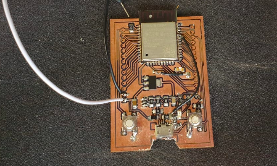
Obviously i was misled by the naming in the KiCAD libraries, just picking a micro-usb without checking the actual footprint compared to the offered one in the Fab library. Looked like i got the same footprint of the Mini USB instead. Too late to fix so just worked with what i had. Soldered by opening the pins up bit and space the socket with a 0 ohm resistor under it so the planned TX line could still pass under the socket.
Eventually no usb adapter cable could fit into the setup so i made a cut out to facilitate.
Serial port Logic converter issue
Problem with the serial connection appeared and after researching it i realized that the used footprints for SMD transistors had a completely different pinout than the standard NPN transistors, and was also NOT connected through to the ESP32 chip RX port.
Another this is that i implemented a bi-directional logic level converter which is totally useless also for just a uni-directional RX channel. So actually that whole part of the schematic became useless and i decided to fit in a simple voltage bridge on the RX line where i could fit it in and also add a bridging cable. That worked fine
ESP HAS NO USB management built in
Connecting the ESP32 via on USB (RX/TX) does NOT show any device in your USB devices list. I realize now that i should have added a USB/UART controller for that functionality. Its abit late but for now so i will install an improvised FTDI header so we could at least install firmware on it.
Next version of the board i will include the USB controller so we could upload via USB directly like all prototype boards seem to have (should have noticed the CP2101 on every ESP development board i got my hand on).
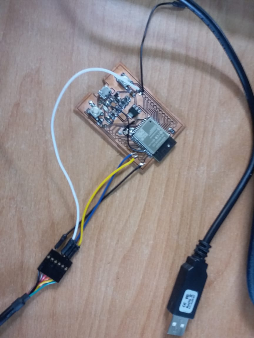
Improvised FTDI connection
Yes connected to ESP32
Problems flashing
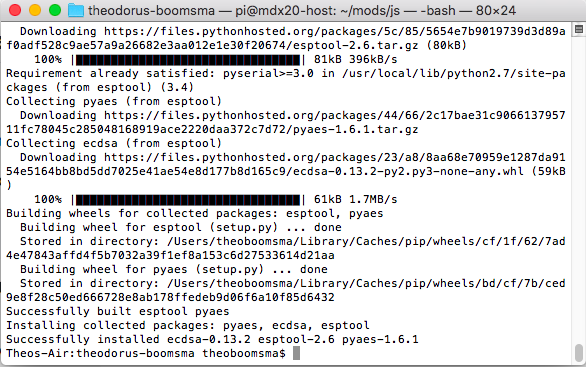
Install the ESP Flashtool https://github.com/espressif/esptool
Update the firmware
After this we should be able to install the firmware via Arduino IDE.
Boot flash switching issues
https://github.com/espressif/esptool/wiki/ESP32-Boot-Mode-Selection
As well as GPIO0 and GPIO2, the following pins influence the serial bootloader mode:
| GPIO | Meaning |
| 12 (MTDI) | If driven High, flash voltage (VDD_SDIO) is 1.8V not default 3.3V. Has internal pull-down, so unconnected = Low = 3.3V. May prevent flashing and/or booting if 3.3V flash is used and this pin is pulled high, causing the flash to brownout. See the ESP32 datasheet for more details. |
| 15 (MTDO) | If driven Low, silences boot messages printed by the ROM bootloader. Has an internal pull-up, so unconnected = High = normal output. |
Fixing the boot mode cycle issue
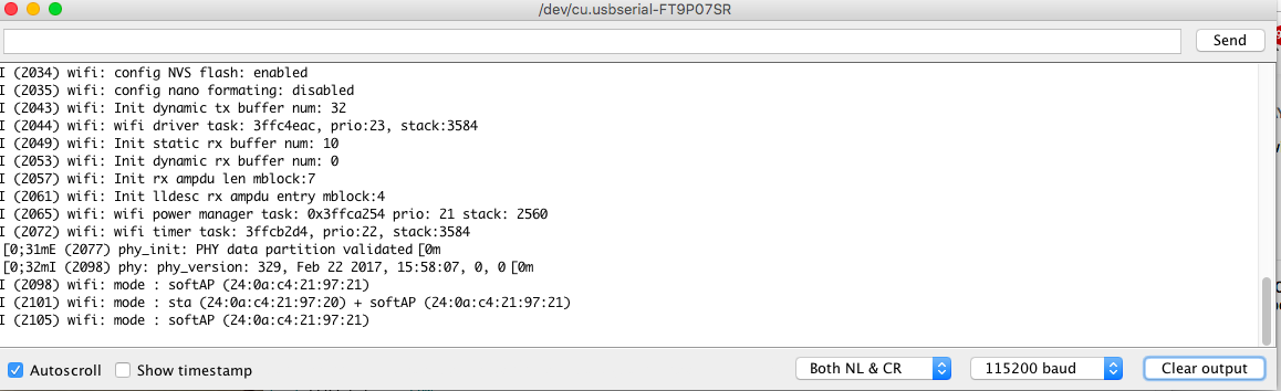
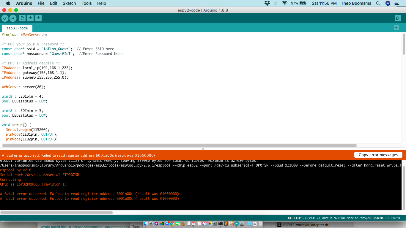
The behaviour of the ESP32 module NOT going into flash mode is widely discussed on the internet. I tried many of the fixes but the one that worked was the advice to add a 2.2uF capacitor between the EN pin and the GND from this source
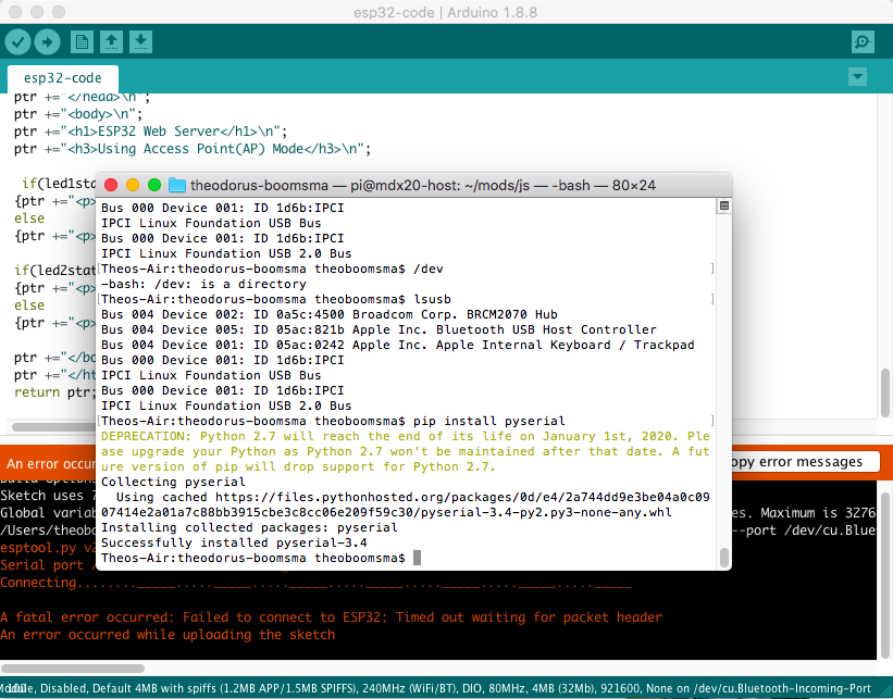
Now we got connection to the ESP and another error pops up
FTDI Driver update
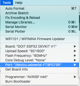
The last hurdle was fixing the error above. I had to update my Mac’s FTDI drivers and finally firmware uploads work.
OTA firmware management
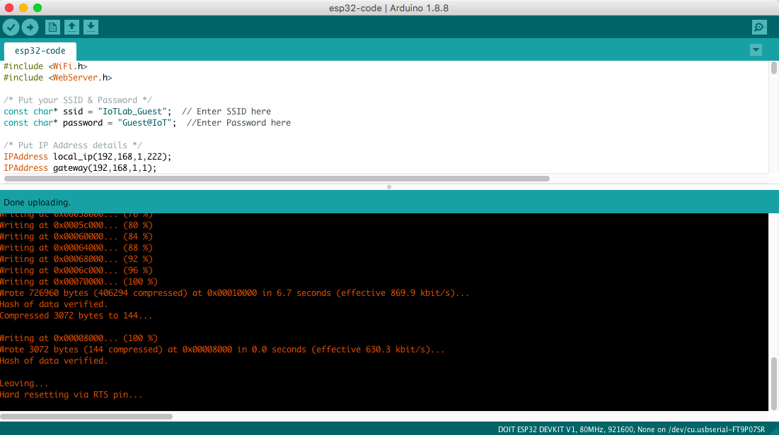
I added OTA drivers to allow for Wifi uploading of firmware by adding the OTA Handler to your code. Ofcourse you also need Wifi Access and in this case i made the unit a WiFi Access Point (AP mode)
include 
The device shows up in your Arduino IDE as soon as you connect to the just created WiFi AP.
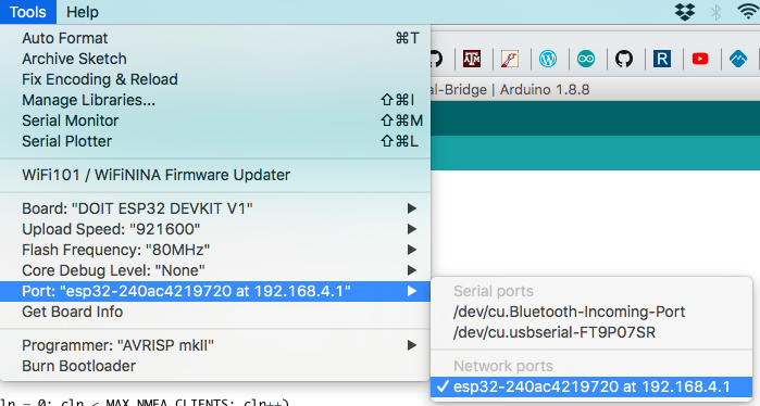
We can now upload firmwares over Wifi to the ESP32 device!
Virtual COM ports
So how about connecting MCU’s that are connected via UART behind this ESP32?
It would be very nice (and handy) to use the ESP32 as a data AND configuration/firmware gateway, via a set of virtual COM ports. My ESP32 will host these Virtual COMs allowing us to connect to directly connected serial devices (like a set op Motor controllers of the like).
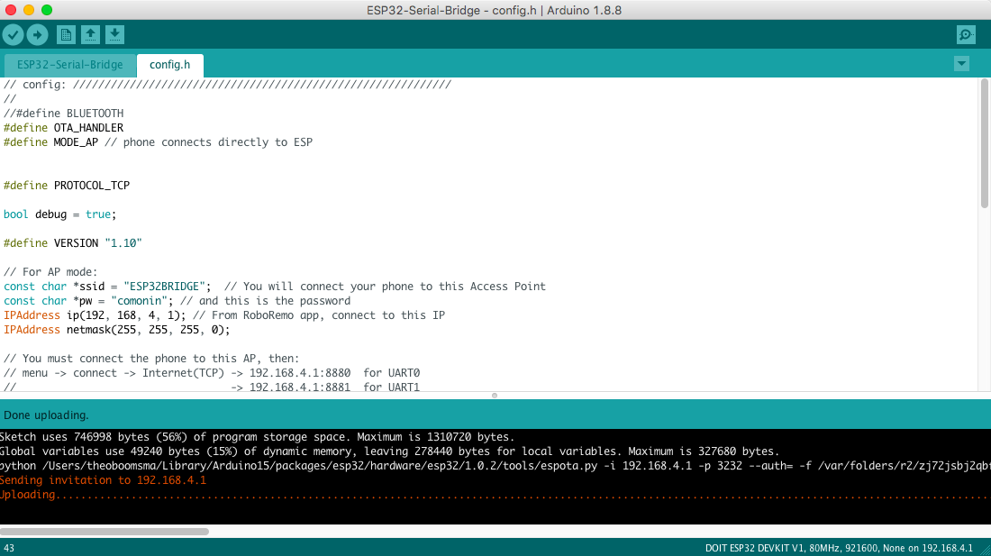
I will be using the Triple Serial bridge on for ESP32 as baseline project. Download and edit config.h and upload to your device. A fork for ESP8266 is available here a Wifi-Serial for ESP8266
Connect some device on one of the 3 ESP32 serial ports:
192.168.4.1:8880 <-> COM0 : Rx -> GPIO21 / Tx -> GPIO01


192.168.4.1:8881 <-> COM1 : Rx -> GPIO16 / Tx -> GPIO17


192.168.4.1:8882 <-> COM2 : Rx -> GPIO15 / Tx -> GPIO04
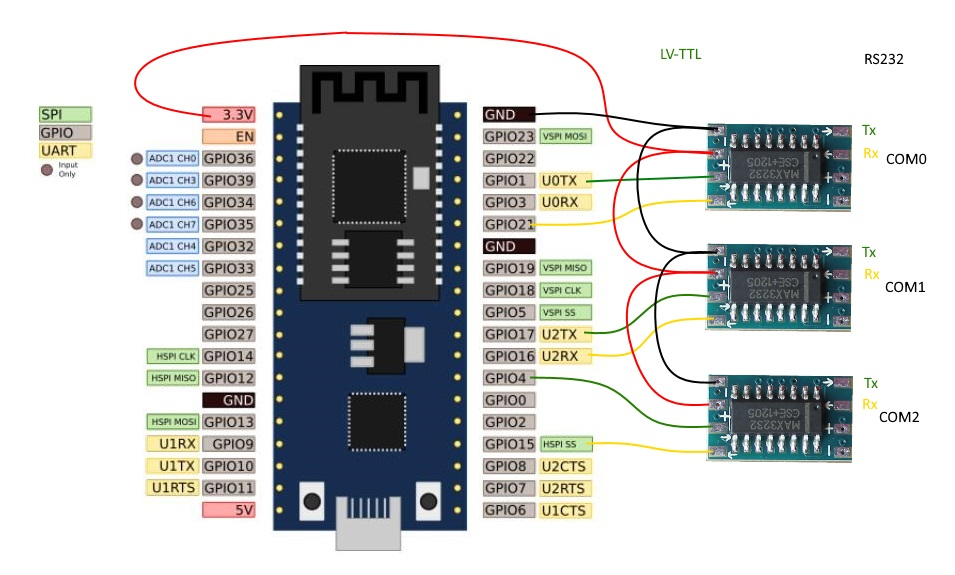
Pin layout for the COM ports
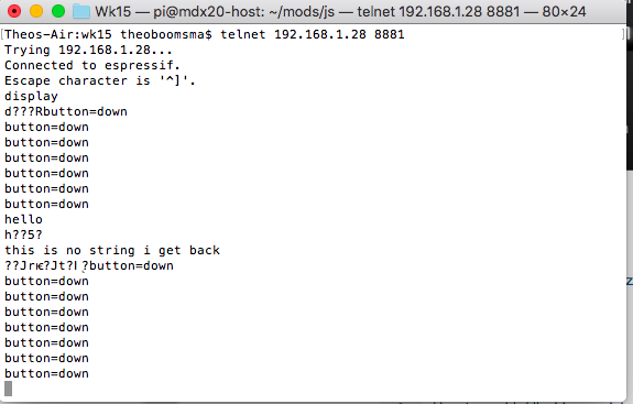
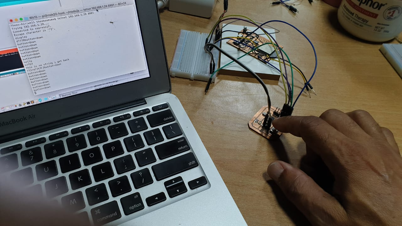
For the test i will connect my old hello-world board and connect it to serial COM1 on the ESP32 (192.168.4.1:8881 <-> COM1 : Rx -> GPIO16 / Tx -> GPIO17) and test the functionality by connecting and uploading a sketch to it.
The sketch uploaded to the Hello World board sends a serial message as soon as the button is pressed also it echo’s any text received (in ASCI). This serial message should be relayed via the ESP32 to the LAN network on 192.168.4.1:8881.
The connection to the virtual Com post can be made via Putty or in my case telnet.
Telnet IP_Address_of_ESP32 8881
This actually really cool for deploying IoT solutions and older devices that only communicate via serial ports. I would explore this also maybe for virtual I2C to control and sync multiple stepper controllers over WiFi.
Files & Downloads
Files included:
- ESP32 Schematics & proto board design
- ESP Wroom32 Firmware
- ESP32 Virtual Serial
- HelloBoard firmware
References
ESP Flash Tool https://github.com/espressif/esptool
About the boot mode https://github.com/espressif/esptool/wiki/ESP32-Boot-Mode-Selection
ESP Virtual Serial port: Triple Serial bridge on for ESP32
ESP8266 Virtual Serial Wifi-Serial for ESP8266