18. Wildcard week
For Wildcard Week I have chosen to create a composite. I reviewed the 2018 Wildcard Week video to get a better understanding of the composite assignment.
Ideation
After considering several different composite projects, including fabricating the body of a drone (for which I would later 3D print the propellers and necessary “wing” attachments), I decided on fabricating the seat and back of a chair that I would make from a composite of burlap and epoxy resin.
What I need to learn to fabricate
Design: Right away, I knew I wanted to create a smooth, curved 3D surface. That will require learning 3D surface modeling (FUN!!! I’ve been eager to get good at that). Also, I’m choosing to create a skin over a skeleton frame. I’ll need to use a “slicer” on my CAD model to create the frame.
Fabrication: My idea is to laser-cut cardboard to create the frame (from the CAD model). Then, I’ll layer the composite as a skin over the frame. I’m choosing to go this route out of necessity, as our lab’s ShopBot needs servicing at the moment. Otherwise, I would have created a mold in the shape of the components, and used compression to complete the composite. In any case, this will be a fun experiment. I’ll cover the skeleton of the frame with the composite fabric and matrix, then use a vacuum for the resin compaction. Listening to Neil’s advice, I’ll need to be conscious of the heat generated during compaction to avoid melting the vacuum bag that will be used.
Research
Curved 3D Surface Modeling: - YouTube: How to model bends in Fustion 360
This video introduced me to the basics of creating curved 3D surfaces with thickness.
- YouTube: How to Surface Model a Shoe Horn in Fusion 360
I chose this video because it showed me how to generate curvature in more than a single direction.
3D Model to 2D Vector/Slicing: - YouTube: Slicer for Fusion 360 - YouTube: Making-3D Model to 2D Vector
Design
My first step in design will be to get rough measurements from an existing chair to base my CAD model on.
Measurements
These are very rough measurements of the dimensions of a basic metal foldout chair: - Seat: 16” x 16” x 2” (width x height x thickness) - Seat Back: 16” x 14” x 1” (width x height x thickness) I’ll base my model on these loose measurements and adjust as necessary.
CAD
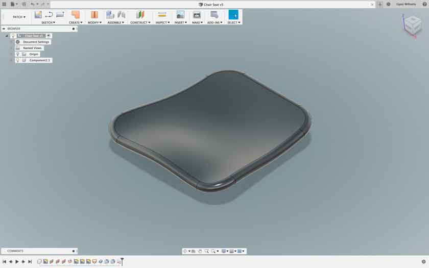
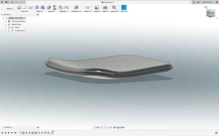
So, even though the CAD tutorials were extremely helpful with designing a 3D curved surface, I still had to do some significant research on constraints to try to solve a problem of maintaining the symmetry of the splines if I wanted to change sketch dimensions at a later time. I didn’t solve that problem, so the design isn’t parametric. Even trying to dimension a symmetrically designed spline after I’d drawn proved beyond my current understanding of the CAD tools in Fusion 360. Nevertheless, this was the first time I had gone beyond the Model workspace in Fusion 360, using primarily the Patch workspace. The tutorials I used for constraints are not linked on this page, but can be found with a search for constraints at the Autodesk website.
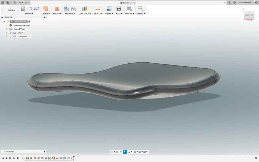
Here are the initial CAD images and file I’ve created for the seat of the chair:
- Chair Seat Fusion File
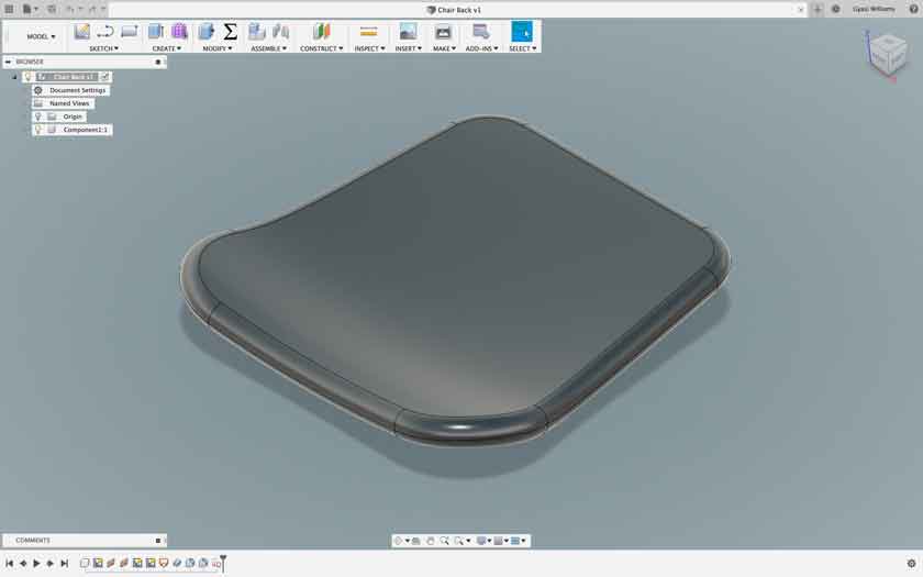
…and for the back of the chair:
- Chair Back Fusion File
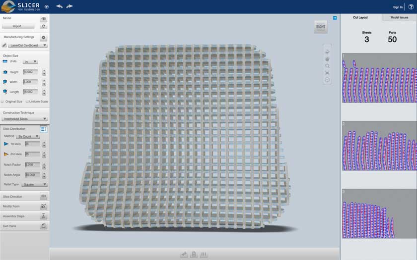
In order to have the frame cut from cardboard, I need to convert the CAD data from Fusion into slices that can be used on a laser cutter (Epilog Fusion M2 32 CO2 Laser System). The first step was downloading Slicer for Fusion 360. After a quick tutorial, I was able to use the add-on pretty easily, as it is very intuitive. A word of caution when using Slicer: the program will alter the dimensions of your design, so be sure to watch out for that when entering dimensions into the slicer.
Here are the slicer files and pdfs for the cardboard frame of the seat and back of the chair:
- Chair Seat Slicer File

Fabrication
- Epilog Fusion M2 75W CO2 Laser
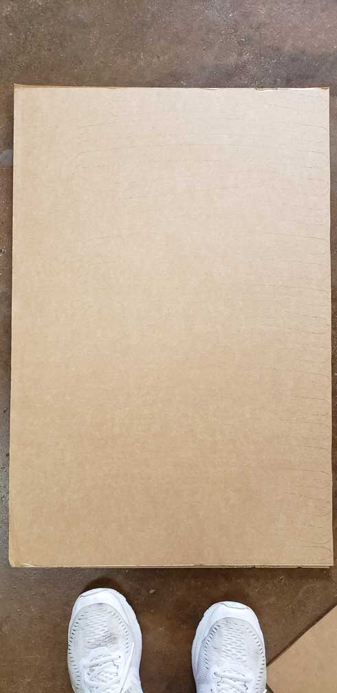
It’s been a while since I used the laser cutter, so taking time for a little refresher on how to operate it, lol. In planning for the frame cutting, I set up my slices to be cut on 20”x30” pieces of cardboard, knowing the size of the laser cutter table is roughly 20”x32”. My cardboard is 30”x40”x3/16” in size, so I simply cut 3 full size pieces of cardboard in half, giving me the 6 pieces of 20”x30” cardboard that I need to fabricate the internal structure (frame) for the seat and back of the chair.
After reviewing the laser manual, a few YouTube videos and and the Epilog website, I remembered that the laser functions, practically, as a printer, and that once my file was set up in my graphic design software (Adobe Illustrator, in this case), sending the cut path to the laser meant selecting File->Print. Excellent! I saved my cut path files from Slicer for Fusion as PDFs. You could use EPF files as well. I chose the pdf format, figuring the cut lines would be saved as vector images automatically. The choice paid off, as not only were the cut paths saved as vectors, but all of the other (very useful) information (part numbers, e.g. z-4, and notch numbers) are saved as raster information which can easily be skipped over when sending the file to print/cut on the laser.
Steps for sending files to Laser Cutter
- Once Illustrator is open, click “Open” (or File->Open) to open your file.
- In the Properties tab on the upper right of the application, select Edit Artboard (If you see Artboard just below the Properties tab, this happened automatically).
- Set the width(W) and height(H) to the size of your substrate, in the Transform section of the tab. There are 9 square dots, arranged in a square in the left of this section. Make sure you click the dot on the lower left to properly orient the page in preparation for the laser. Illustrator thinks of the substrate like a piece of paper, and orients the dimensions from that perspective.
- Click File->Print, then select “Epilog Engraver…” as your printer. Click Setup to open the printers dialog box.
- With the Epilog Engraver highlighted amongst your printers, click Preferences to go to the laser print settings pop-up dialog box.
- Make sure the following are clicked: Send to Laser, Auto-Focus, Vector Grid, and Vector (button).
- Change the following as needed: thickness (thickness of your substrate), Piece Size (length/height & width of your substrate), and your Vector settings (see recommendations for each substrate in the Epilog manual).
- Click OK, Print & Print to send file to the Epilog Laser.
- Look for your job on the Control Panel, then hit the Go button! **Never leave the Laser Cutter while it is operating. Great way to start a fire ;).
Challenges
Adobe Illustrator: Before I produced successful cuts I had the learn that Illustrator defaults to a center-orientation for printing:
*See the Steps for sending files… above to avoid this mistake.
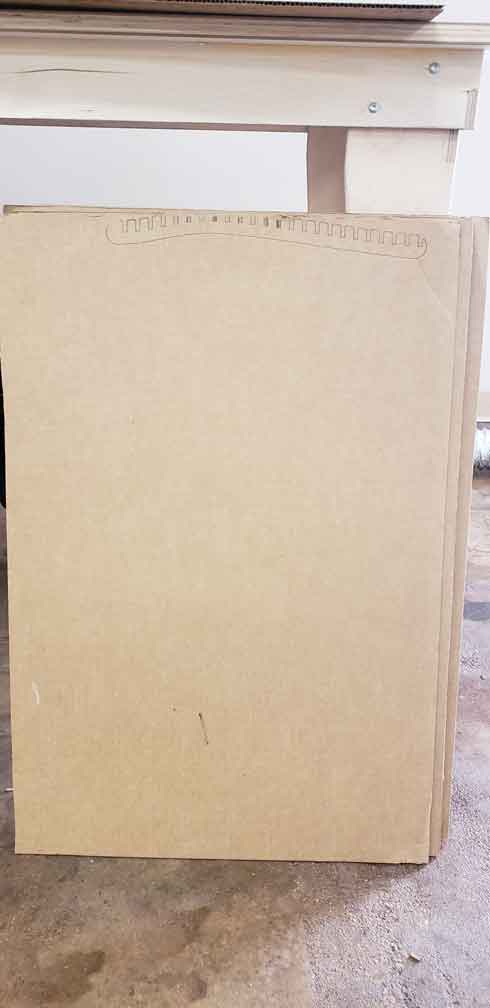
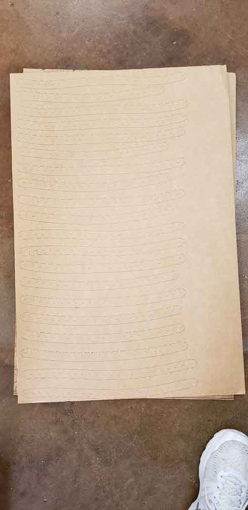
Epilog Fusion Laser Cutting: The manual doesn’t provide specific settings for cardboard (surprising), so I adjusted the settings on each cut to get the laser to cut all the way through the first time without burning the cardboard. As of right now, I’m trying: Speed-25%, Power-45%, & Frequency-80%. Nothing else up to this point (I’m on the 5th of 6 cardboard sheets needed for the frame) has quite done the right job (see images below). I’ll use a razor to remove the pieces when it’s time to assemble it. Update: looks like Speed-25%, Power-50% & Frequency-80% worked well (see last photo). The pieces cut all the way through with just enough connection to hold them in place (adjust as you feel necessary).
- Laser Cut sample images:
Worst laser cut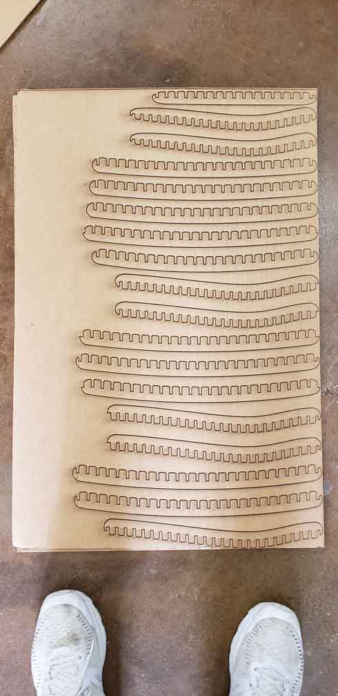
- Best laser cut
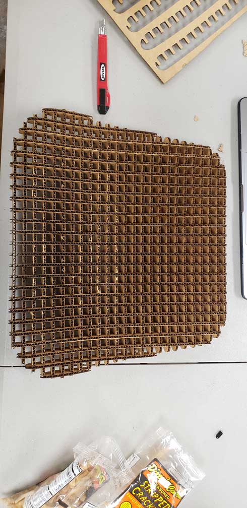
Separation & Assembly: Separating the poorly cut cardboard pieces ended up being a real time-consumer (about 8 hours, when it likely could have been done in 1 hour). I made the mistake of thinking that since my laser cuts were progressively better as I went along that this process would speed up, but I was proven wrong, lol. This part of the process was grueling, to say the least. Lesson: refine the laser cut settings for cardboard on test pieces before cutting your parts and save a day of work.
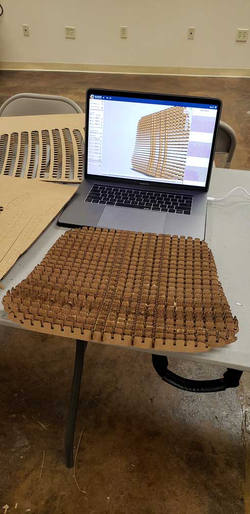
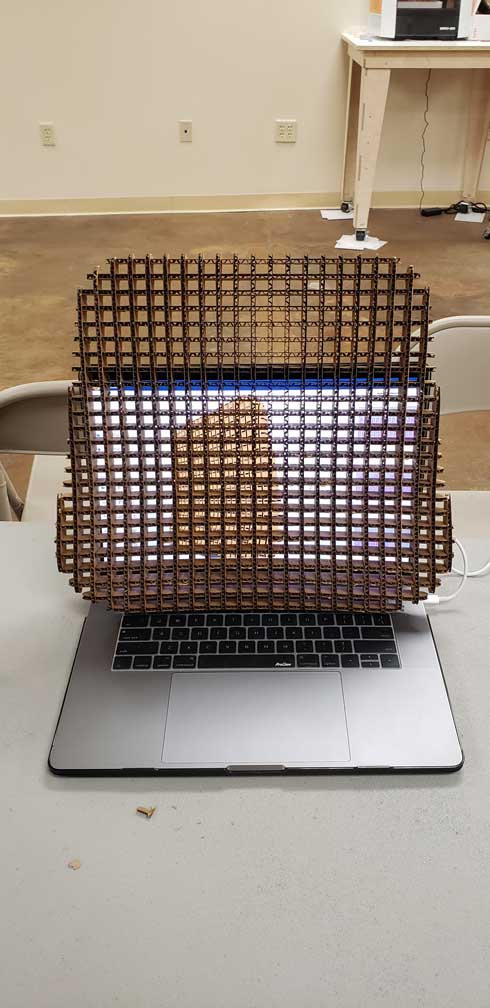
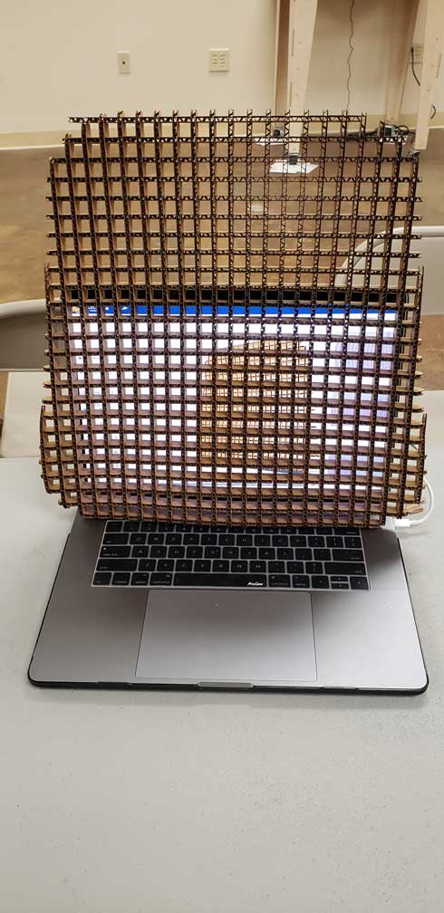
Assembly was much easier, and I like the results:
-
Mid-assembly of the chair back:
-
Fully assembled form images:
Back of the Chair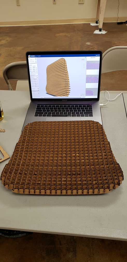
- Seat of the Chair
Creating the Composite
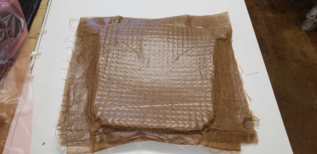
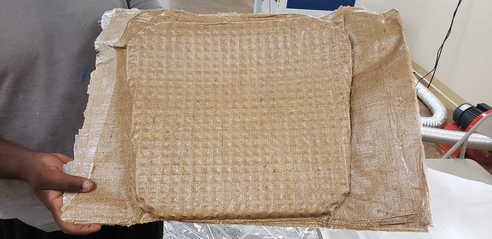
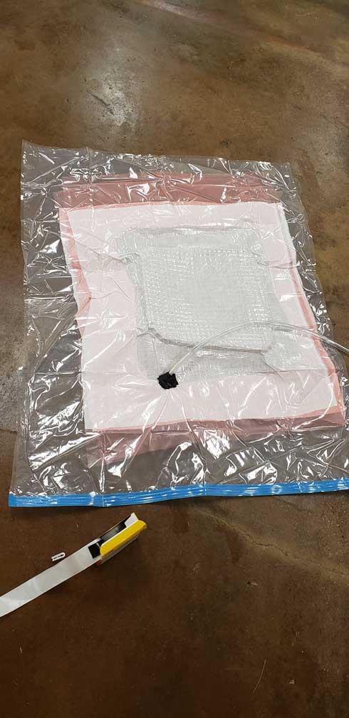
For the first part of my chair, I used three layers of resin-impregnated burlap to cover my chair back form. I used a vacuum pump and bag to cure the form:
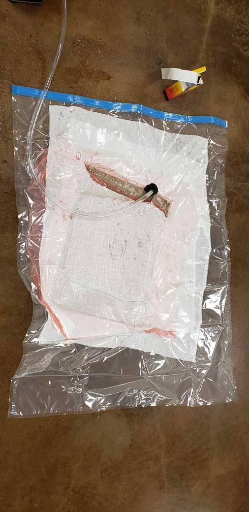
The vacuum was applied for 8 hours, and will need to be removed and excess composite trimmed. Upon first look, I think I could have used more than 3 layers of burlap/resin composite. The cardboard frame, despite the denisty of intersecting cardboard pieces, still had too many gaps (for the 3 layers of composite that I layered) to form a smooth surface. I’ll consider least doubling the number of layers in my next iteration. Either that, or see if creating a mold might be a better process.
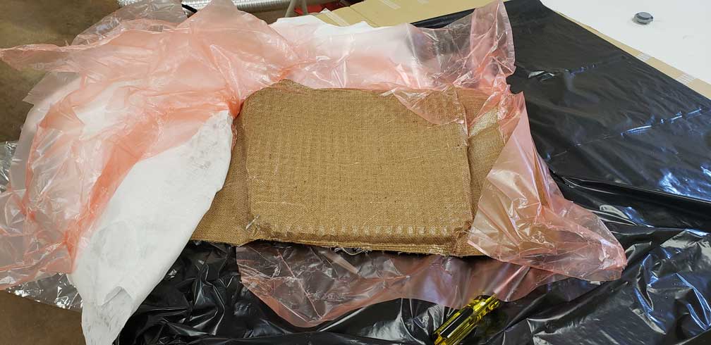
In any case, here are some photos of the composite making for the chair’s seat:
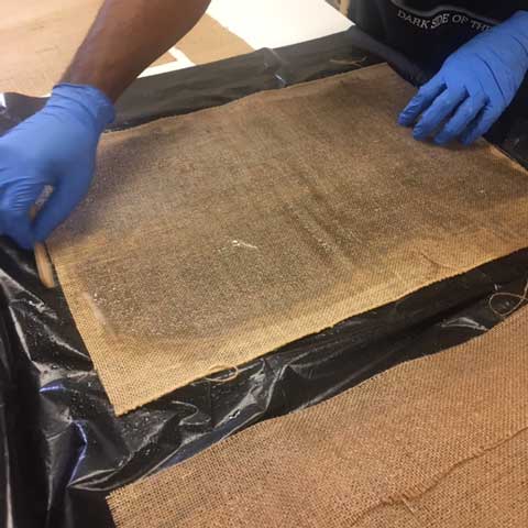
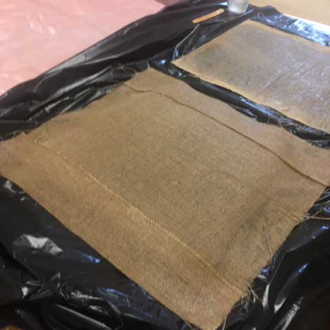
…and the seat after the composite has cured: