Week 5: Electronics production
Group Assignment
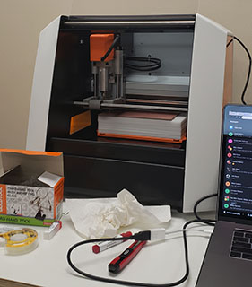
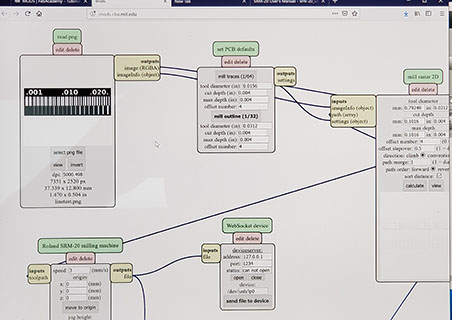
For the group portion of our assignment we “characterized” the design rules for our design process. The first step in this process was testing the precision of the end mills of the Roland precision mill (Roland SRM-20).
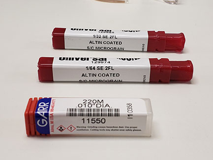
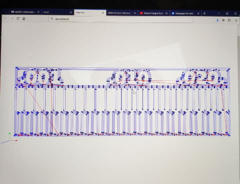
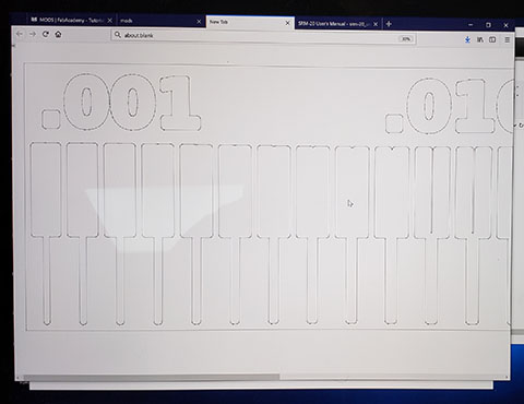
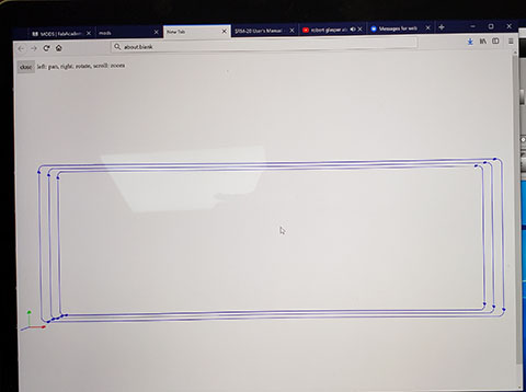
We did this by etching test line widths with different sizes of end mills (0.01”, 1/32” & 1/64”).
See the CAD files and screen images below:
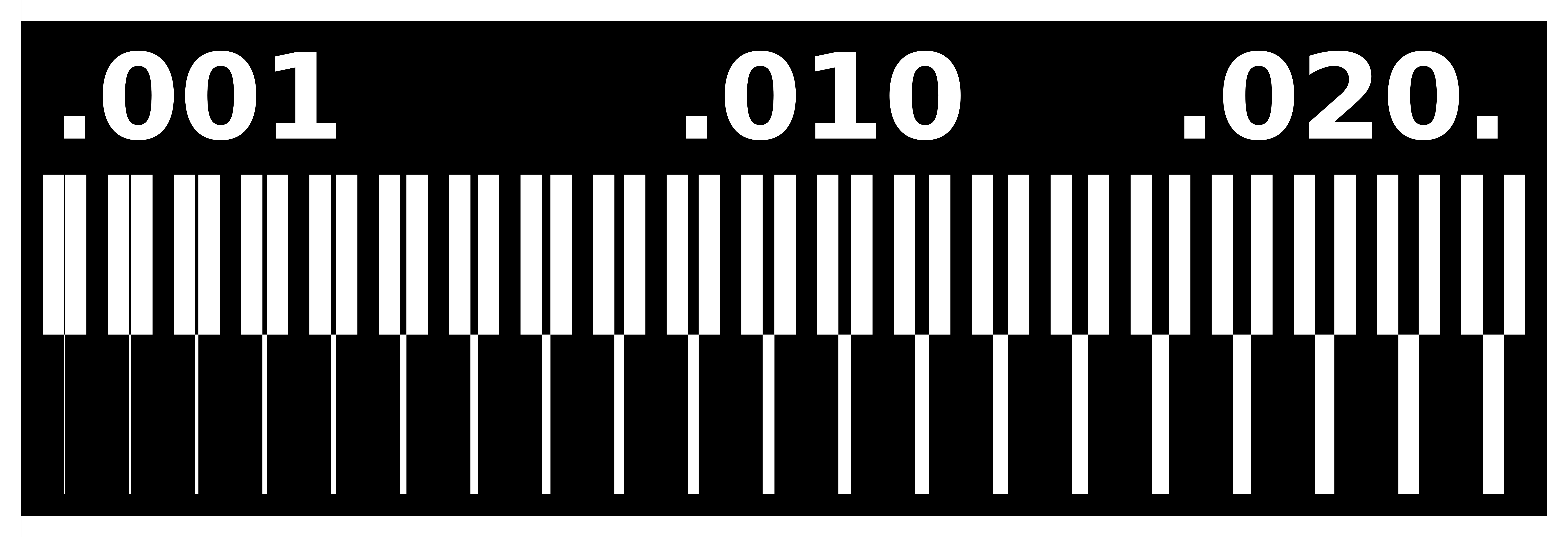

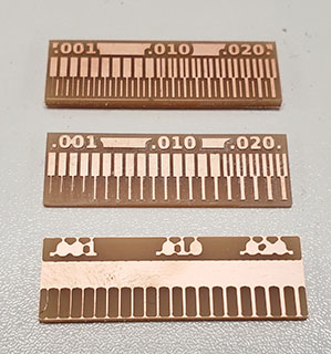
…and here is what the my test characterizations looked like:
Individual assignment
To make my In-Service Programmer (ISP), I used a previous student’s tutorial as my guide, Brian Building the FabTinyISP. The documentation was clear and thorough.
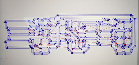
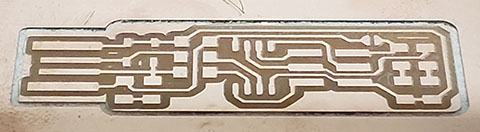
Here are the CAD files and cut file images used to mill my ISP:
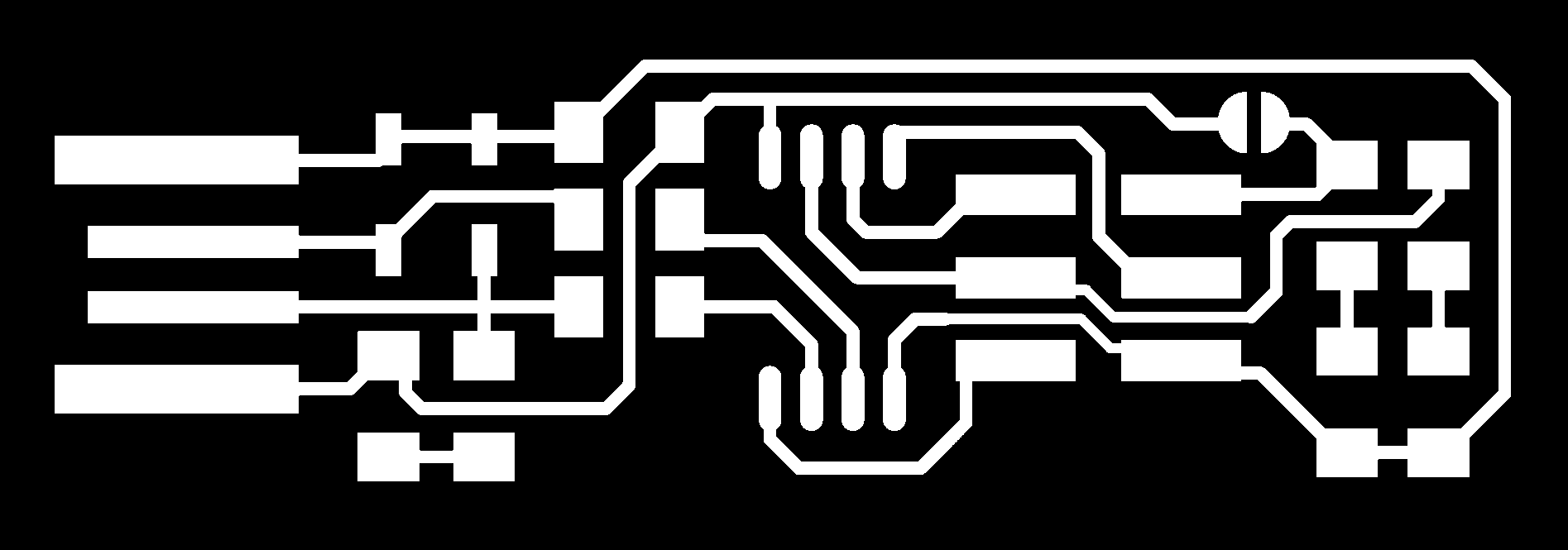

Preparation of the CAD files for milling:
…and here is the finished cut:
The next step was gathering the components for the ISP:
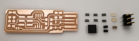
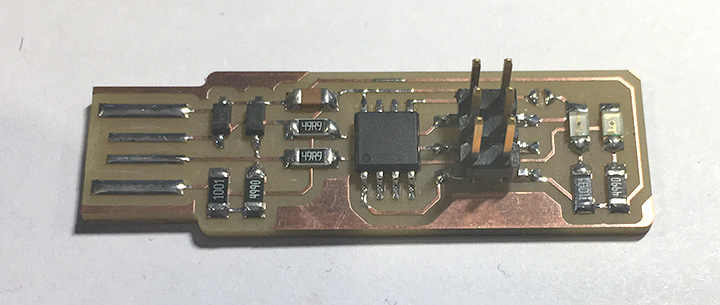
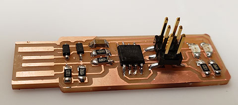
…and then “stuffing” the board (soldering the surface mount devices (“SMD”)) with the following components:
1x ATtiny45 2x 1kΩ resistors 2x 499Ω resistors 2x 49Ω resistors 2x 3.3v zener diodes 1x red LED 1x green LED 1x 100nF capacitor 1x 2x3 pin header
Here is what the stuffed board looks like:
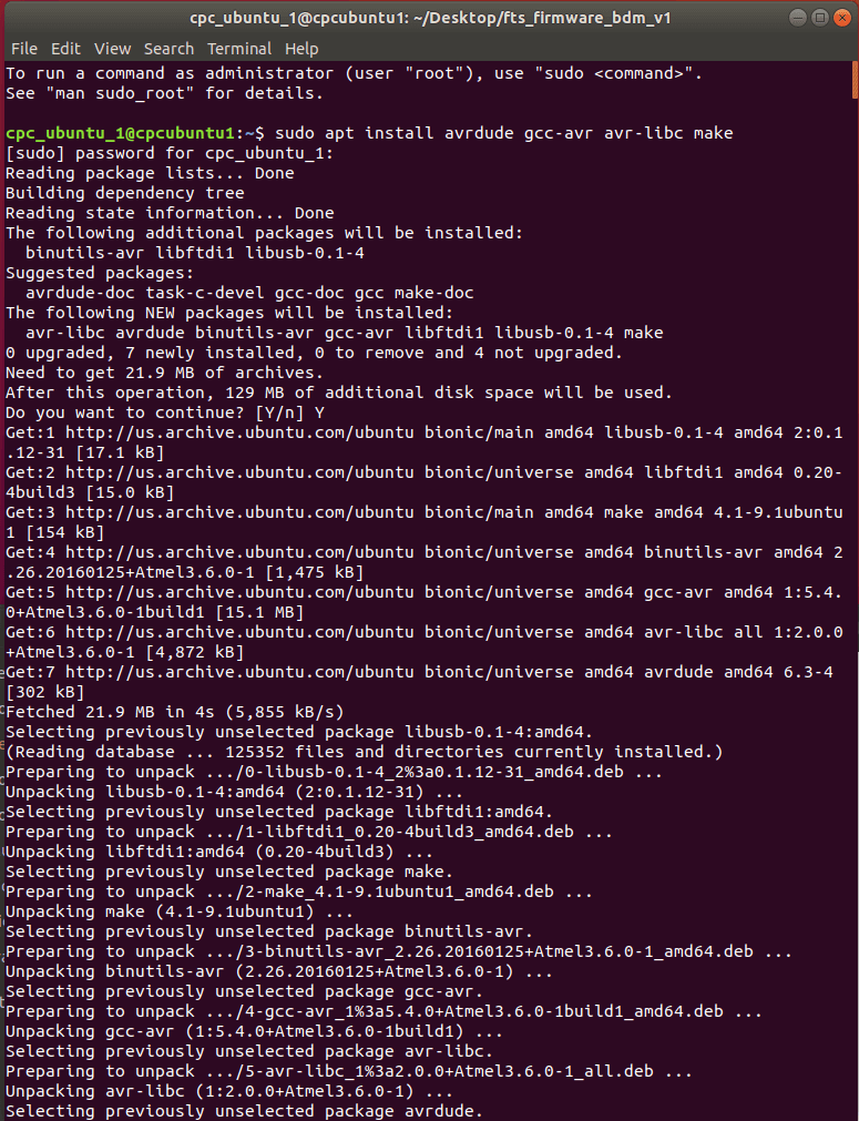
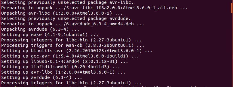
With a fully stuffed board, I proceeded to test the connections of the SMDs to the electrical traces with a multimeter. I verified the conductivity of the traces and then proceeded to the software installation. The first step was setting up the development environment on my computer. I had trouble installing crosspack in the MacOS environment, so I switched to the Linux Ubuntu OS on my laptop. I used the following command to install “avr dude” and it’s libraries:
- sudo apt install avrdude gcc-avr avr-libc make
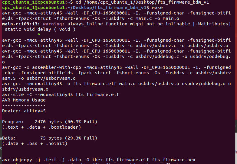
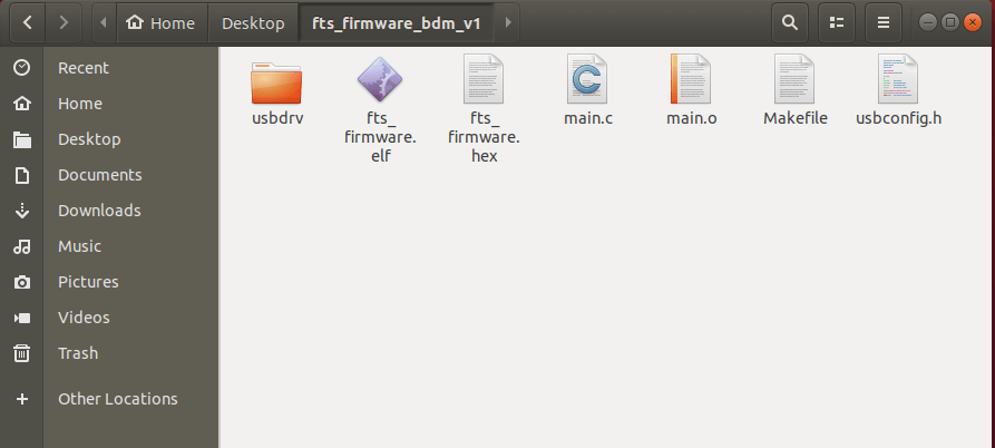
I then downloaded the firmware (fts_firmware_bdm_v1), and then created the necessary Hex file I ran the “make” command. That created the necessary files to install this software onto the ATtiny45 microcontroller on my PCB:
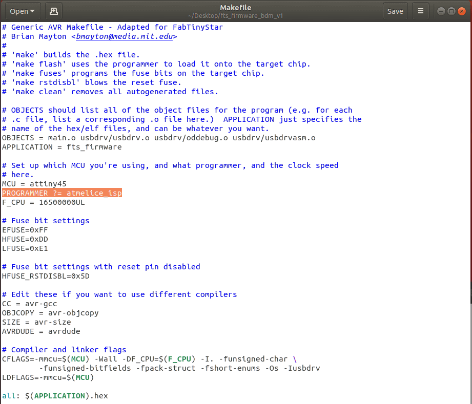
I then updated the makefile to help the computer identify the programming device I used (Atmel ICE):
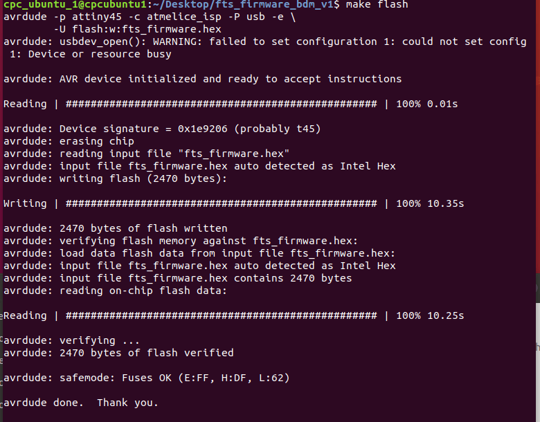
After saving the updated file, I connected the Atmel ICE controller to my laptop and to the PCB I stuffed to install the software. Then I flashed the ATtiny45 with the “make flash” command:
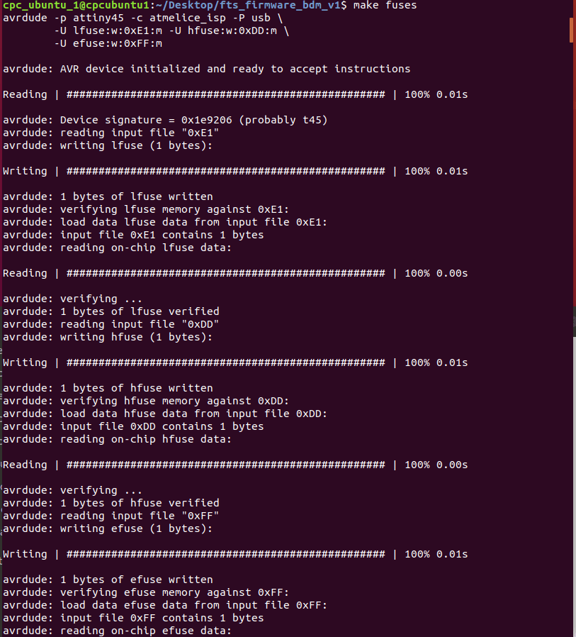
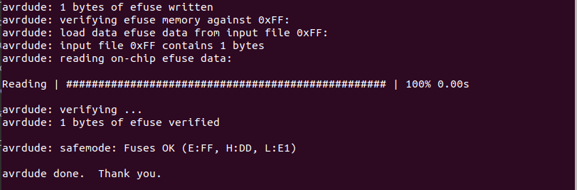
With the PCB flashed I set up and configured the fuses on the PCB:
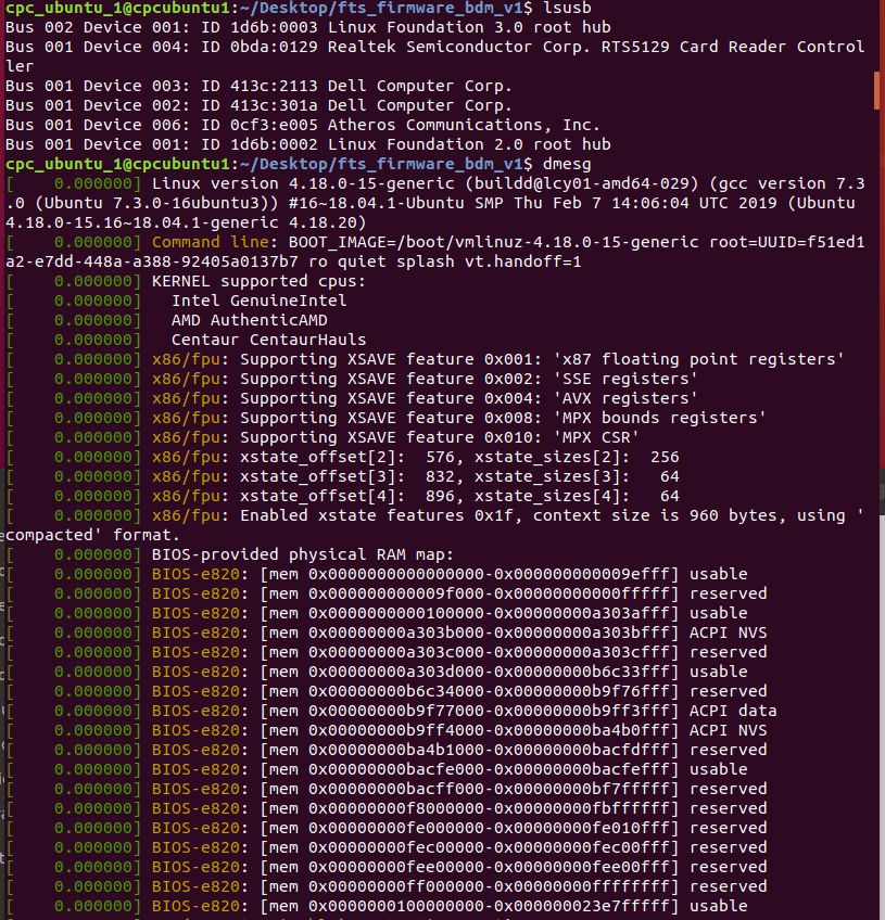
Then I tested the USB functionality using the “lsusb” command:
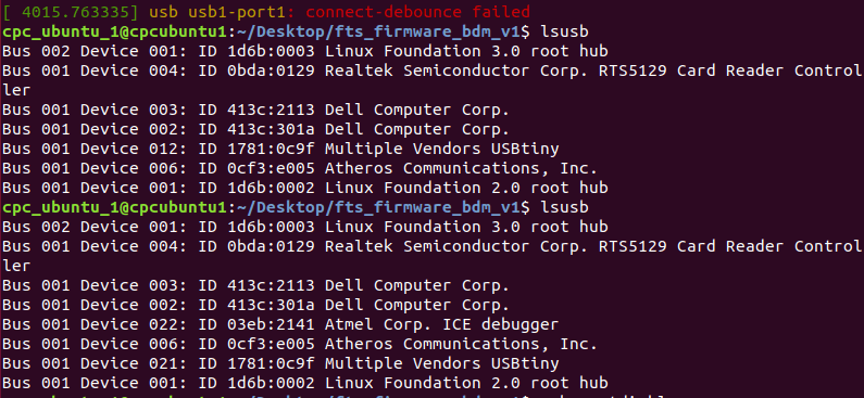
My initial test failed, but I was able to get the PCB to function on the second test (not shown in an image). I then converted the reset pin on ATtiny45 to a GPIO pin with the “make rstdisbl” command, which disables the PCB’s ability to be reprogrammed going forward.
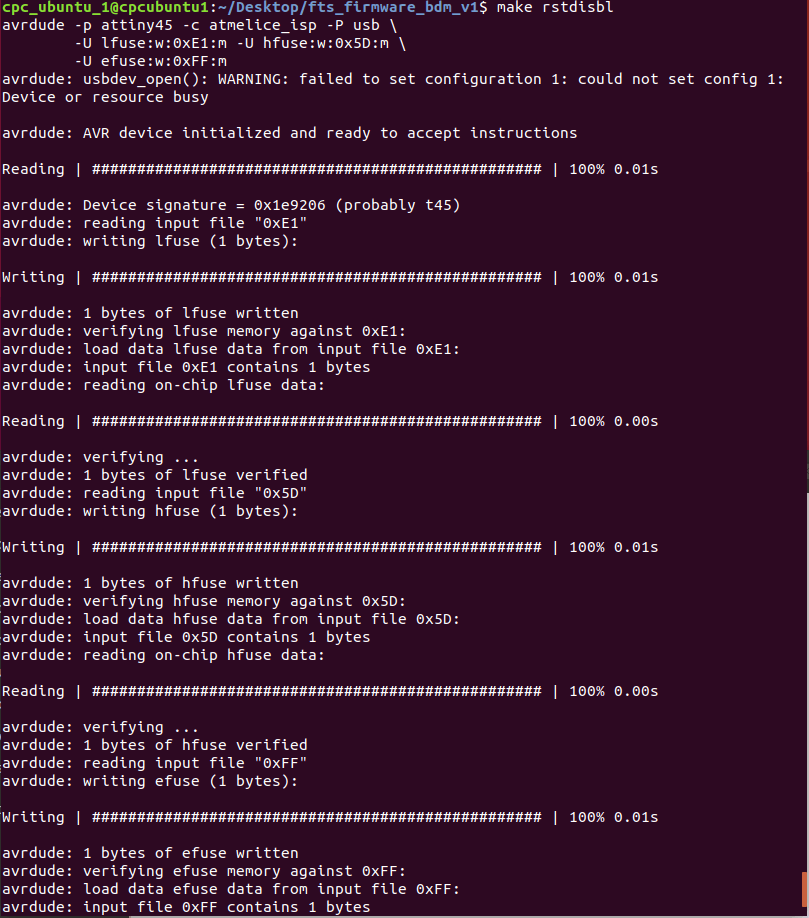
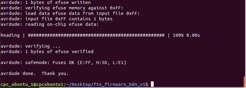
Lastly, I disconnected the Vcc from Vprog by removing the bridge from the solder jumper. Finished ISP Programmer!!!