12. Output devices
Group assignment
Measure the power consumption of an output device
Individual assignment
Add an output device to a microcontroller board you’ve designed and program it to do something
Research
For my individual assignment I’ve chosen to emulate Neil’s DC Motor microcontroller board.
Components
- ATtiny44A (microcontroller)
- ISP 2x2 PinHeader (x2)
- ISP 2x3 PinHeader
- 1uF Capacitor (x2)
- 10uF Capacitor
- Regulator
- 10k Resistor
Pre-Fabrication
Neil’s board and trace image:
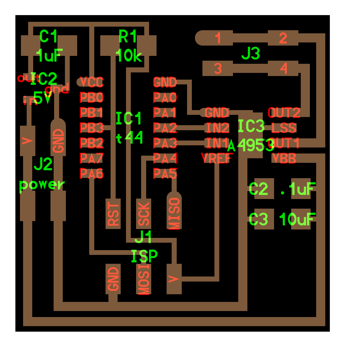
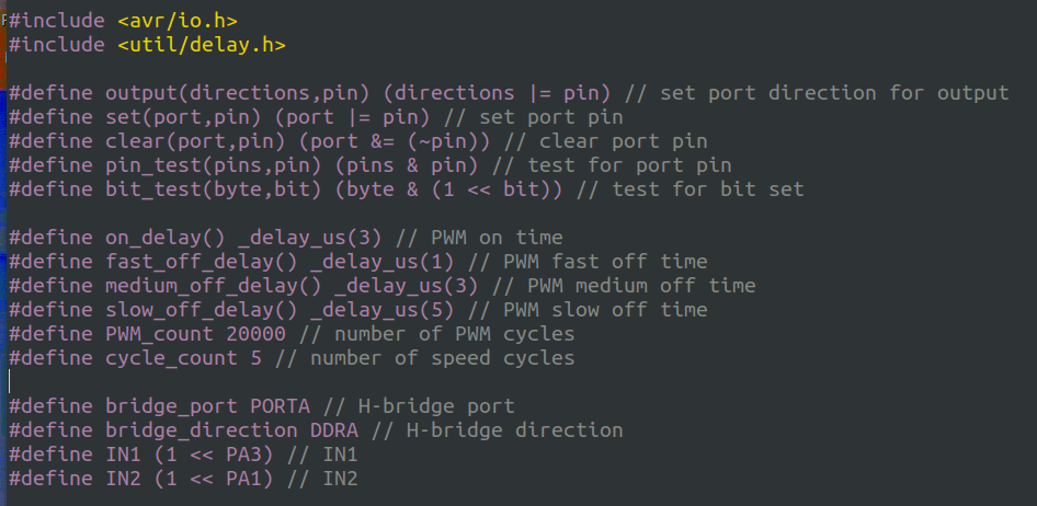
I’m going to emulate this design, including the “h-bridge” (add reference and explanation) for my output device. I’m moving the IN2 connector pin on the Regulator from pin PA2 to PA1. Those 2 pins on the ATtiny44A serve the same function.
Here is the schematic image with the change to the connections:
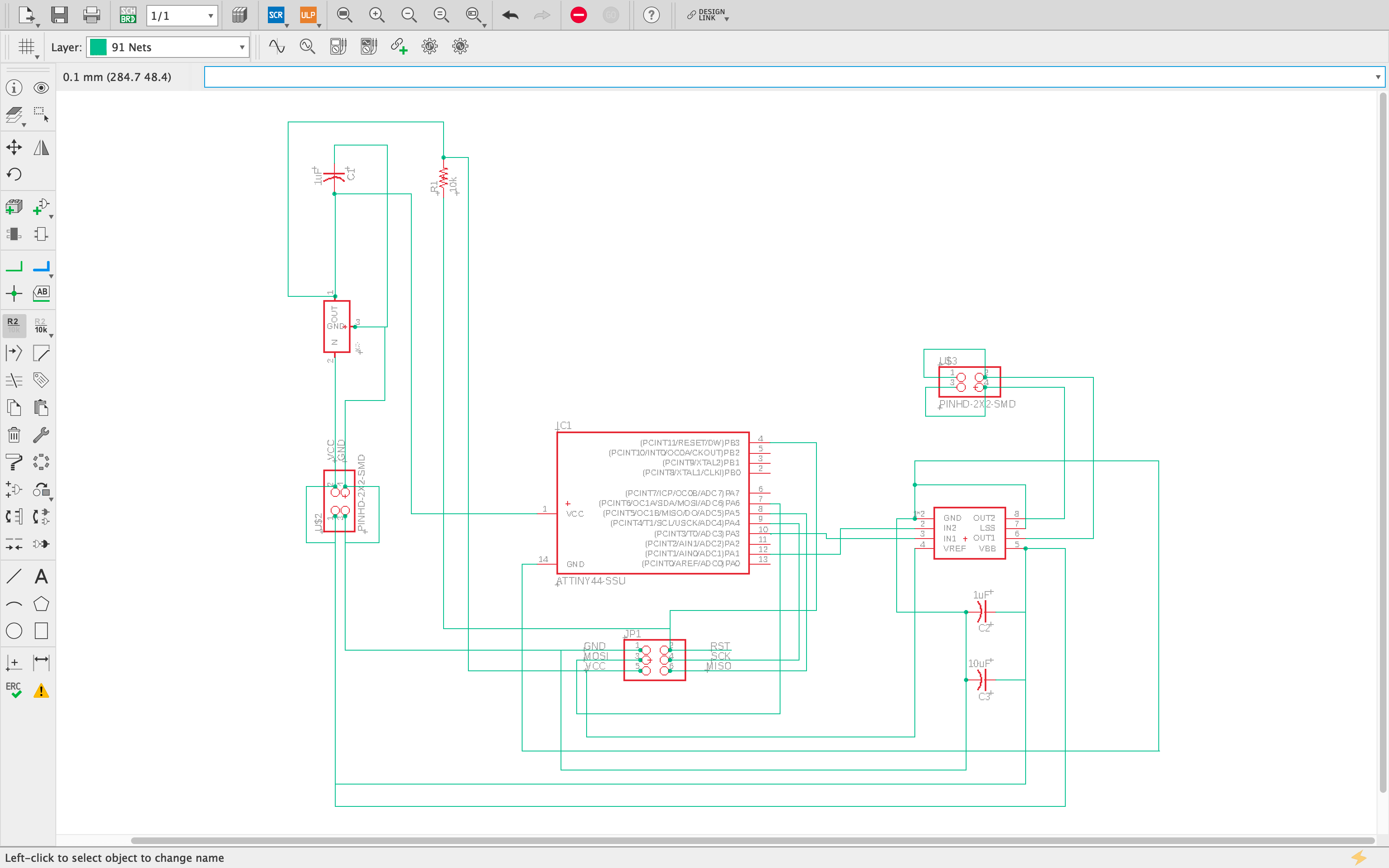
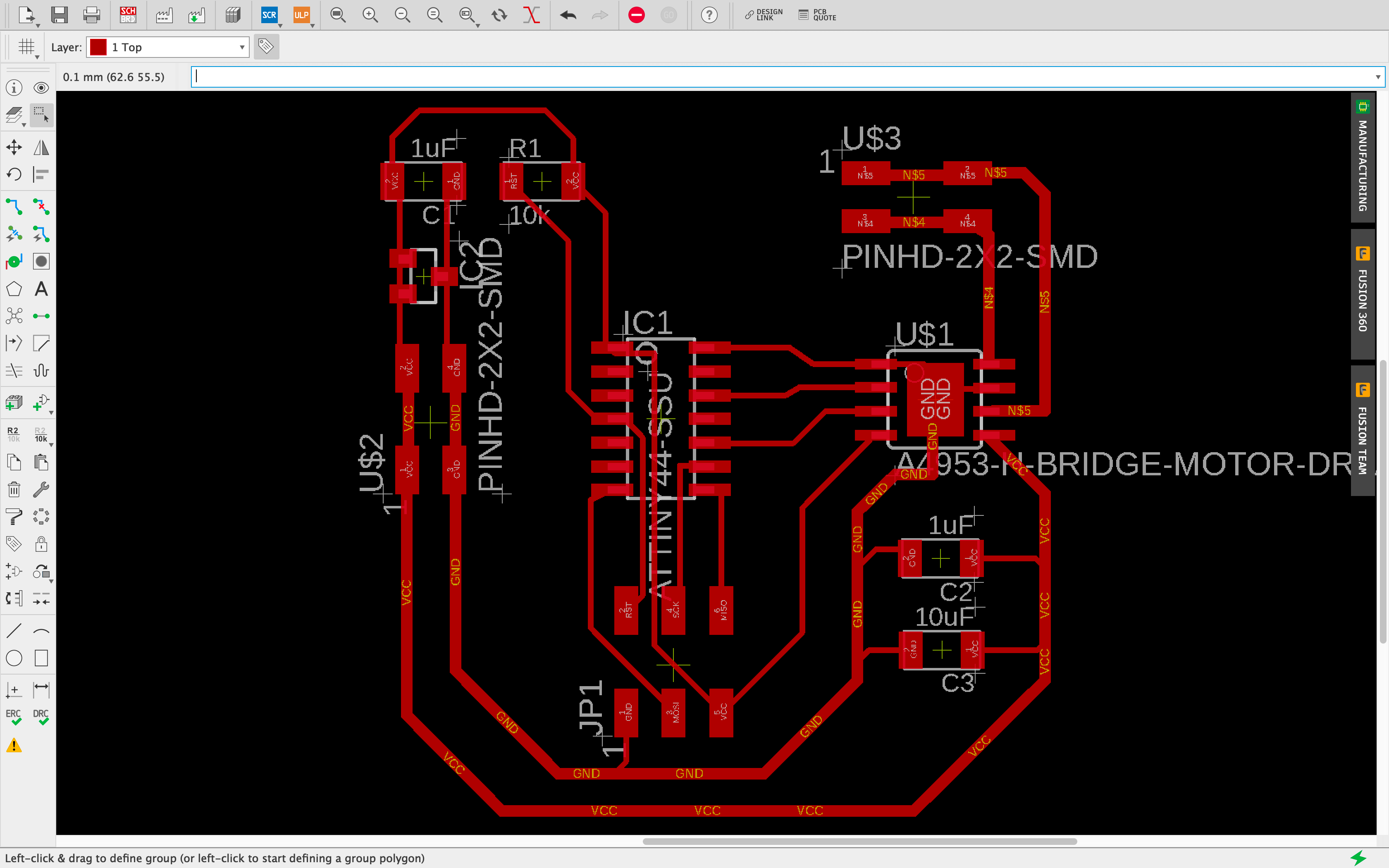
Of key importance to this board design is the thickness of the traces on the fabricated board. Neil informed me that my traces in Eagle (from the previous weeks: Input Devices) were too thin, and suggested I change my standard trace width. Additionally, to handle the necessary voltage, some of the traces need to be thicker this week to accomodate the functioning of the “h-bridge” on this week’s board design (see image of Neil’s board above). I’m going to change my standard trace thickness in AutoDesk Eagle now.
I wasn’t able to find where to universally change the thickness of the routes/traces in Eagle. I auto-routed the board once the components were in place, then I manually edited each trace to change the thickness (0.3048-regular traces, 0.6096-larger traces). That was achieved by right-clicking on each trace, selecting “properties”, then increasing the trace width. See below:
Fabrication
I created the PNG images for the traces and background of the microcontroller in Adobe Photoshop. The board, traces and background were created at 1000 dpi, in preparation for use in Mods, at 2000dpi to achieve the correct real-world size. The board as designed above had to be modified because a few of the traces were not differentiated from the pads in the milling path produced by Mods. In particular, the traces passing through the middle of the ATtiny44A had to be made thinner to enable separation between traces and pads. The final image is shown below:
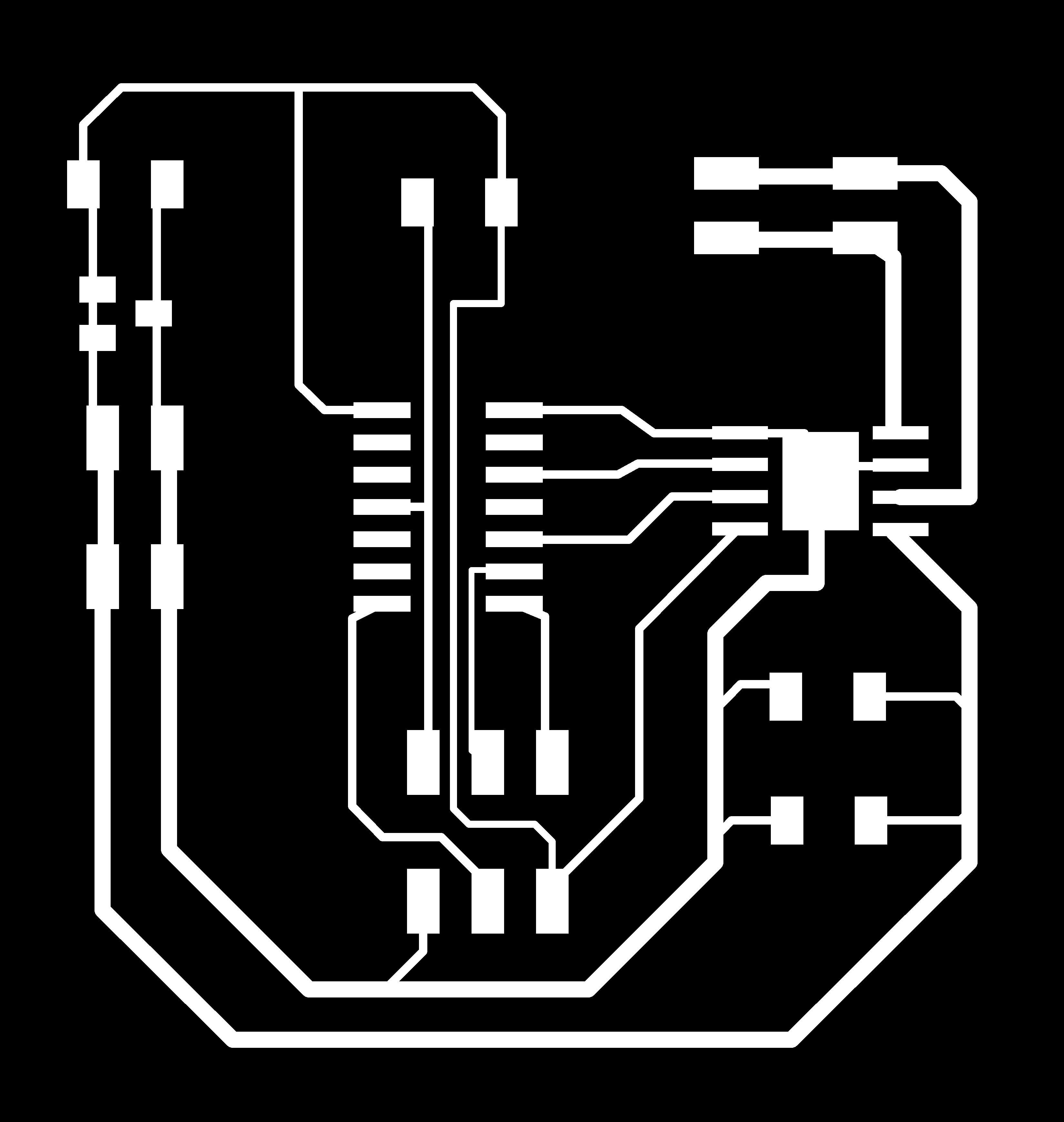

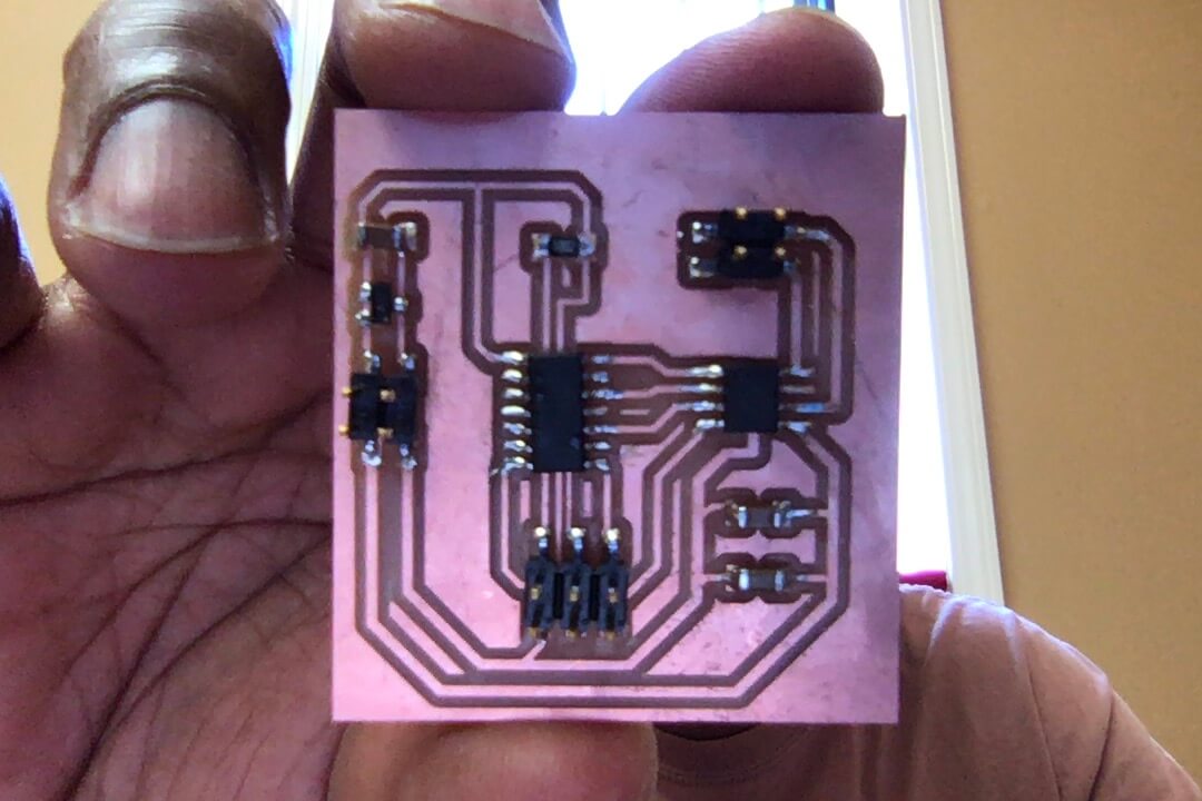
I used the images above to mill the board on our Roland SRM-20 Precision End Mill, and then I “stuffed” the board with the components listed above:
Programming
Equipment
- Atmel-ICE Basic
- Stuffed Output Device
- GW Instek DC Power Supply (GPD-3303D)
- jumper wire (4 lines)
- Connector Socket IDC 4Position (x2)
- Multimeter
Software Installation
I used Ubuntu (Parallels), since it is a stable programming environment. I used the command shell (Terminal) for programming. I first entered the command “sudo” to ensure that I am working as an “administrator”. The necessary firmware to use Atmel-ICE (AVR Dude) has been previously installed on my laptop (see Electronics Production), including the “hex” file needed to flash my ATtiny44.
I edited the makefile, changing the “MCU” to “t44”, and the “PROGRAMMER ?” to “atmelice_isp”, then saved.
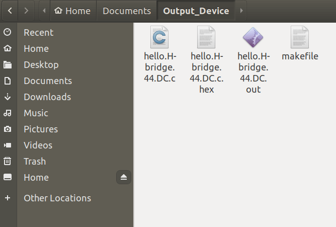
I pointed the terminal to the correct directory using the command “cd” (cd ../home/parallels/Documents/Output_Device) and ran the “make” command to create the necessary “hex” and “out” files needed to flash the ATtiny44 microcontroller.
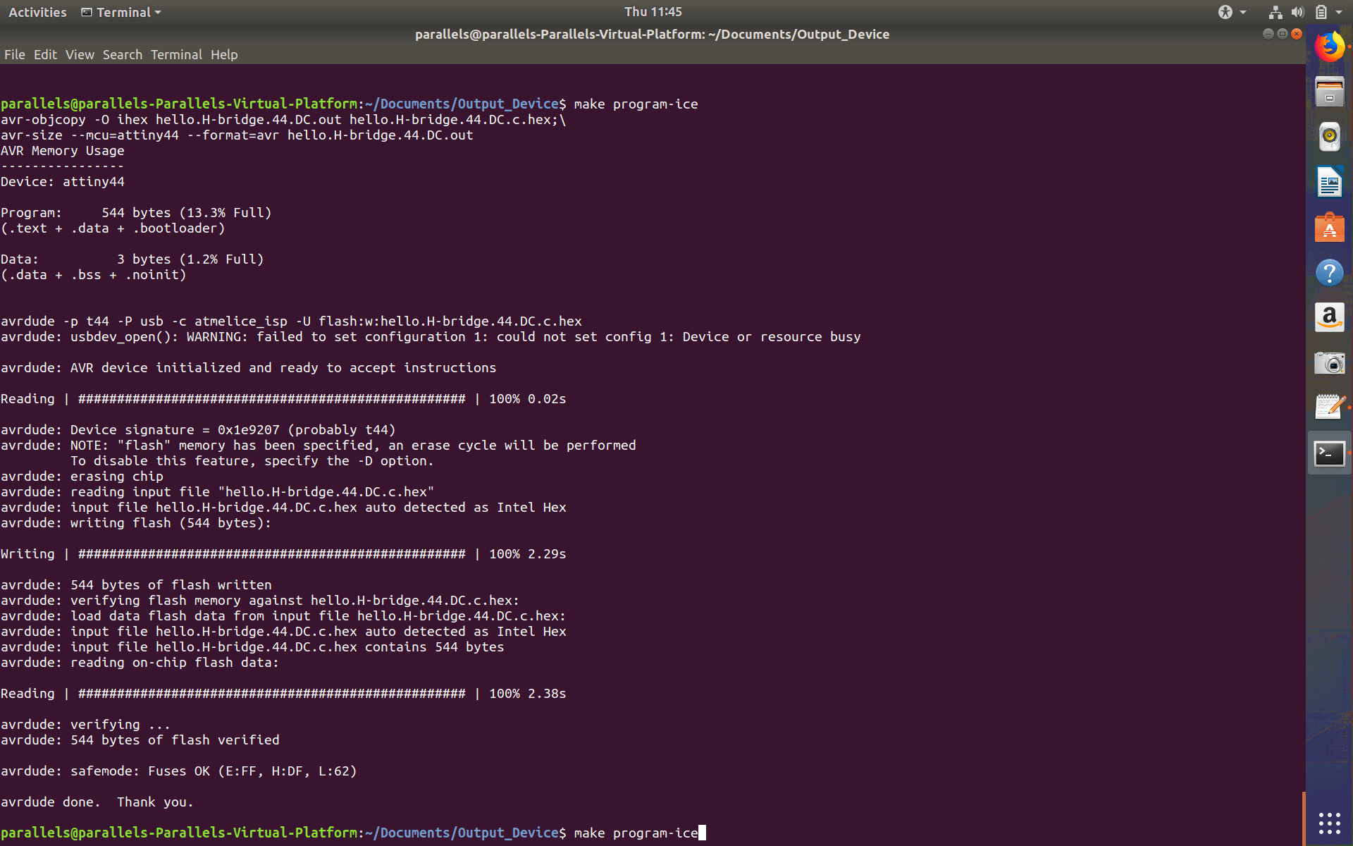
I changed the pin definition within the C program for the DC Motor to reflect the pin change I made to the original design, and then entered the command “make program-ice” and the microcontroller was successfully flashed:
Errors & Lessons
While the programming was successful, it is important to document my mistakes and lessons up to this point.
Unnecessary Programming: Before I discerned what was actually necessary to get this PCB working as intended, I made several errors. (1) Following the same documentation I used to program my first PCB (the FabISP), I erroneously re-downloaded the firmware for the AVR ISP programmer. Also, I erroneously updated the makefile for the FabISP, then flashed my PCB with that program, instead of using the correct makefile and program for the DC Motor application. I was on auto-pilot, lol. Having recognized my error after the fact, and being reminded (thankfully) that the ATtiny44 can be flashed thousands of times before expected failure, I moved on to flashing the microcontroller with the correct programming. (2) My first programming effort failed, despite the fact that I saw that the PCB could be flashed/programmed. My mistake was commenting out all of the other programmers in the makefile before using the “make” command. I thought this was necessary for the program to isolate the device that I was using to flash my microcontroller. After being stuck for a while, Blair (Node Instructor with Incite Focus) showed me that the makefile checks for what device you’re using and only executes the code needed using that device. (3) Lastly, I was unclear what the programming work-flow was between the makefile and the C program I intended to use. Was it necessary to compile the hex and output files first, before running the C code? Could one command have the makefile compile the hex and out files AND activate the C program? With Blair’s help, I was informed that either way was possible. Since I learned that the makefile could be compiled before the C program was run, I chose to move forward with that workflow (as seen above). (4) Even after I successfully flashed my Output Device board with the correct C code, the motor did not initially move. The board was connected to the external power supply at 5 Volts and 0.1 Amps. It wasn’t until I turned up the Voltage to around 7 Volts that the motor began to move. The key here is that the “H-Bridge” design of my board requires a higher voltage than is needed for the operation of the ATtiny44, which is designed to operate at 12V, with regulator stepping down the voltage coming from power (VCC) to the microcontroller. At 12V the motor ran smoothly without shutting down, or the power supply attempting to increase the amperage to compensate for insufficient voltage. Basic function demonstrated below: