Week07: Electronics design
Individual assignment
- Redraw the echo hello-world board, add (at least) a button and LED (with current-limiting resistor), check the design rules, make it, test it.
Research
I started by rewatching Prof. Gershenfeld’s lecture for this week. To begin with I feel pretty lost, but I am working to identify the necessary components that I will be using to redraw the “echo hello-world” board, and then watch tutorials to help me with design software. I originally intended to use KiCad as my design software, but decided to go with AutoDesk Eagle, since I am more familiar with AutoDesk software.
I figure visual representations will help me get a grip on what to do for this assignment:
Tutorials
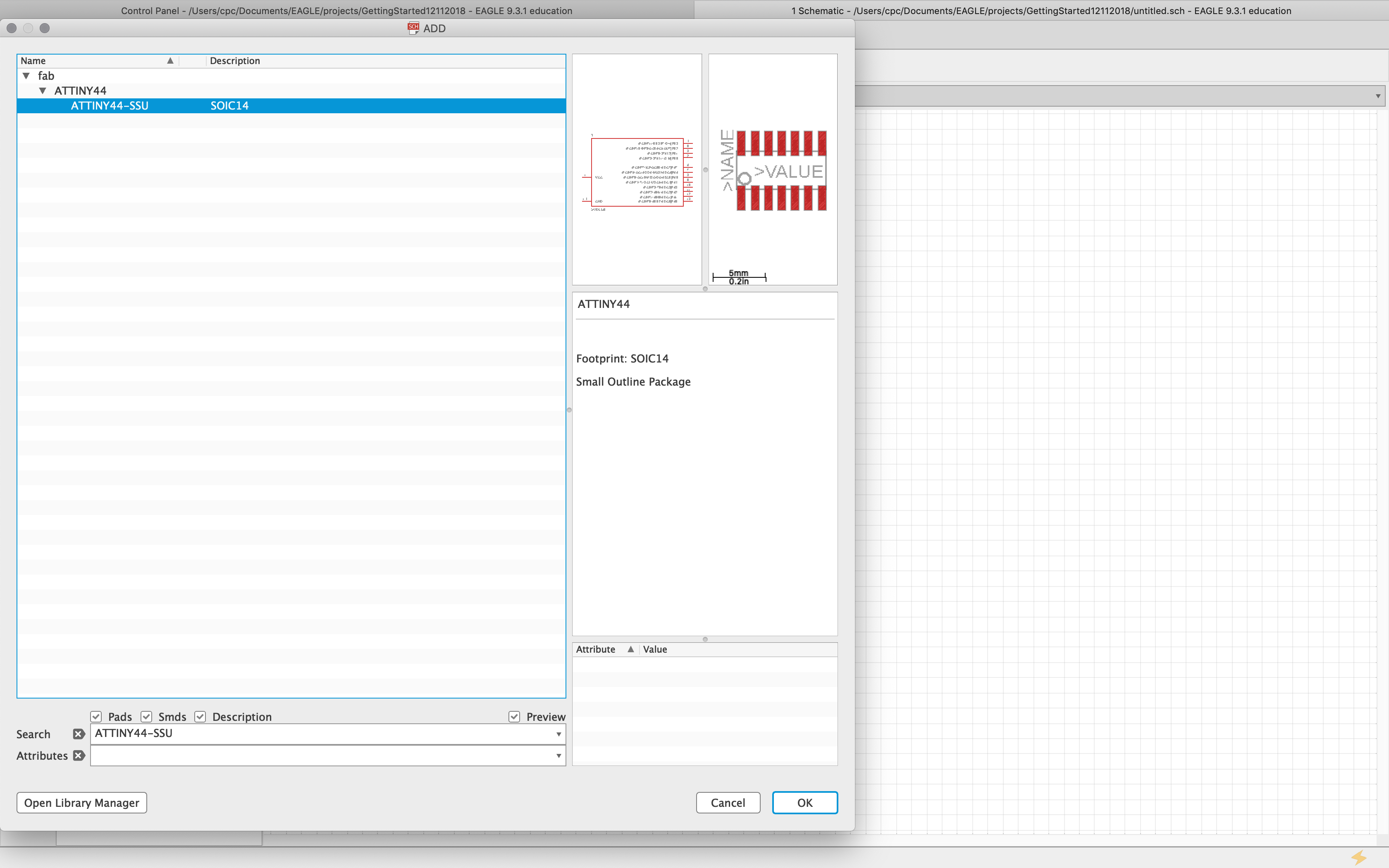
So, I tried building my board while going through this tutorial, but right away I had trouble trying to find the ATtiny44 in the parts libray of Eagle. My first Google search yielded no results. After several attempts to find the ATtiny44 via Google search, I entered “how to add attiny44 to autodesk eagle” and found this link to Bob Wu’s Fab Academy page for Electronics Design, which had the ATtiny44 in the fab library for the Electronics Design components. After uploading the fab library to the application folder for Eagle on my Mac, I used the search term “ATTINY44-SSU”, which directed me to the ATtiny44, now in my Eagle library.
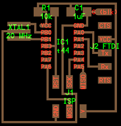
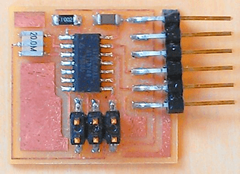
I realized next that I, at least, need to identify all of the components used on the “hell-world” board, so that I can place them in Eagle as I’m going through this tutorial. I used the physical image, along with the diagram, of the “hello-world” board above to help me identify the necessary parts.
Components
- IC1 t44: 1x ATtiny44
- J1 ISP: 1x (2x3) pin header
- J2 FTDI: 1x (1X6) pin header
- R1: 1x 10k Ohm resistor (1002)
- C1: 1x 1microFarad (1uF) capacitor
- XTAL1: 1x 20MHz Resonator (20.0M)
I’ll take these as the basic components of my board, and add what is necessary to the list and design once I get to that point. I don’t know how I would find the necessary parts in the library without Bob Wu’s Fab Academy documentation. Thankfully, he provided search methods and search terms for each item.
Designing the Board
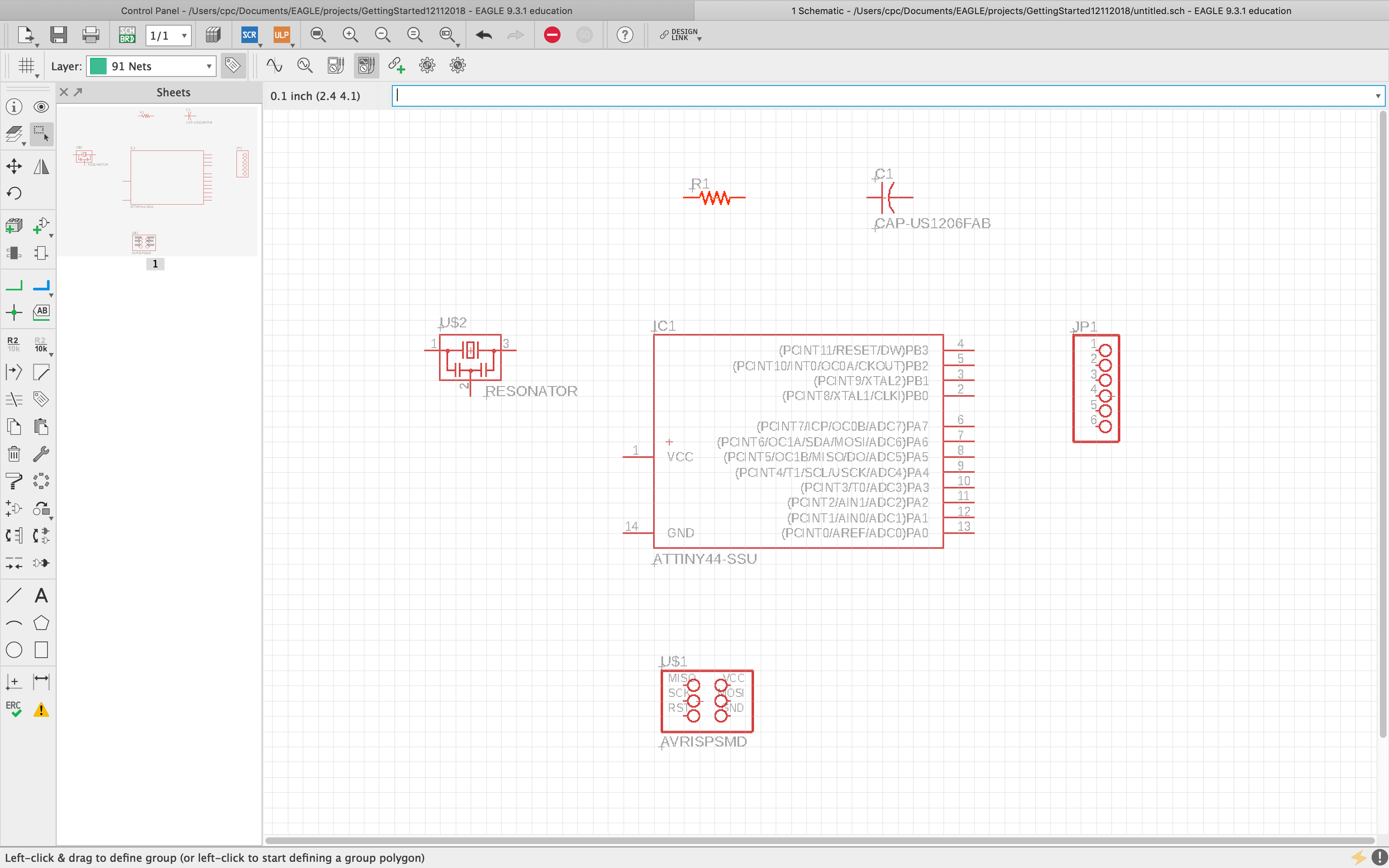
I placed the basic components in Eagle:
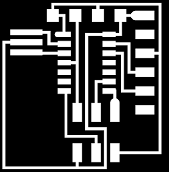
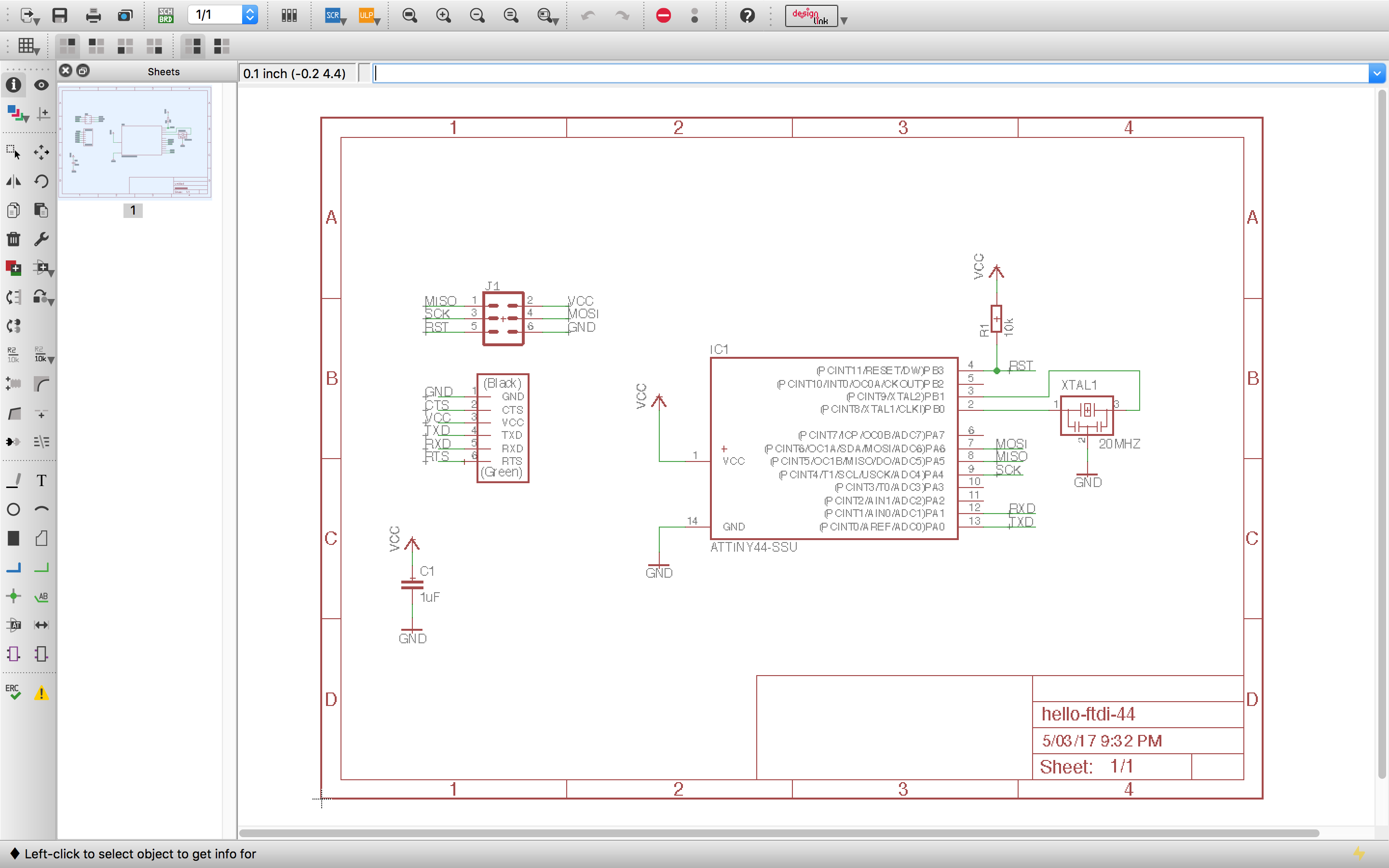
I remembered to visit the Fab Academy Tutorials for this week. There is supposed to be a downloadable sample schematic: hello.fdti.44 schematic, which links you a page of code, but nothing downloads, as per the tutorial. The link is also mislabeled “fdti”, instead of “ftdi”. Nevertheless, I just downloaded the schematic image from the tutorial page:
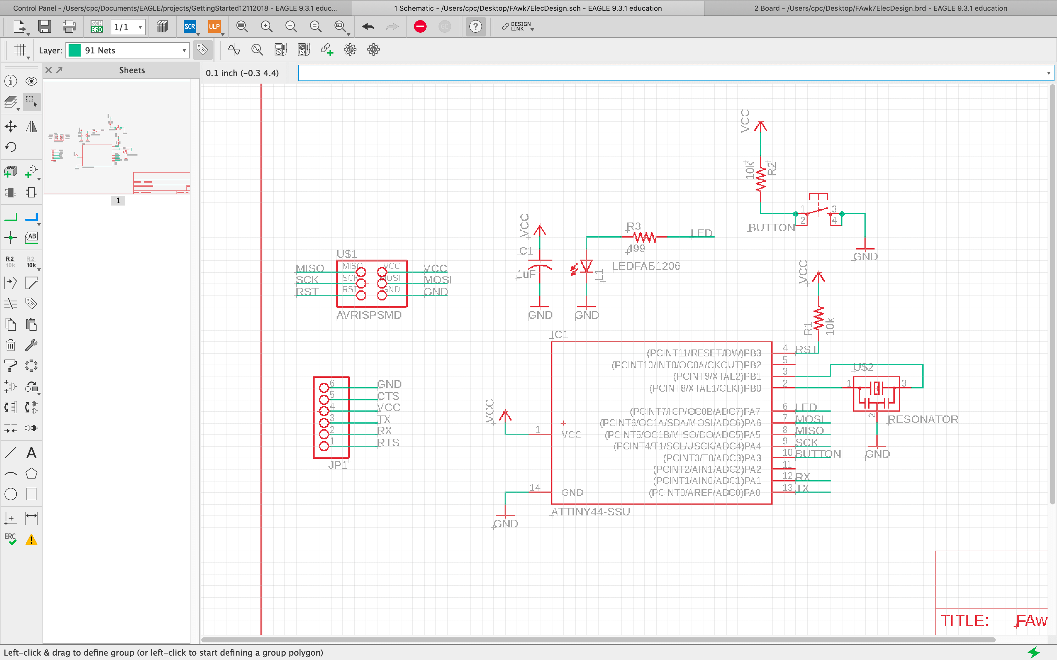
Using that schematic as a reference helped tremendously. I was able to create my own:
I spent most of the day trying to create my traces on board only to find out that the 10-pin on the ATtiny44 was NOT connected to the button. I tried fix it, then lost connection between my schematic and my board in Eagle. I ended up deleting the project and starting over :(.
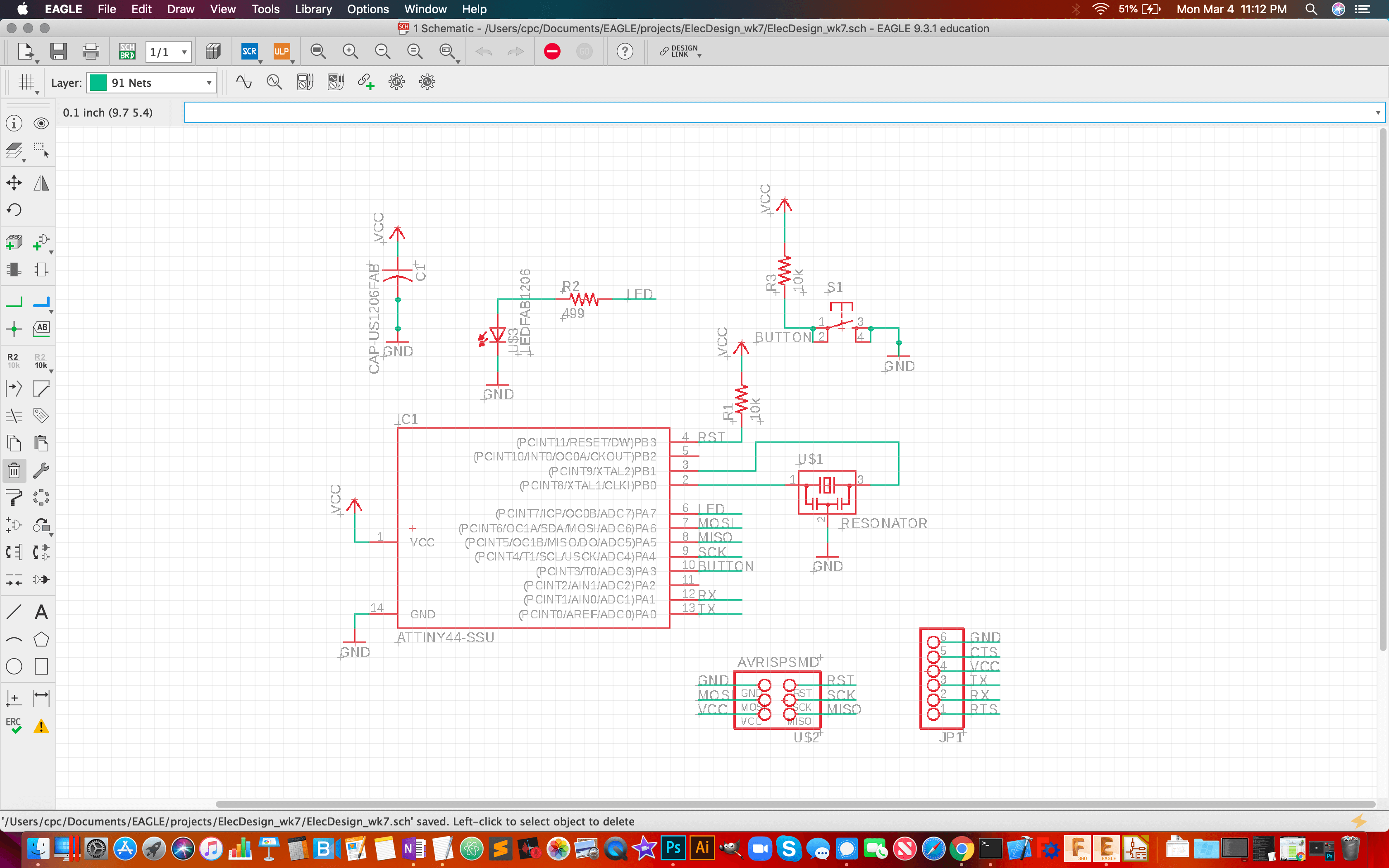
I started from scratch and was able to create a schematic and a board:
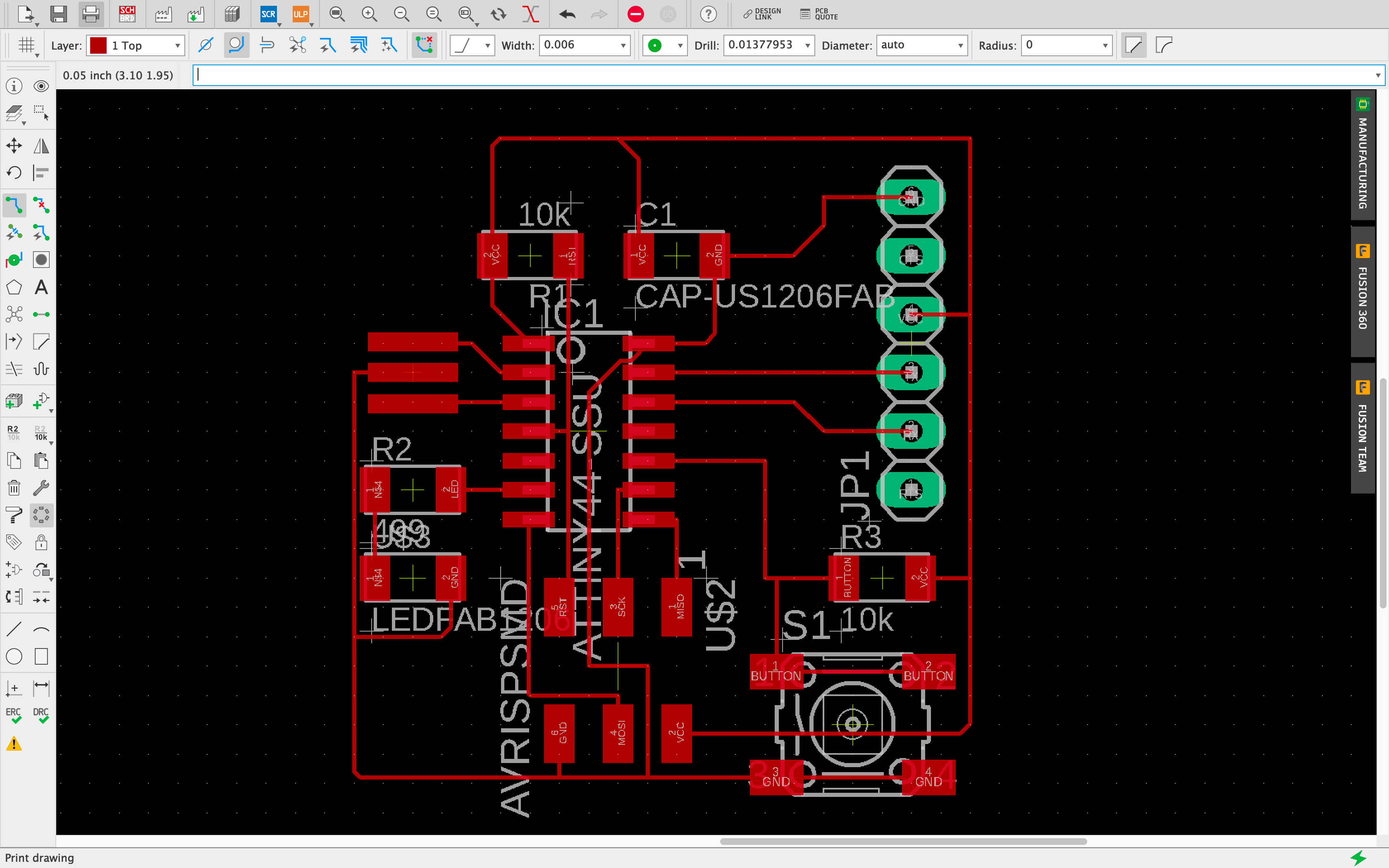
Design Rules Check (DRC)
I had many errors when I ran my DRC (over 60). Most of them were traces (nets) that were too close to the components. The big lesson, however, was that I needed to increase the width of my traces. I wasn’t able to find a single operation that allowed me to correct this for all traces at once, so I manually increased their width from 0.006” to 0.01”.
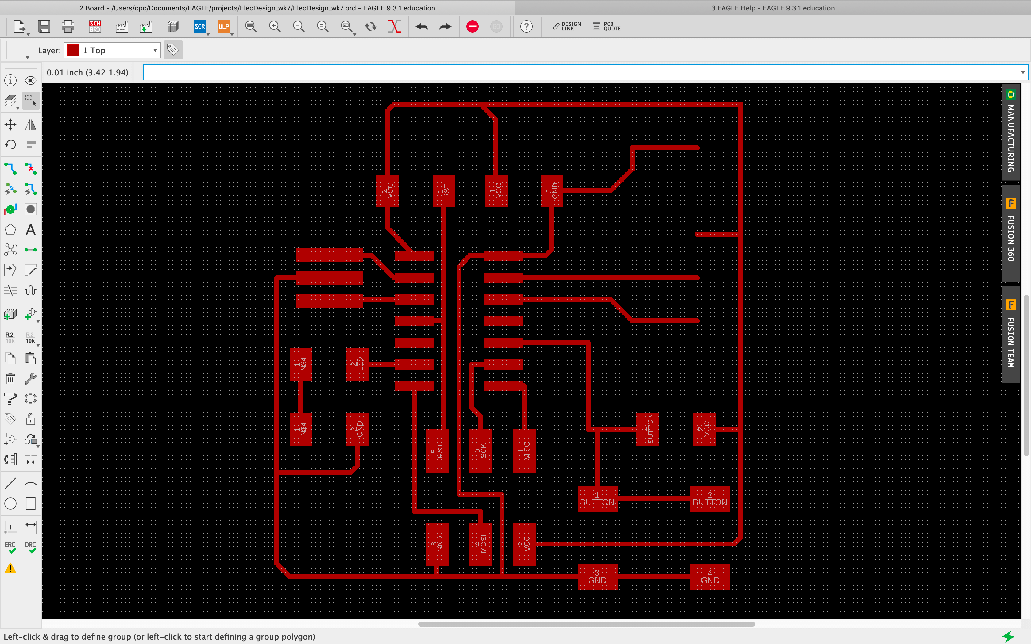
With the Board designed, it was time to prep the image for fabrication.
Fabrication Prep
The first step was removing extraneous layers in my board image (i.e., removing the components and text from the image, leaving only traces and pads).
This is where things began to go wrong, with time running out. I didn’t notice a few crucial problems: 1) the pads for the (JP1) 1x6 Pin Header are missing, and 2) I didn’t realize that this image was not scaled properly before rushing off to fabricate my traces on the Roland SRM-20.
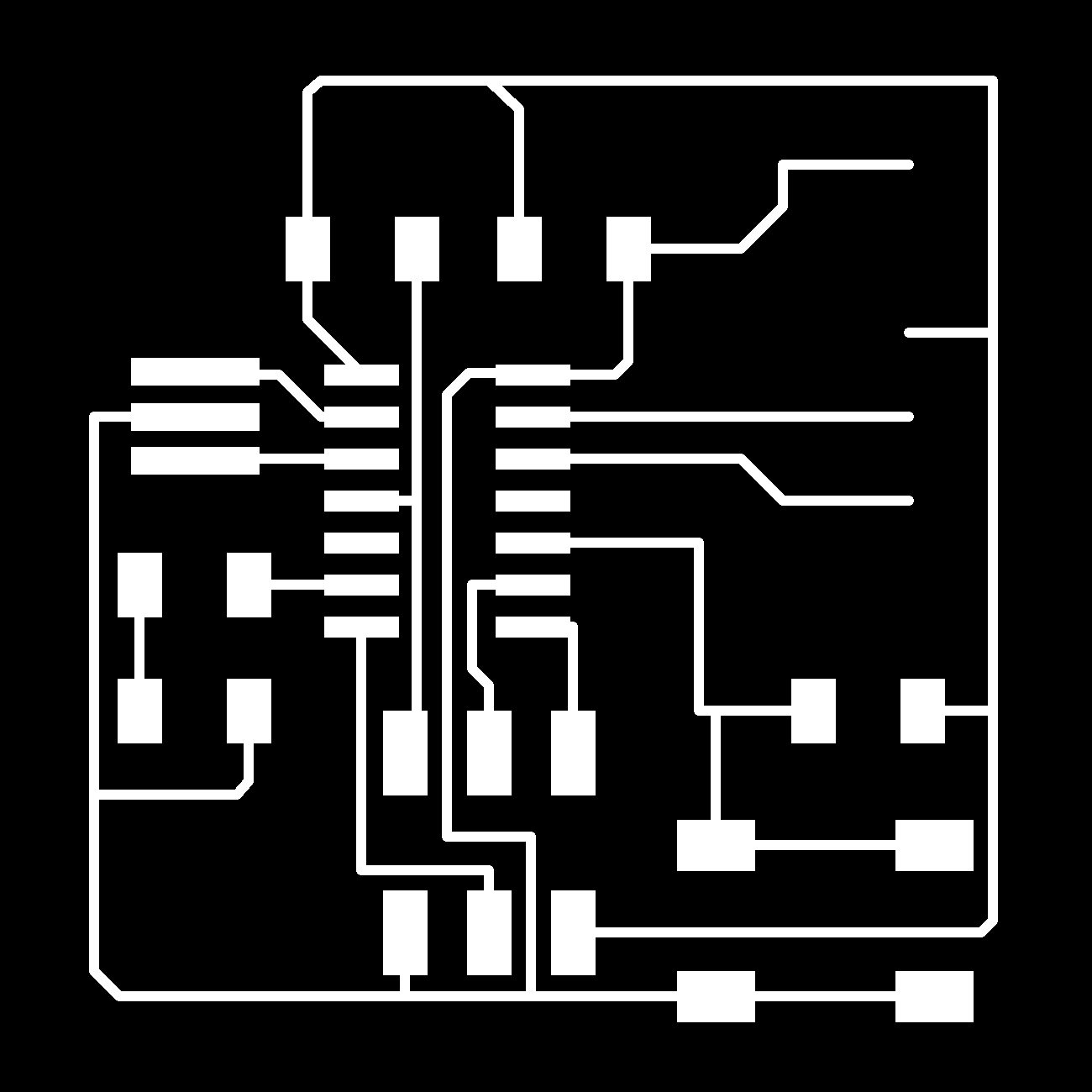
I rushed to cut the traces before it dawned on me that my components wouldn’t fit on a 2.7”x2.7” PCB.
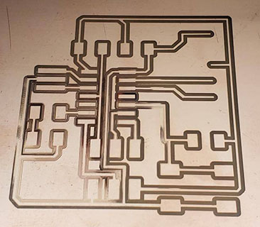
At that moment, I remembered that the tutorial warned me about that, so I began to search for a solution. Nothing in any of the documentation (for working in Eagle) suggested I could resize the board image to match the size of the components. Nor did any Google search I could think of provide any definitive answer. The closest I got was using Eagle to produce a Gerber file, which I did. Once I did, however, I wasn’t able to find a way to set up the file for conversion to a png, or anything else usable. I’m stuck for the moment.
After consulting with my node lab, Incite Focus, I will try to export my board image from Eagle again. This time at 1000dpi, instead of 500dpi.
Backtracking and adjustment
In consulting with my node advisor, Blair Evans, I was informed that my board could be more efficiently designed if I removed the resistor between my button and VCC. I had such difficulty creating the traces on my board, prior to making this adjustment, but once I did, creating the traces was ridiculously simple. Thanks Blair!
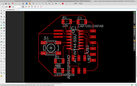
Updated Components
- IC1 t44: 1x ATtiny44
- AVRISPSMD: 1x (2x3) pin header
- FTDI-SMD-HEADER: 1x (1X6) pin header
- 6MM_SWITCH: 1x Button
- US1206FAB: 1x Capacitor
- LEDFAB1206: 1x LED
- RES-US1206FAB: 1x 10k Ohm resistor
- RES-US1206FAB: 1x 499 Ohm resistor
- C1: 1x 1microFarad (1uF) capacitor
- XTAL1: 1x 20MHz Resonator (20.0M)
Frustration
So, after many, many attempts to produce a usable image for milling this pcb using Eagle, I am going to try this process in KiCad. Every tutorial, web search and question I asked my node resulted in extremely frustrating dead ends. I haven’t found a way to verify that the board image that I produce is the correct size for milling. I couldn’t figure out how to resize the board in Eagle. The images that I produced were far too large, and I wasn’t convinced that the dpi manipulation that I was doing in Mods was going to produce the right size.
Switching to KiCad
I searched for a tutorial to get me started using KiCad, hoping for better end results.