Final Project - The Makeswaves Machine
Final Reflection
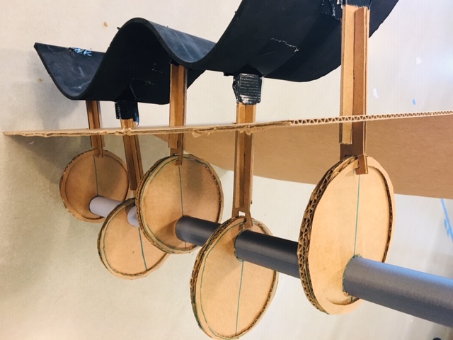
I was very happy with the finished product, although there’s much I still wish to do. What works quite well is the structural design constraining the motion of the pistons. It’s fun to look back at the original cardboard prototype and see the initial idea get started - see below the cardboard prototype - and see how far it’s come along. One of the pistons is still misfiring it seems - it keeps getting caught up on the wheel. The laser cutting wood structure turned out nice - I was happy with the material finish…it was a nice plywood we had in stock in the lab. The living hinge surface almost worked, but led to a kinky wave, due the connection with the piston armature. I would like to spend more time on getting the surface to be a smoother waveform. I think if I had a thinner material, 1/16” or less, that was both flexible and not too brittle, it might stand up over time. I also would like to look into a more powerful motor.
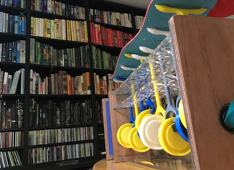
The Makeswaves Machine at home in front of my waveform bookshelf!
Vision
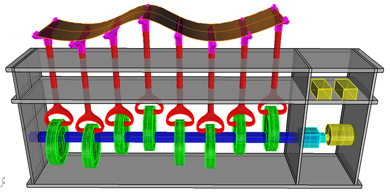
This project is a relaxation device for home bookshelf use that creates a dynamic physical wave form for visual pleasure. It utilizes a camshaft to translate rotation into syncronating up and down linear motion along a single axis. The project idea originated from our group project in which we built a Rube Goldberg Machine. My module was a wave machine that could translate a ball horizontally without a conveyor belt. For the final I have taken that original design and further refined various components including motor control, power management, and structural and mechanical design.
Final Video
Video also available on Fab Academy Final Presentations page
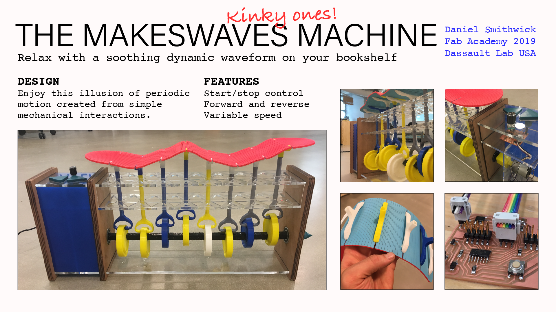
Final Slide

Slide also available on Fab Academy Final Presentation page
Licensing
I will use this license for my project, to allow others to freely download and adapt my design, Creative Commons BY-NC 4.0
Many Thanks!
- The Dassault 3D Experience Lab Team:
- Alex
- Lucas
- Madu
- Abhishek
- Lucas
- Robert
- My Classmates
- Aleza
- Jose
- Alex
- LaShawnda
- Jose
- Our Instructors
- Greg
- Luciano
- Neil
- My colleagues for the Patience!
- Sonya
- Sherry
- Nettrice
- Melvin
- Rebecca
- Simone
Bill of Materials
My slide documents the laser cutting, 3D printing, electronics and embedded programming with input/output control, along with 3D design and modeling.
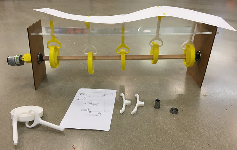
This picture shows all the components of my project:
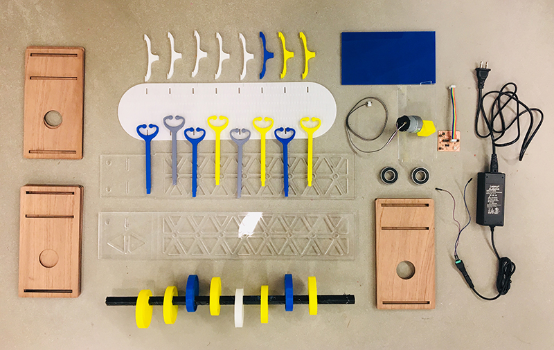
BOM: - Laser cut 1/8” plywood vertical stablizers - Laser cut 1/4” acrylic horizontal stablizers - Laser cut motor mount and containment walls 1/8” acyrlic sheet - Laser cut 1/8” acyrlic living hinge surface (ultimately I cut this out of 1/8” plywood) - 3D printed cams and pistons, mounted to store-bought 1/2”x24” wood rod - 3D printed motor coupler - 3D printed interface buttons (not pictured) - 12V DC Motor - (2) 1.5” ball bearings - Microcontroller board - A4953 H Bridge Motor Control - ATTiny44 MCU - .1uF Capacitor - 1uF Capacitor - 10uF Capacitor - 5v regulator - (2) 10k resistor - Schottky 100v 1A mini Diode - (2) 2x2 header (for power in and for motor out) - (2) 2x3 header (MCU programming and H Bridge Programming) - 2x5 header (for serial control) - AC/DC wall outlet plug
Files for final Project
Final Arduino Code - Motor Control
//code by Daniel Smithwick 2019
//this code is modified from Greg Buckland 2018 Fab Academy
//this one toggles through a preset list of speeds in one direction
//each button press advances through the list:
//[off, fast]

#define in1 6
#define in2 7
#define buttonPin 0
#define off 0
#define slow 100
#define medium 175
#define fast 255

int counter = 0;
int counterMax = 2;
int buttonState = 0;

void setup() {
  pinMode(buttonPin, INPUT);
}

void loop() {
  // put your main code here, to run repeatedly:

  buttonState = digitalRead(buttonPin);   //read the button

  if (buttonState == LOW){    //if button is pressed
    delay(200);     //give user time to press and release button
    if (counter >= counterMax)    //if counterMax is reached
      counter = 0;      // reset counter to 0
    else
      counter++;      //otherwise, increment counter by 1
  }

  switch(counter){
    case 0:
      analogWrite(in1, off);
      analogWrite(in2, off);
      break;
    case 1:
      analogWrite(in1, fast);
      analogWrite(in2, off);
      break;
    default:
      analogWrite(in1, off);
      analogWrite(in2, off);
      counter = 0;
      break;
  }

}
Additional Videos
I was excited to do additional videos to reflect upon the quality of the wave. The slow motion video shows the one piston getting stuck and having to hammer its way up. You can also see all the vibration of the surface. Lastly, as I originally intended, the Makewaves Machine is eventually to be made for people’s bookshelves - a nice soothing - or perhaps just amusing - machine to have on display. You can see my other waves in the bookshelf!
Slow Motion Video:
At home in front of the bookshelf:
Design Iterations
Prototype 3 Test Video
 Prototype 3 Design
 Prototype 2
 Prototype 1
Additional Documentation of Final
- Week 15 Mechanical Design
- Week 17 System Integration
- Week 18 Wildcard Week - CNC Embroidered Surface
Background Research
My initial inspiration was this eccentric cam-mechanism project. I based my eccentric camshaft on this person’s idea, which was to carry a marble up occilating steps.
I did find some related Fab Academy Projects:
Trichitalchen - a biomimetic submersible Pretty cool! The wave form is slightly different from mine - it has more dimensions of movement. Mine seems simpler in this sense.
Electronics Design and Production
Ready, Fire, Aim! Neil said this in lecture this week as a non-inuitive approach to solving problems and making projects. Starting without knowing where it will all go. Learn about the target and it’s location after attempting to fire at it as a secondary action.
I knew I wanted a DC motor controlled with a button that could be programmed to change speeds and directions. I did a lot research looking into other students’ project including:
Here is Neil’s original H-Bridge design: http://academy.cba.mit.edu/classes/output_devices/H-bridge/hello.H-bridge.44.png
http://fab.cba.mit.edu/classes/863.17/Architecture/people/kyle_b/week-08.html - simple, directly based on what Neil had shown and showed how he added new functionality such as using input - motion - to start the motor. However, s/he didn’t show much code documentation. http://archive.fabacademy.org/archives/2016/fablabegypt/students/433/w11.html - this was a nice project using a button to turn on a motor, however his documentation didn’t show all the resistor values he used, so I decided to keep looking for better examples. He also didn’t use a H bridge, which I wanted to use, knowing that I wanted to control the speed and direction. He also noted the mistake of not using a 10k pull up resistor between his button and the Mosfet. Ultimately I choose to start with Greg Buckland’s design http://archive.fabacademy.org/2018/labs/fablabdassault/students/greg-buckland/exercise12.html. He by far had the most thorough and comprehendible documentation - thanks Greg!! Greg also had nice documentation from his output week: http://archive.fabacademy.org/2018/labs/fablabdassault/students/greg-buckland/exercise11.html.
Greg also used many of the functions that I knew I would like: H bridge, serial communication, button. He too made the error of not using a 10k pull up resistor, without which he discovered that the board itself was acting a sensor, preventing the button from working as planned. Greg also had great coding documentation, which gave me confidence that I could start with his design, redraw it to learn and make it my own while also not boxing myself in for finishing other assignments such as the input week and the interface week.
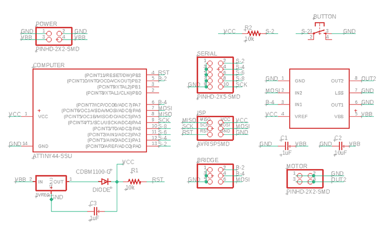
So my first step was to understand all the components in Greg’s board. I mainly cross referenced his with Neil’s H brige board and the other examples I found to piece together why he choose certain components. One question I had was why all the headers? I think I understand the additional headers to serve as further access to the ATTiny44 pins. The 2x5 header allows for serial communication. The first 2x3 header allows for programming the ATtiny44, the second 2x3 header allows for programming the H Bridge component. I will remove the LEDs and the Crystal and associated resitors and capacitors from Greg’s board.
Board Schematic and Design
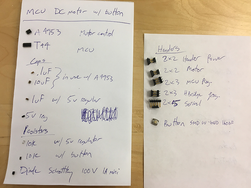
Here are my components:
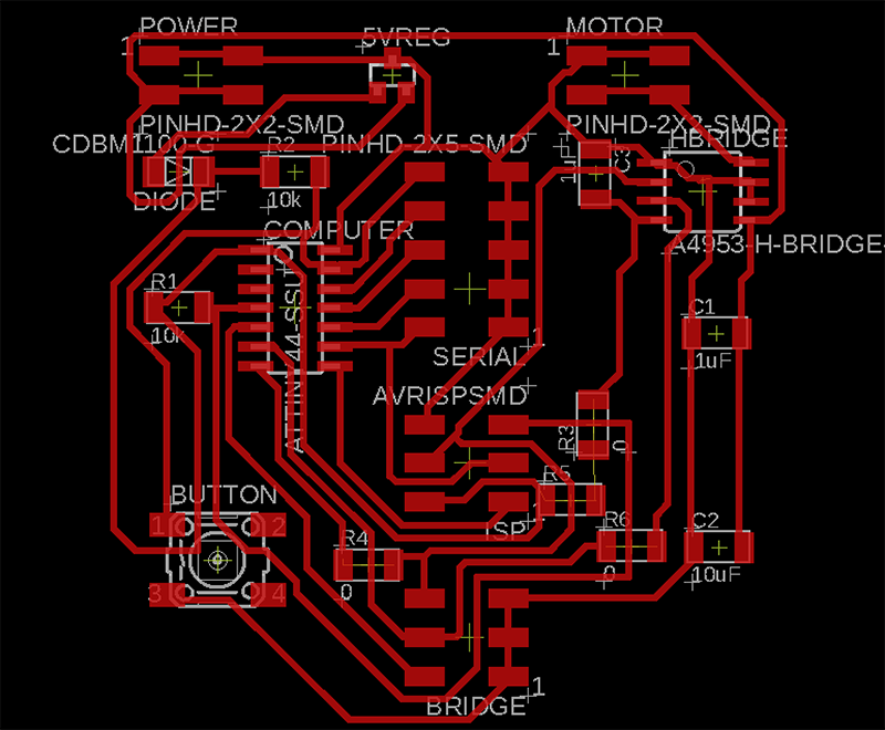
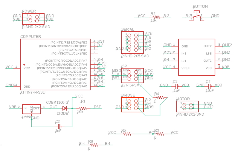
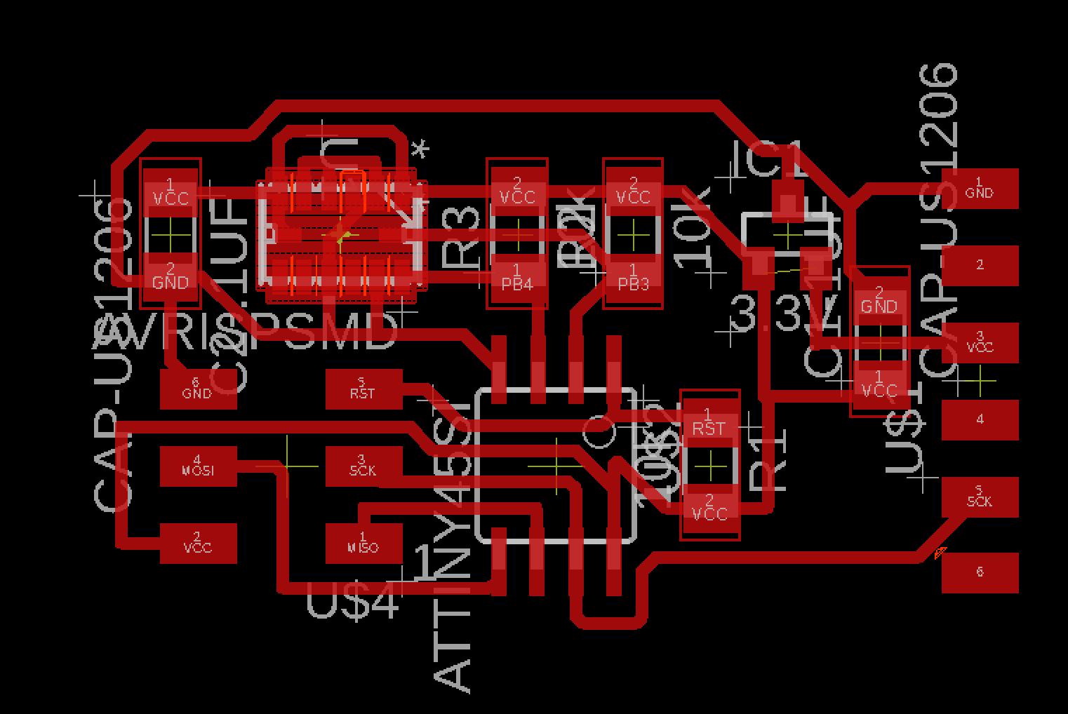
Here’s my Eagle Schematic: I see that Greg has some new techniques for connecting components. He’s uses the nets plus direct connections that have green dots at the intersections. Perhaps this allows for multiple things to be connected to each other?
My first step was to thoughtfully name each component. It helps understand what is going on with the board.
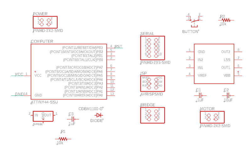
One question that came up is about have 2 different power needs. I now see that the motor driver is labeled VBB and the ATTiny44 power is labeled VCC. The 5V regulator should allow for using the same power source for both without frying the ATTiny44 - which I think has a lower power capacity.
Naming the nets gets a little tricky when you have 2 or more connections on the same line. Which component port is more important: MOSI or IN2, for example? I guess the consistency is th emost important thing.
Schematic 1
Here’s my schematic before designing/arranging the board, we’ll see how it stands up:
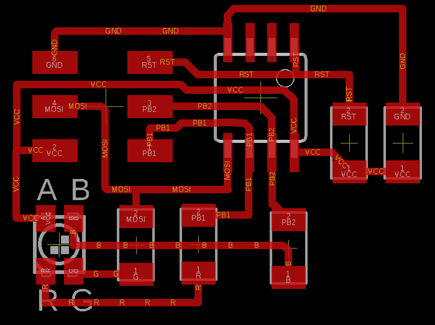
Board Design 1
Here’s my Eagle Board: I used autoroute for the first time! Before, I was manually routing my boards. It’s nice to know this gets you pretty far! I’ve done a couple different passes now, here’s a screen shot of the latest. Make sure to select N/A for the double sided board.
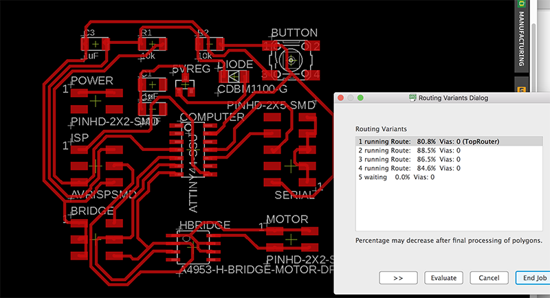
 I learned to not autoroute on top of another autoroute. I first did autoroute, then move the components around and tried to autoroute again, but it didn’t solve anything and made a bigger mess.
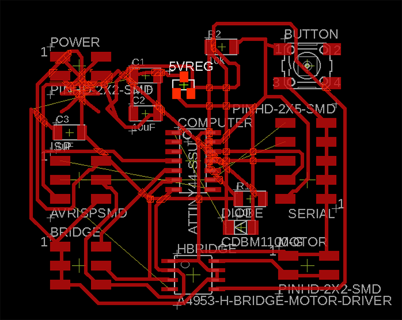
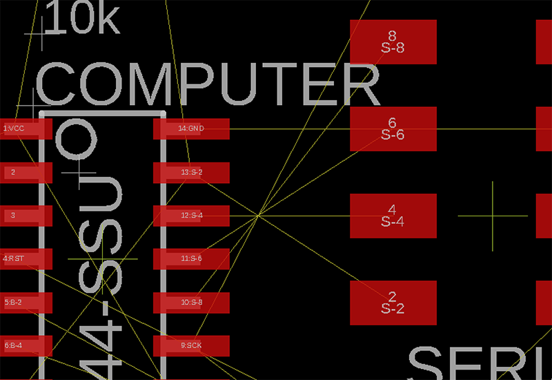
I’ve tried autorouting at least 10 times now. Making small changes and trying again. I changed the setting for Effort from low to medium. Make that like 20 times. I’m giving up on auto-routing. I will attempt to more closely copy Greg’s layout and go from there. I did notice this problem of having the opposite order from top to bottom (notice s-2, s-4, s-6, etc is in the opposite order on the ATTiny44 and the 2x5 header - see below). I will reverse it in the schematic and try again.
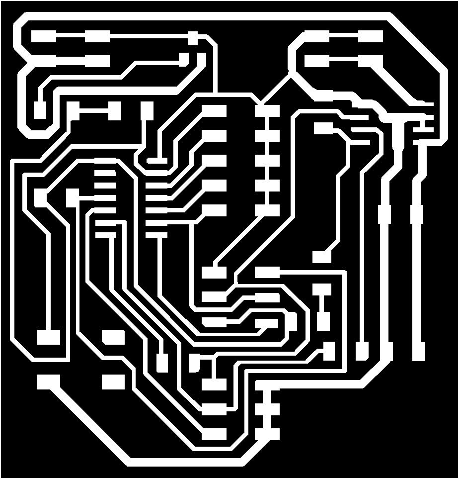
I think I got it! I had to use 4 jumper resistors:
I modified the paths quite a bit in Photoshop to do my best to ensure everything gets cut out - that it’s not too small.
Schematic 2
Here’s my final schematic showing additional 0ohm resistors to jump over the routes where needed. It definitely took a lot of back and forth between the auto-router and manually adjusting paths.
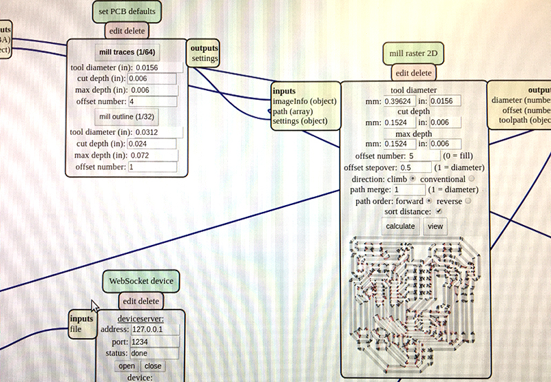
MODs Milling
Here’s the Roland/MODS settings I used. I found that a cut depth of .006 works better more consistently than .004.
Soldering
Soldered components on board:
I had to check the data sheet for the H-Bridge A44953 to verify what end was what. I also saw that the bottom of the component had a metal piece that could be soldered to the ground? I did make a large pad there on the board like Greg and Neil, but wasn’t sure if I should add extra solder too. we’ll see!
https://www.allegromicro.com/en/Products/Motor-Driver-And-Interface-ICs/Brush-DC-Motor-Drivers/A4952-3.aspx
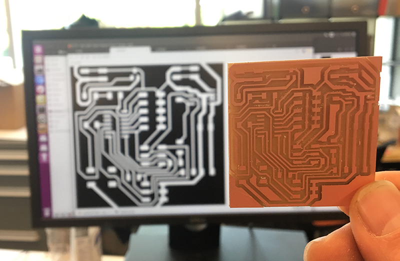
The board looks good out of mill - no missing/additional connections in the copper.
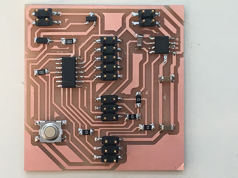
Here’s the first board, soldered:
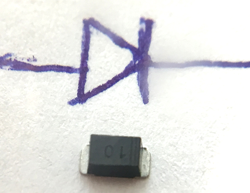
Make sure the diode is facing the right direction, using the double line marking to indicte the cathode end:
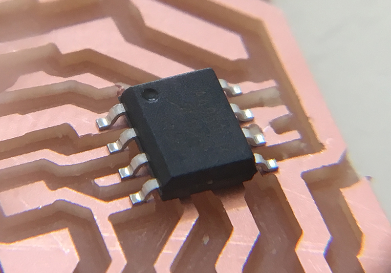
I got some deep cuts on this board. Here I’m confirming that my H-Bridge is in the right direction, with the circle on the upper left indicating ground.
Board Programming
Arduino Settings
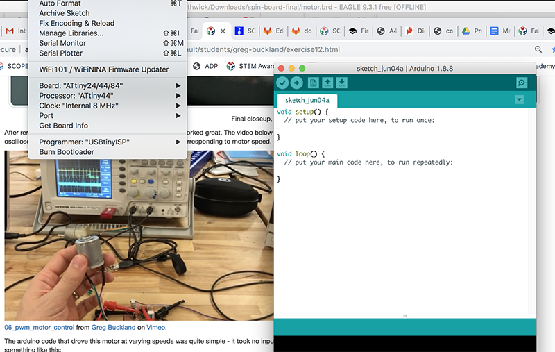 I forgot these settings and steps from the last time I did this, so this time I took a screenshot to remember!
Learning moment! When doing bootloader in Arduino, make sure you set the clock to internal if you are in fact using the internal occilator! We learned that you can cause major - hard to undo - damage to a board if you select an external crystal and bootload that. You can’t just resend the bootload with the correct internal clock. I ended up having to remove the original Attiny44 and replace it and resolder a new one.
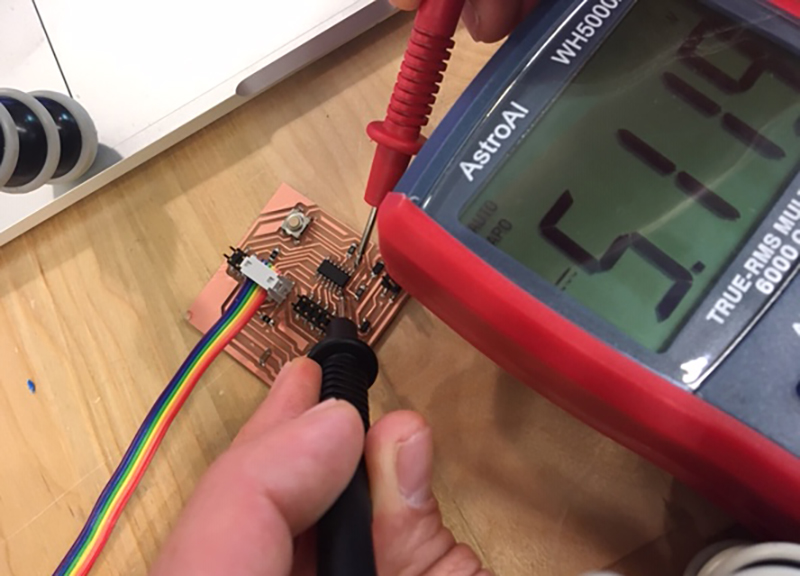 Here I am trouble shooting the ATTiny44 after mistakeningly bootloading with a 20mhz external crystal. It was still getting power, but it appeared that the fuses had been set.
Here’s the code I borrowed from Greg’s Week 12 code, slightly modified. I specifically reduced the number of cycles, changing the counterMax to adjust for my motor stages.
//this one toggles through a preset list of speeds in one direction
//and then toggles through the speeds in the other direction
//each button press advances through the list:
//[off, slow, medium, fast, off, slow-reverse, medium-reverse, fast-reverse]

#define in1 6
#define in2 7
#define buttonPin 0
#define off 0
#define slow 100
#define medium 175
#define fast 255

int counter = 0;
int counterMax = 4;
int buttonState = 0;

void setup() {
  pinMode(buttonPin, INPUT);
}

void loop() {
  // put your main code here, to run repeatedly:

  buttonState = digitalRead(buttonPin);   //read the button

  if (buttonState == LOW){    //if button is pressed
    delay(200);     //give user time to press and release button
    if (counter >= counterMax)    //if counterMax is reached
      counter = 0;      // reset counter to 0
    else
      counter++;      //otherwise, increment counter by 1
  }

  switch(counter){
    case 0:
      analogWrite(in1, off);
      analogWrite(in2, off);
      break;
    case 1:
      analogWrite(in1, fast);
      analogWrite(in2, off);
      break;
    case 2:
      analogWrite(in1, off);
      analogWrite(in2, off);
      break;
    case 3:
      analogWrite(in1, off);
      analogWrite(in2, fast);
      break;
    default:
      analogWrite(in1, off);
      analogWrite(in2, off);
      counter = 0;
      break;
  }

}
Here’s the final code I ended up using. It’s simplified from the code above. A button click turns the motor on full power in one direction and then another button click turns it off. I realized that the machine performed better if I just gave it full power (instead of gradually ramping up from slow to medium to fast).
//code by Daniel Smithwick 2019
//this code is modified from Greg Buckland 2018 Fab Academy
//this one toggles through a preset list of speeds in one direction
//each button press advances through the list:
//[off, fast]

#define in1 6
#define in2 7
#define buttonPin 0
#define off 0
#define slow 100
#define medium 175
#define fast 255

int counter = 0;
int counterMax = 2;
int buttonState = 0;

void setup() {
  pinMode(buttonPin, INPUT);
}

void loop() {
  // put your main code here, to run repeatedly:

  buttonState = digitalRead(buttonPin);   //read the button

  if (buttonState == LOW){    //if button is pressed
    delay(200);     //give user time to press and release button
    if (counter >= counterMax)    //if counterMax is reached
      counter = 0;      // reset counter to 0
    else
      counter++;      //otherwise, increment counter by 1
  }

  switch(counter){
    case 0:
      analogWrite(in1, off);
      analogWrite(in2, off);
      break;
    case 1:
      analogWrite(in1, fast);
      analogWrite(in2, off);
      break;
    default:
      analogWrite(in1, off);
      analogWrite(in2, off);
      counter = 0;
      break;
  }

}
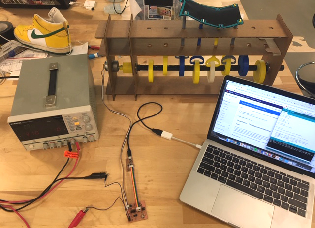
Motor Tests
My setup is the following: Use the DC Power Supply, sending 12V max, and allow for 3-5 amps. The power supply sends power to my board.
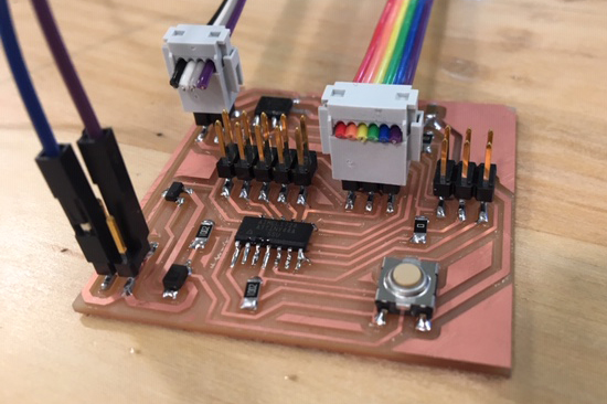
Here’s a detail of the board. This should help me remember the orientation of the plugs!
I finally got called on in lecture!
Neil gave me positive feedback about my Makeswaves machine. He recognized the core problem of contraining motion in the structure. He suggested considering diagonal bracing. Maybe. I have some other ideas in the works too:
sketches here.
Neil did pose an interesting challenge regarding the phenomenon of waves: group velocity vs phase velocity. Pretty neat: https://www.quora.com/What-is-the-difference-between-phase-velocity-and-group-velocity
https://en.wikipedia.org/wiki/Group_velocity - cool animation of the difference.
AC/DC power, Serial input keyboard motor control
This video shows how I can program the machine to recieve commands through the serial port from the keyboard.
OLD: Final Project Previous Ideas
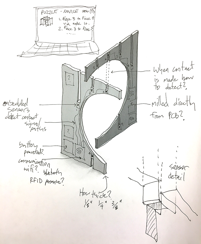
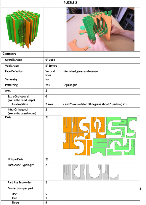
I plan to revive past research work on interactive cognition by making multi-planar interlocking puzzles that can be electronically tracked. I want to embed sensors into each puzzle piece to be able to track movements and connections with other pieces. something very low power/profile, but i could see the pieces thickening as needed to accommodate innards.
Here’s my original conception of the puzzles:

Input / Output?
My instructor asked, “what will be the “input” and “output” devices? i.e. what will the puzzle sense or do?” This is where some new ideas/skills from taking Fab Academy will come into play. He also suggested: “A great opportunity to do some advanced networking between the devices too. As for material thickness, you might be right. But you also might be able to get creative - the PCBs themselves can get pretty thin.” The output would be some sort of analysis of the puzzle being solved…overall speed, number of moves, incorrect placements, rotations, etc. Perhaps this is collected and/or displayed on a website?
Sketches
Right now i’m kind of seeing this as a research device that can track interactive cognition. But I could also imagine gaming opportunities, or making this more of a learning toy/product.
This image suggests that thinking may operate differently at different scales, which may come into play later in the course - How to make this puzzle 4 feet cubed?!
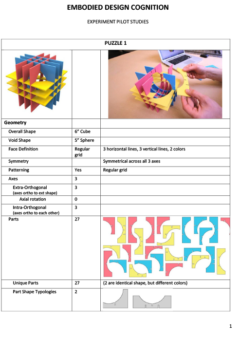
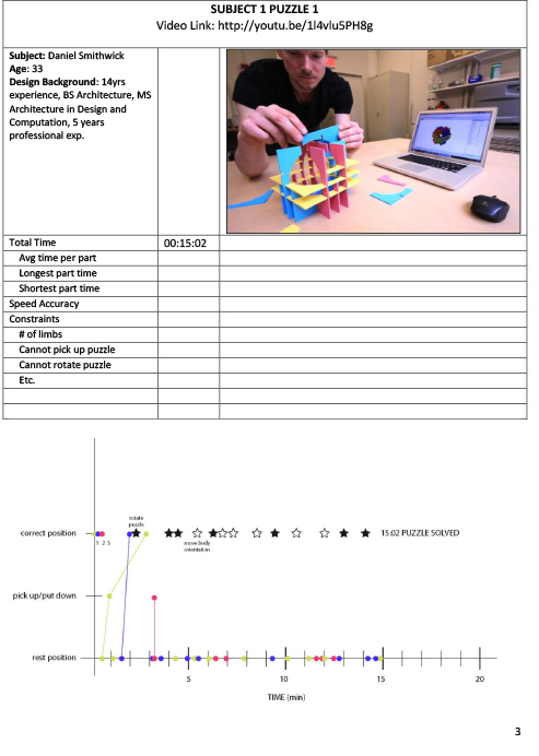
Research Background
Videos This video shows one subject completing a 2-plane puzzle rather quickly:
This video shows another subject completing the same puzzle rather slowly:
Documentation (I’d like to automate this with the electronics)
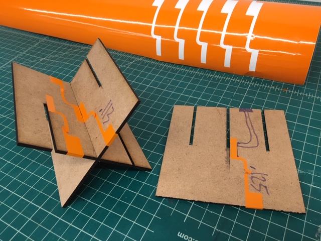
Laser + Vinyl Mock-ups
In week 4 I used vinyl cut stickers to simulate a circuit that spans perpendicular parts:
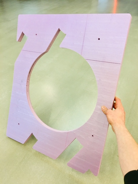
Oversized Laser Cut Acyrlic Prototype
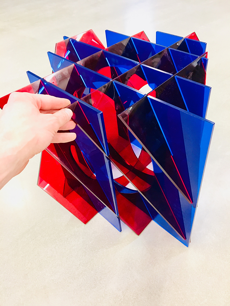

Maybe Go Big?
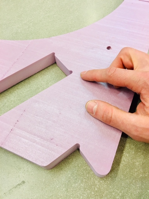 Here’s a detail of the dog bone design - a modified ‘H’ section. I’ve also added fillets to the all exterior corners to mimimize breakage.
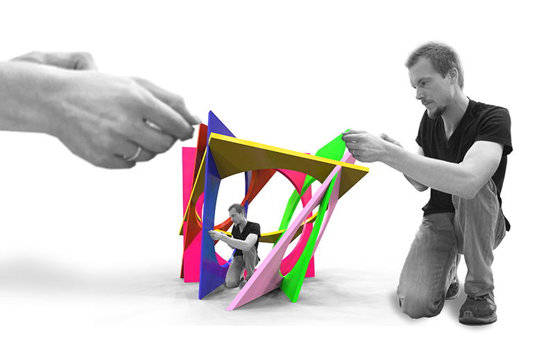
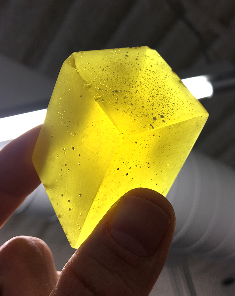
Switching Project Ideas - Finding beauty in the Parallelepiped
Perhaps do embedded sensors inside casted plastic piped shapes?
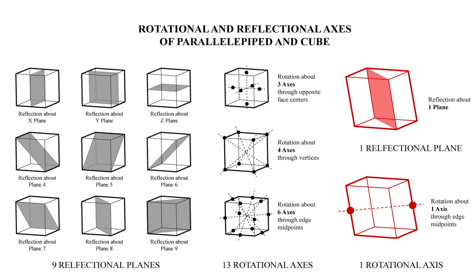
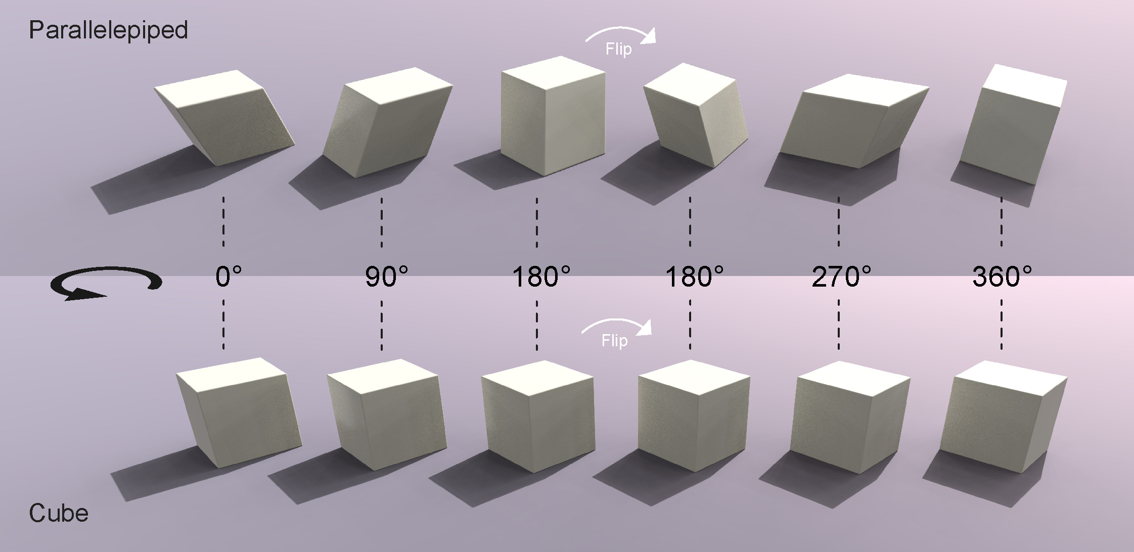
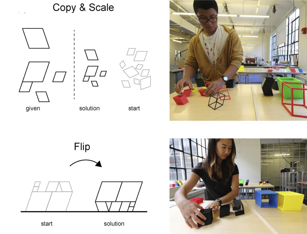
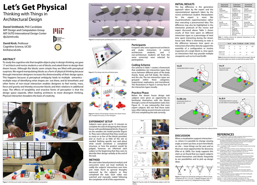
CogSci paper I wrote based on parallelepiped geometry: https://mindmodeling.org/cogsci2015/papers/0385/index.html
Accelerometer board design:
+
RGB board design:
What’s needed is a Hall sensor board with the RGB LED board.
Proximity Detection? With groups of blocks?
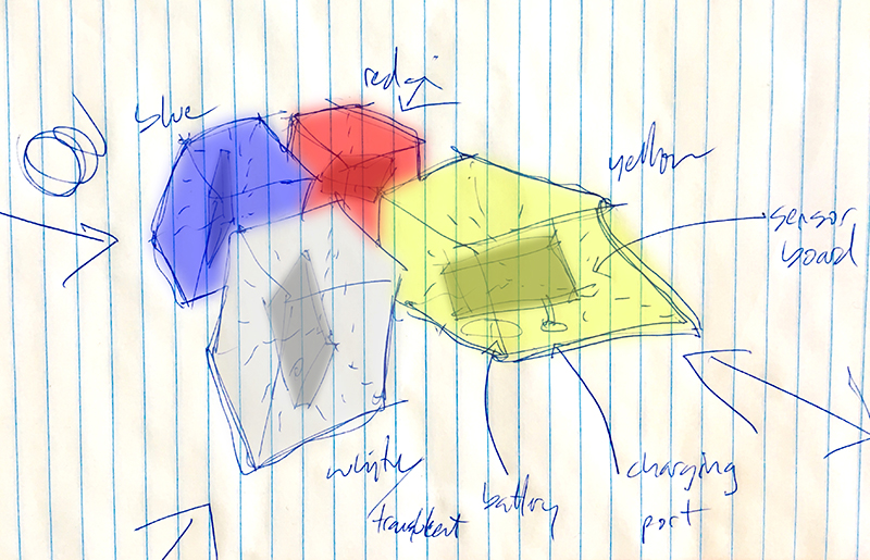
The working idea for now is to embed a proximity sensor in each piped block that would detect how close it is to another piped block. If time permits I can add sophistication to detecting the relationship of one block to another such as a reflective symmetry or a translation.
Maybe I set a goal of having 4 blocks with sensors that can detect each other and glow from within to indicate sensor readings.
Orientation Detection?
What if each block would change color based on its NSEW orientation? If the block is facing north it is blue, south is orange, east is yellow, west is violet. Or North is blue, East is red, South is yellow, west is green?
This project will involve 3d modeling, mold making and casting, cnc milling, electronics design and production, and embedded programming.
3D Modeling in Rhino
I need to revise old models (to get the best edge fillet radius for this scale) and/or start new ones. need to dig through old hard drives.
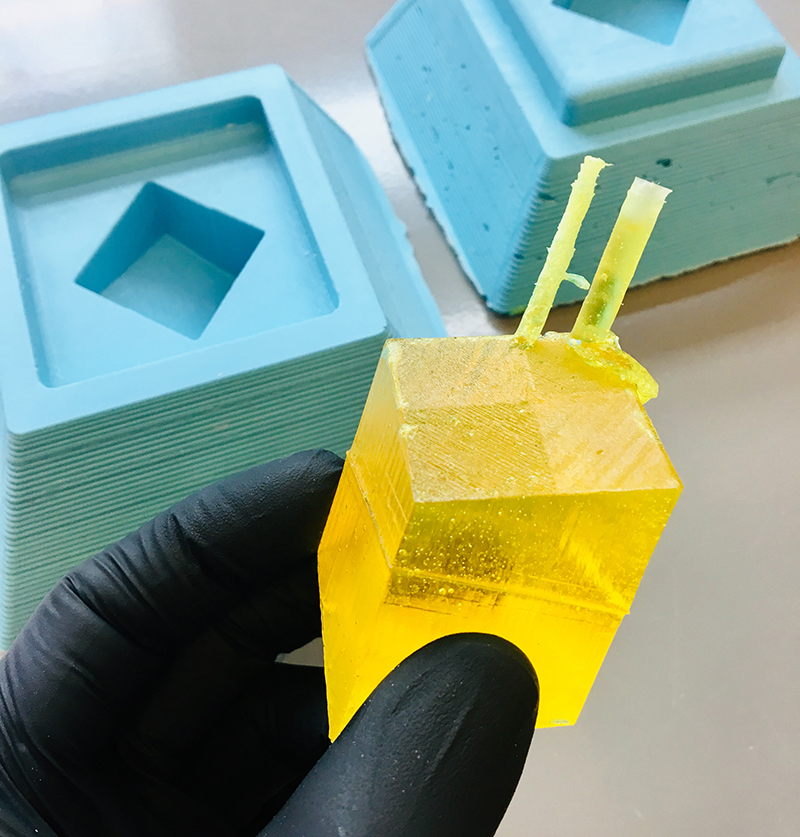
Molding and Casting
Use 3d print as mold? or milling the wax again? I wasn’t too impressed with vcarve. Would need to look into Need to embed the sensor board into the mold. How to suspend?
How big does the block need to be? Can the casting materials interact with the battery and electronics?
These materials will be the biggest cost.
Electronics Design - Input
Hall sensor to detect magnetic fields and the earth’s field? how to get NSEW orientations? Need power - battery? How to charge battery over time? Do I need a charging plug?
Big Question: how to suspend the sensor board and battery and charging port within a cast plastic block?
Programming - Output
LED lights to turn colors based on orientation
What are the rules of interaction?
Each block is translucent white to begin…changes color based on its relationship to neighboring blocks.
This kind of reminds me of the Temple of Doom Sankara Stones!

Process / Schedule
start with electronics, scope out parts, design new board, get general idea. after 2 weeks move on to molding and casting using a generic shape of circuit board, working or not. then come back to electronics, get battery charging working and orientation of sensor determined based on rules of interaction.