16. Interface and application programming
The Plan
This week the assignment is to write an application that interfaces with a user and an input &/or output device that I made. I will start with Neil’s javscript.
Ok scratch that. It’s now 3 weeks until my final presentation and I need to repriorize my time. My thinking now is to build something this week that will also support my final project. Part of my final requires a new board that can spin a motor at varing speeds - low, medium, high. I was originally considering using a knob to control the motor speed (and maybe I still can/will) but now I will give myself 2 weeks (not every day unfortunately) to design and build the board, program it, design and program a simple 6 button GUI.
My latest plan for moving forward is to utilize spiral development. I will first build a simple board with a button that can power up and power down a DC motor.This will serve as a first pass to get a operable board. I will then attempt to build from that a new board that can be controlled via a GUI. When I do that, I’ll document that here!
The Goal
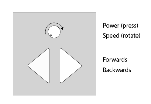 Here’s what I’d eventually like to control my machine for my final project. We’ll see if I can get here!
What’s Needed
I will base my interface development on Greg’s work from Week 12, to continue the progress I’ve made on the final project board. The first step is to get the serial connection up and running. I can follow that Greg took a couple of steps to get to the interface program. First connected his board via serial and wrote a new program to just read the input from the button.
I’m a little confused about the how the serial ftdi cable connects with the 2x5 header as it is currently wired up on my board. My concern is that the serial ftdi cable comes with power and ground, and my 2x5 header doesn’t connect to either of those. I can get power and ground elsewhere - through different pins/headers - but is there potential danger of sending power from the serial ftdi cable to the wrong ports of the 2x5 header and the attiny44.
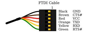 This is a helpful reference!
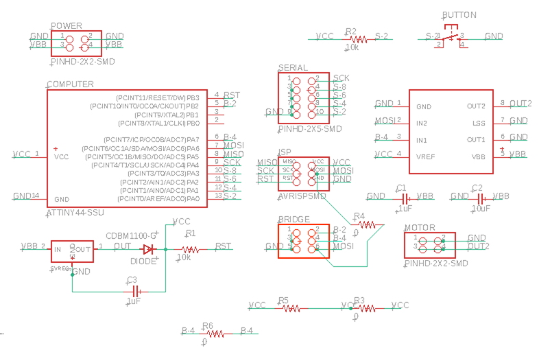
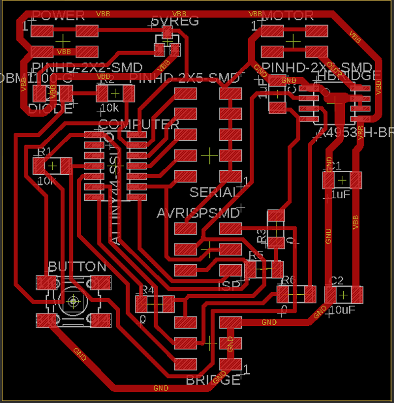
Below is my schematic and board design for the pin layout. You can see I’ve added some jumper 0ohm resistors to make this layout possible!
Files
I think my pins for the ftdi will be the following:
- TX = 10/s8/PA3 = yellow cable
- RX = 11/s6/PA2 = orange cable
- Button = s2/PA0 = brown cable
Serial Port Communication
Here’s the board code I’m adapting from Greg’s Week 12 work, paying attention to my Rx and Tx and button pins. (My PA3 and PA2 were reversed from Greg’s.)
//Counts button presses and sends the count over serial connx

//The following lines of code modified from:
//https://www.hackster.io/porrey/easy-serial-on-the-attiny-2676e6

#include <SoftwareSerial.h>
// ***
// *** Define the RX and TX pins. Choose any two
// *** pins that are unused. Try to avoid D0 (pin 5)
// *** and D2 (pin 7) if you plan to use I2C.
// ***

#define TX    3   // PA3, pin 10, white cable
#define RX    2   // PA2, pin 11, green cable

// ***
// *** Define the software based serial port. Using the
// *** name Serial so that code can be used on other
// *** platforms that support hardware based serial. On
// *** chips that support the hardware serial, just
// *** comment this line.
// ***
SoftwareSerial Serial(RX, TX);

//end quoted code

#define buttonPin 0

int counter = 0;

void setup() {
  // put your setup code here, to run once:
  Serial.begin(9600);
  Serial.println("Starting serial communication...");
  Serial.print("Counter: "); Serial.println(counter);
  pinMode(buttonPin, INPUT);
  delay(200);
}

void loop() {
  // put your main code here, to run repeatedly:
  int buttonState = digitalRead(buttonPin);

  if (buttonState == LOW){
    delay(200);
    counter++;
    Serial.print("Counter: "); Serial.print(counter); Serial.println("");
  }
}
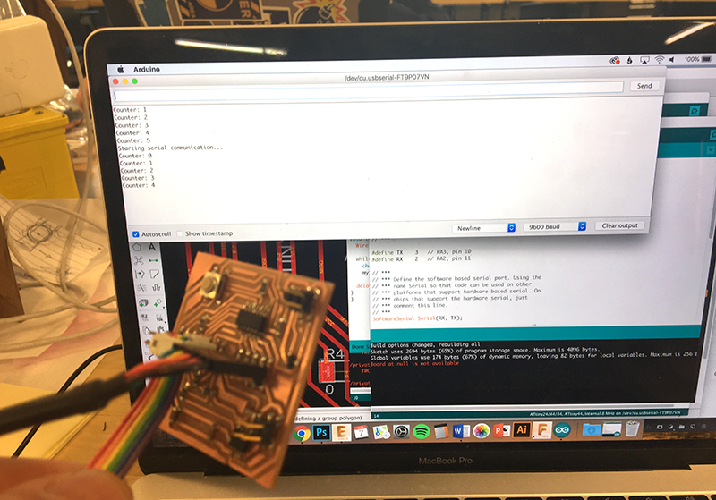
Serial Port Reading
It worked! Here’s a photo for now: 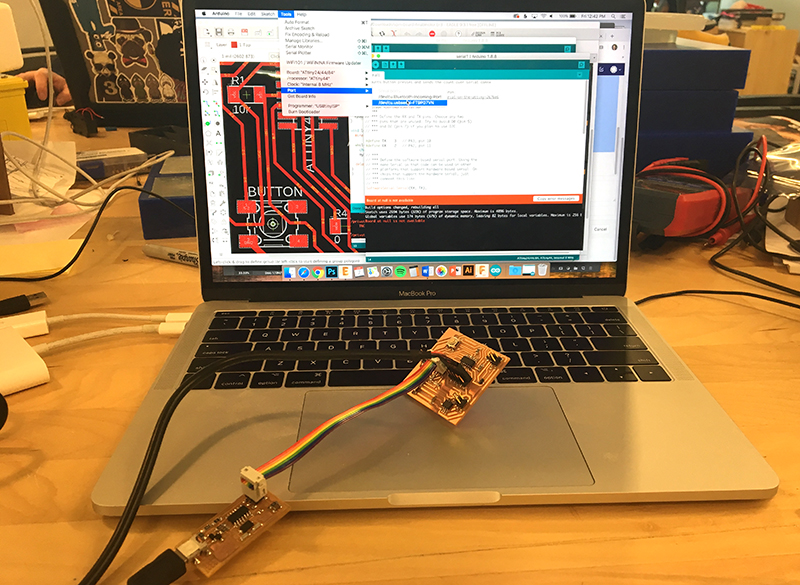
Quick Lessons
Be sure to connect to the serial port in the arduino settings. Also make sure you have the right board selected! After I uploaded the program, I opened the serial Monitor and then hit the button on the board and it work! I’m getting power and ground elsewhere - from the FabISP usb connection, so apparently the serial can still work with it!
Here’s the video of the setup, showing it working:
Pyserial Motor Control
I’m using Greg’s Week 12 code, modified for my ports, to allow serial input control of the motor using any values between -255 and 255.
// This version includes forward and reverse direction
// parses integers from serial buffer and sets as motor output
// negative integers lead to reverse direction, 0 turns motor off
// looks for values between -255 and 255. Numbers outside this range are
// interpreted as full speed (ahead for positive and reverse for negative)

// this version is for geared motor

#include <SoftwareSerial.h>

#define TX    3   // PA3, pin 10, white cable
#define RX    2   // PA2, pin 11, green cable
// #define bluePin 4 // PA4, pin 9, blue led
#define in1 6;  // PA6, pin 7 (-> in1 on A4953)
#define in2 7;  // PA7, pin 6 (-> in2 on A4953)

SoftwareSerial Serial(RX, TX);

//Following code adapted heavily from:
//https://processing.org/tutorials/electronics/
//includes excerpts from:
//http://forum.arduino.cc/index.php?topic=288234.0

//char val;             // Data received from the serial port //unused in this version
//char prevVal;         // the previous character received
bool newData = false; // store whether there's new serial data or not
int motorPin = in1;   // start the motor in the 'ahead' direction
int offPin = in2;
int power = 0;        //start the motor at 0 power

void setup() {
  Serial.begin(9600);       //Start serial communication at 9600 bps
  Serial.println("Go");     //signal to terminal that board is ready
  pinMode(bluePin, OUTPUT); //set bluepin for output
  analogWrite(motorPin, 0); //ensure motor is off
  analogWrite(offPin, 0);   //ensure reverse motor also off
}

void loop(){
  if (Serial.available() > 0) { //if serial buffer has data
    power = Serial.parseInt();  //parse the next valid integer from serial buffer
    power = constrain(power, -255, 255); //constrain speed to valid PWM range
    if (power > 0){   //if the power integer is positive
      motorPin = in1; //set the motor direction to forward
      offPin = in2;
    }
    else if (power < 0){  //if power int is negative
      motorPin = in2;     //set the motor to reverse
      offPin = in1;
    }
    power = abs(power);
    newData = true;             //note the presence of new data
    digitalWrite(bluePin, HIGH);  //blink the blue LED to alert user to new data
  }
  if (newData){   //if new serial data came in
    analogWrite(offPin, 0);   //turn off offPin
    analogWrite(motorPin, power);   //send power PWM to motorPin
    Serial.print("Power: "); Serial.println(power);
  }

  delay(50);    // Wait 50 ms for next reading
  digitalWrite(bluePin, LOW);   //turn off blue LED
  newData = false;    //reset newData boolean

}
Here’s the video showing the new power setup, running the above code.
I will now try to build the GUI, following greg’s page.
Python Tkinter GUI Development
Here’s a helpful refresher! It’s been a while since I’ve done Python
First, I tested the ports available on Terminal, typing:
python -m serial.tools.list_ports //will print a list of available ports.
My port was /dev/ttyUSB0
Got that working too - here’s the terminal screen shot:
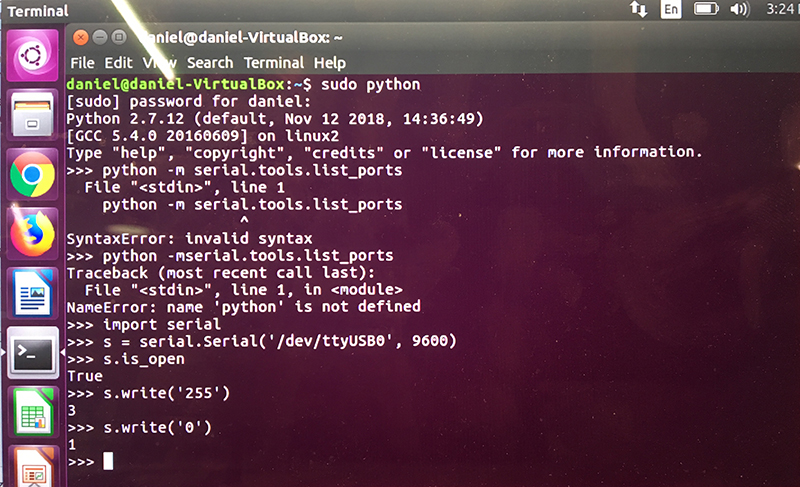
Minor error
One error I ran into was not having permissions on the port. I ened up starting Python with ‘sudo Python’ to get around the permissions.
Here is the python code I’m basing on Greg’s Week 12 work, slightly modified for my setup:
# Script for controlling DC motor using ATtiny44 and A4953 H-bridge chip

##  This code modified from Greg Buckland 2018
##  This section sets up the serial connection and imports
##  Tkinter  (GUI)functionality
##
import serial
from Tkinter import *

#Change this path to match your port:
ser = serial.Serial('/dev/ttyUSB0', 9600)

##
##  This section defines all the functions I will
##  call in my Tkinter interface
##
def all_stop():
    s1.set(0)
    update()
    print("Answering 'All Stop'!")

def full_ahead():
    s1.set(255)
    update()
    print("Answering 'MakesWaves Forward'!")

def full_reverse():
    s1.set(-255)
    update()
    print("Answering 'Makewaves Backward'!")

def toggle_direction():
    dir = -s1.get()
    s1.set(dir)
    update()
    print("Answering 'Switch Wave Direction'!")

def update():
    ser.write(str(s1.get()))

def quit():
    try:
        ser.write('0')
    except:
        print("Something wrong with serial connection")
    print("Exiting program")
    exit()

##
##  This section sets up the user interface
##
master = Tk()
b5 = Button(master, text='Set', command=update)
b5.pack()
s1 = Scale(master, from_=-255, to=255, length=600, tickinterval=100, orient=HORIZONTAL)
s1.pack()
s1.set(0)
b1 = Button(master, text='Makeswaves Backward', command=full_reverse)
b1.pack()
b2 = Button(master, text='All Stop', command=all_stop)
b2.pack()
b3 = Button(master, text='Makeswaves Forward', command=full_ahead)
b3.pack()
b4 = Button(master, text='Switch Wave Direction', command=toggle_direction)
b4.pack()
b6 = Button(master, text='Quit', command=quit)
b6.pack()

mainloop()
Interface Design
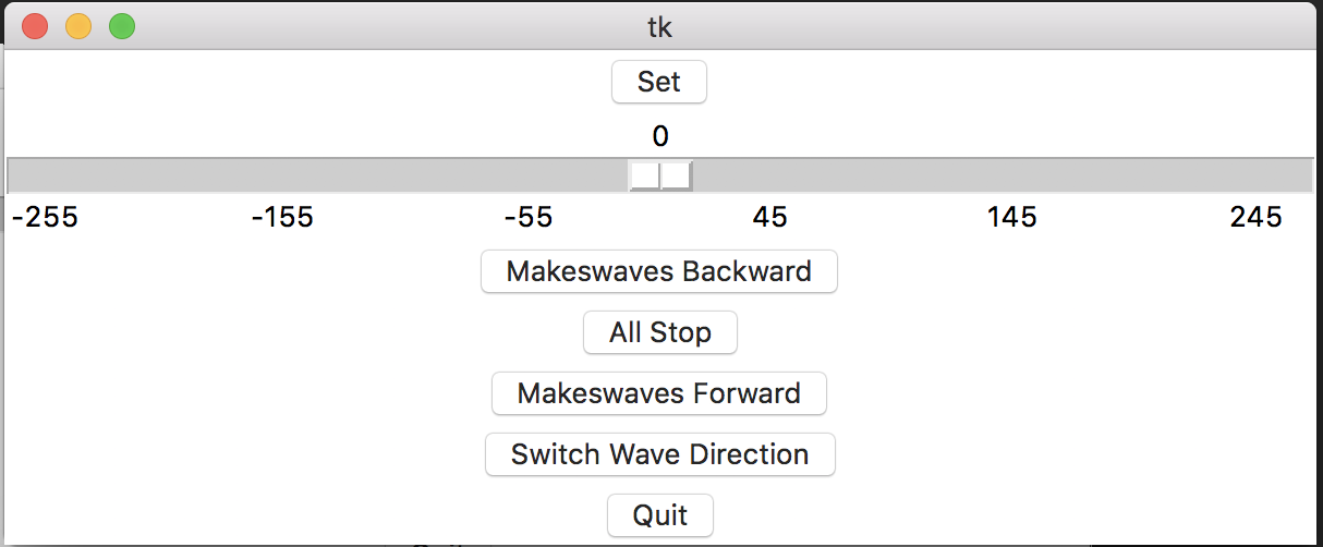 This design allows for full power in both motor directions.
Here’s a video showing the above code working:
I ran the code all within terminal using ‘sudo python’ to start python. I then just copied and pasted the code and it worked! I’ve modified the interface to make it my own, simplfying Greg’s original design.
Here’s a good link for Tkinter