7. Electronics design
EAGLE - downloadable files
This week I am installing Eagle software - an EDA - Electronics Design Automation and using it to redraw an existing circuit and adding two elements - a button and an LED. One question: why draw schematics? Why not just draw the physical components? It’s like an architect still drawing blueprints, no? Blueprints are now automatically generated from drawings and models of the actual 3D building parts.
I’m working through the Eagle tutorial now. It’s a little confusing, but I’m getting through it!
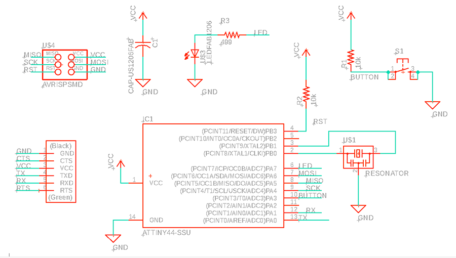 my first schematic!
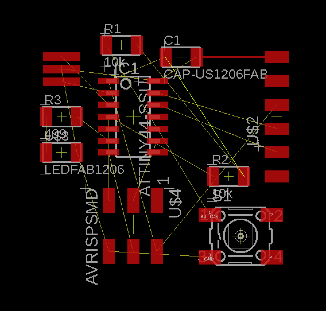 my first board, attempting to rearrange the components…
Eagle Schematic File Download Eagle Board File Download
Design Rules
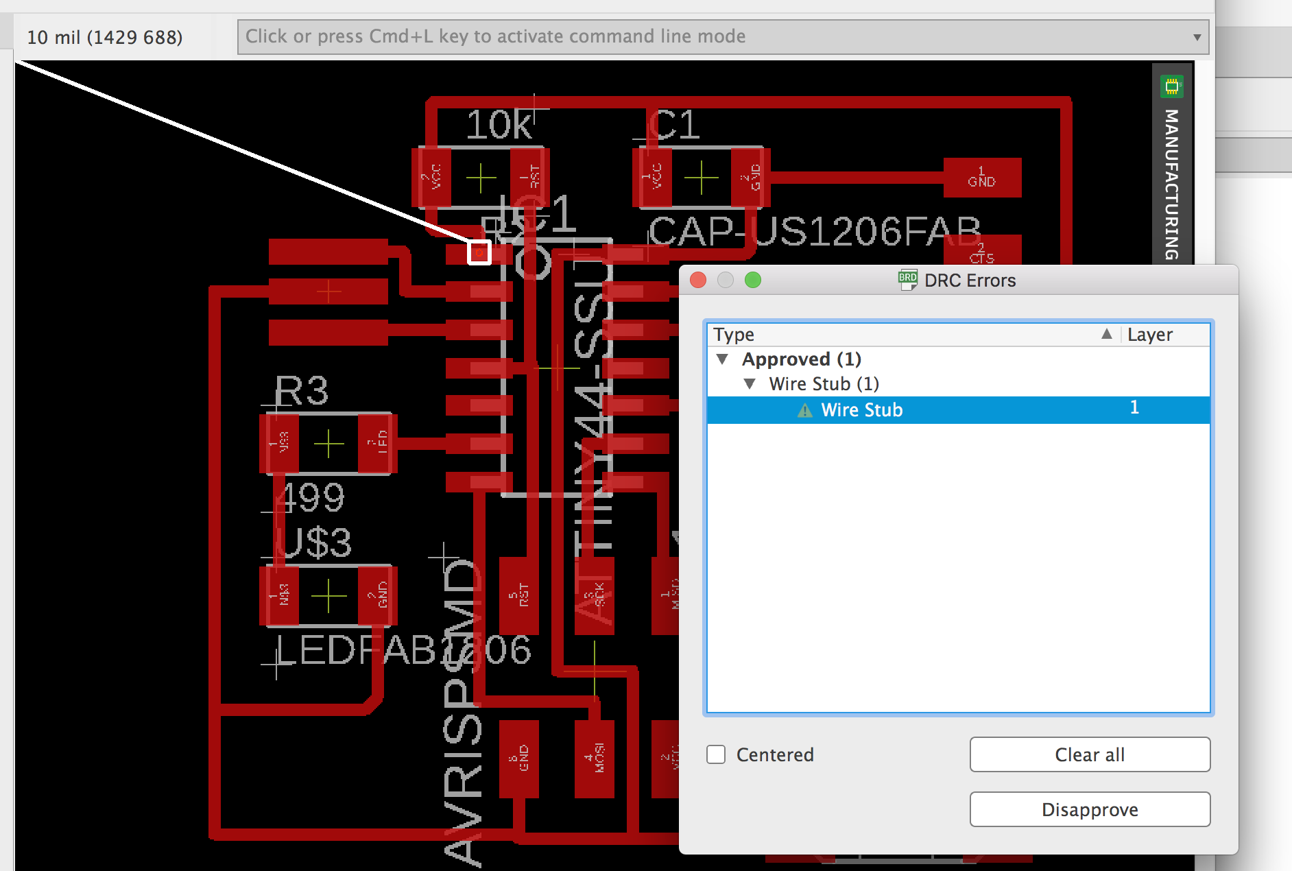 I received an error about wire stubs…i can delete them i think.
I tried installing the fabmodules.dru but without success.
png image
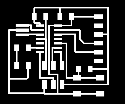 On my Mac Eagle did export the image 2X larger than it should have. I switched to Unbuntu to export the trace and boarder files to MODs.
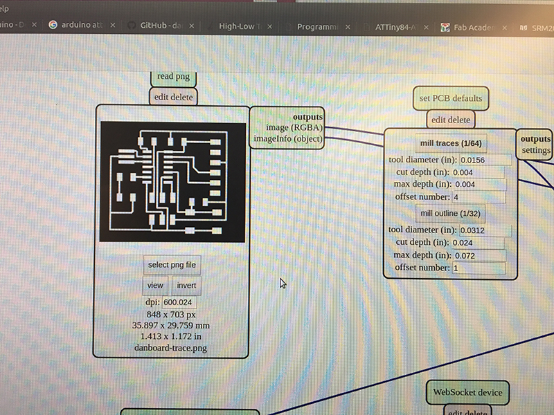
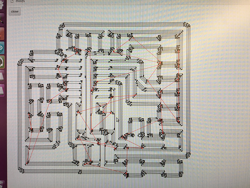
MODS
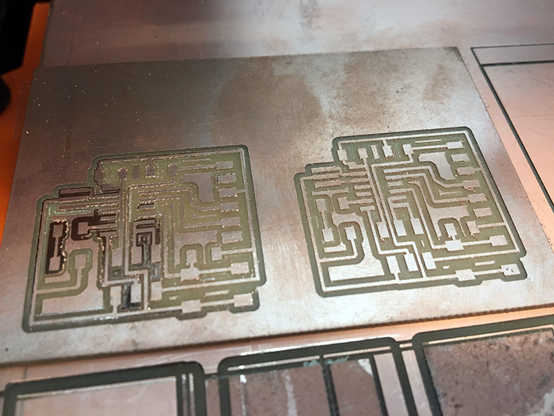
Roland Mill
ERROR: the first few areas weren’t cutting all the way through:
Soldering components
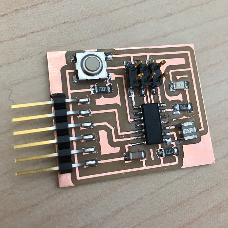
Test the board
I was getting the error from Arduino IDE: Yike! Check connections…
Turns out I had a couple of problems:
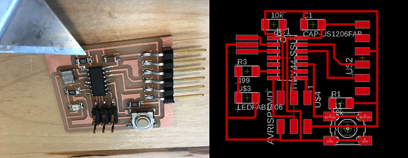 There was an errant line of copper connecting both ends of the resistor. This line wasn’t in the eagle board file, and it mysteriously showed up in the milled board. As you can see in the images above next to the razor blade, there was plently of room to mill between the resistor and the routing, so I”m not sure why the extra routing was included. I ended up removing the extra copper strip by hand, and the board worked.
This board did light up, but the button didn’t work as designed and unfornuately the 6-pin header broke off before I could test other programs…so please see my final project’s documentation of Electronics Design and Production for completion of this assignment.
Here’s a video showing the LED blinking:
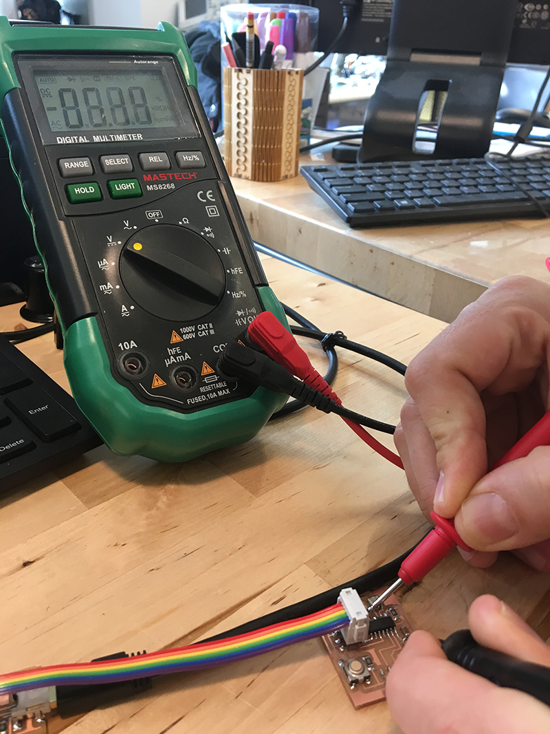
Group Assignment - Mulimeter and Oscilloscope
I also had the orientation of the LED wrong. I discovered this after using the multimeter to test the voltage. The voltage was as expected, which led to discovering the error with the LED orientation.