FINAL PROJECT PROGRESS
CONCEPT BRIEF:
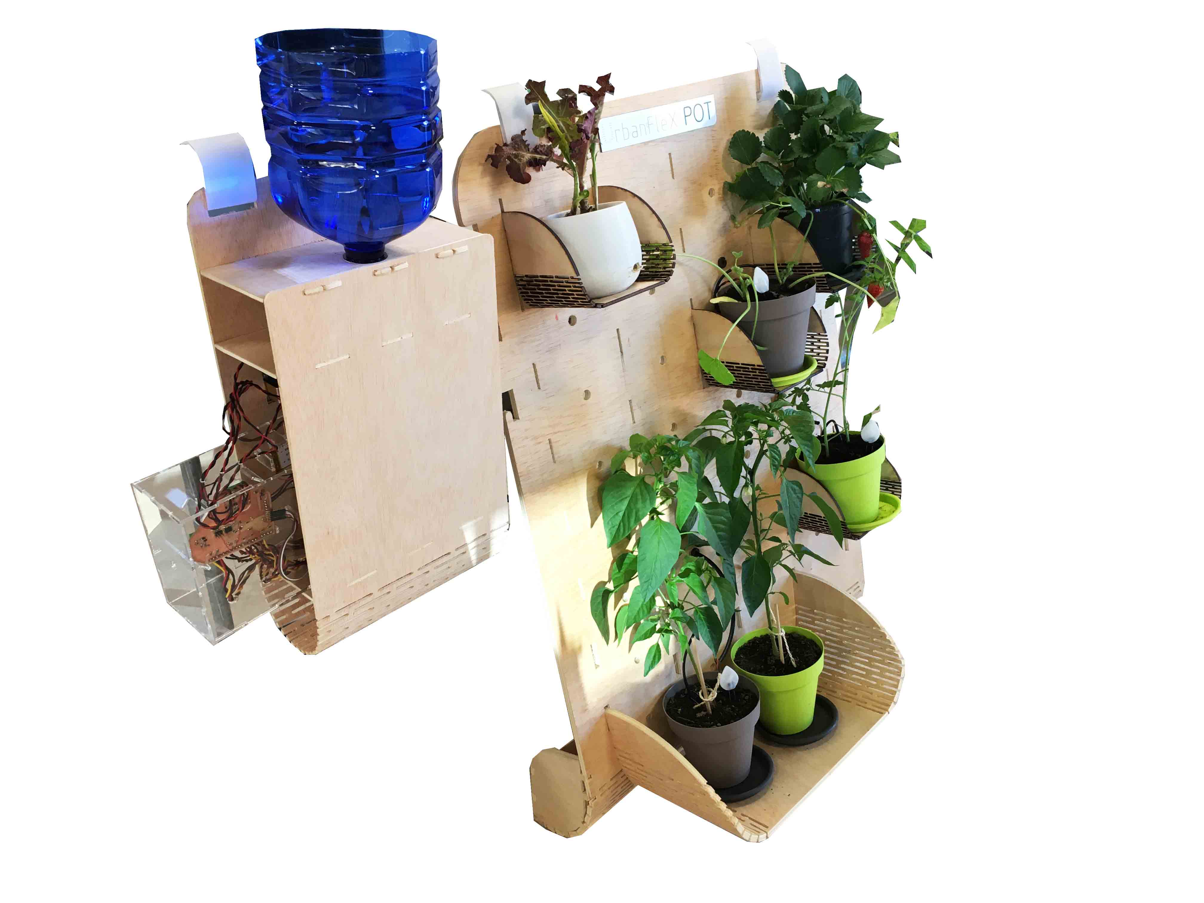
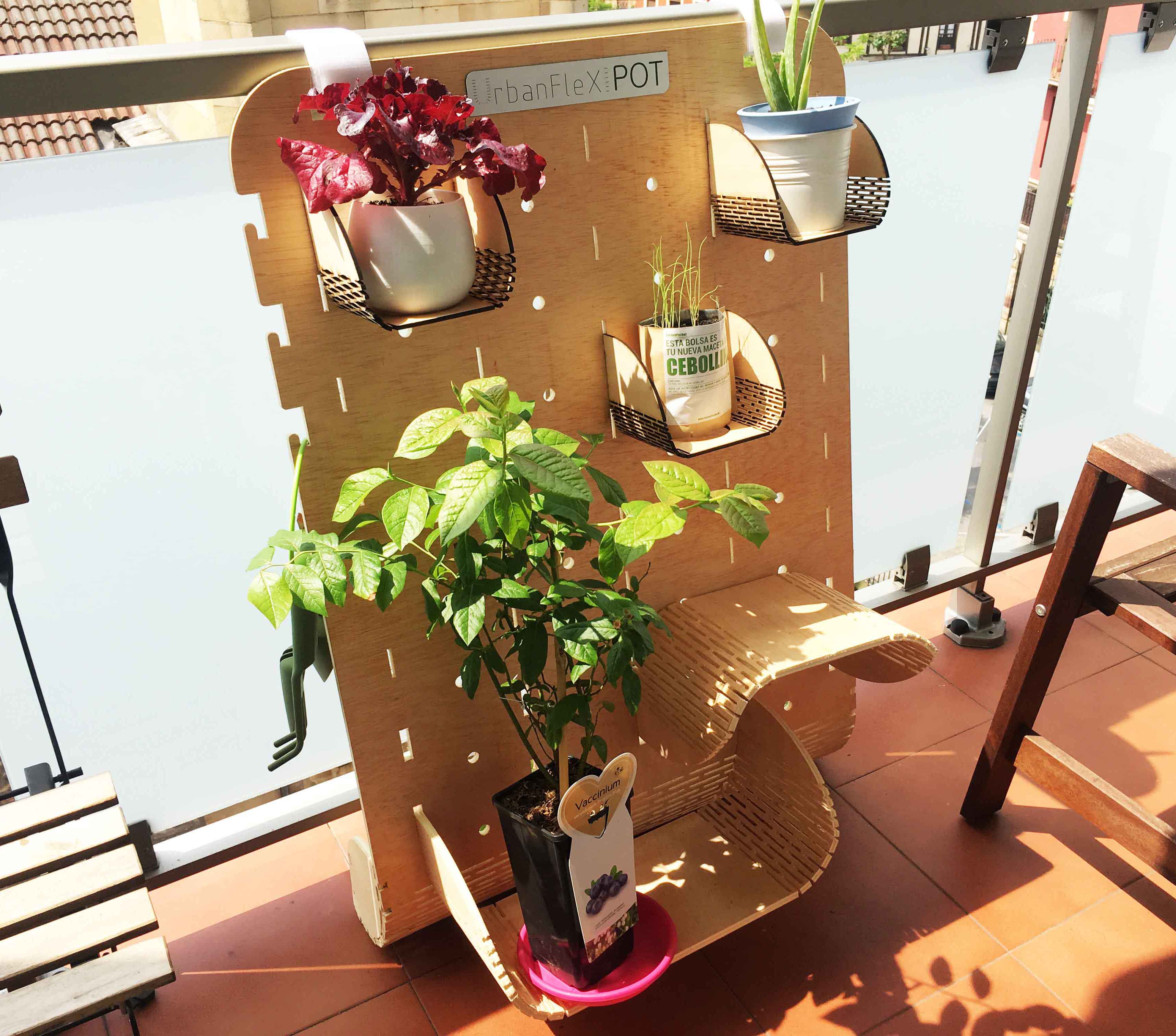
				- Customizable in size and number of pot holders.
				- IKEA Concept: Flat packaging and easy foldable in the assembly.
				- Easy assembly using Joints, without screws.
				- 4 automatic irrigation in the base module.
				- System based on adding modules.
				- 4 automatic irrigations added with each module.
				- It is going to be controlled with an App by user.
				- Small Flower-pot option, too.
In this area I will put everything related to each part/system that make up my final project, their development during FINAL PROJECT PROGRESS:
	1_MAIN STRUCTURE, MODULE and POT HOLDERS >> 3D Design, Laser Cutting and CNC Machining
	2_FLOWER-POT >> 3D Design and 3D printing
	3_MAIN PCB >> Electronics Design and PCB Fabrication
	4_WIFI PCB >> Electronics Design and PCB Fabrication
	5_PROGRAMMING >> Embedded Programming, Interface Programming, Networking and Communications
	6_INPUT AND OUTPUT DEVICES >> 2D Design and Laser Cutting
	7_USER INTERFACE >> 2D Design
	8_CONNECTING EVERYTHING >> Testing
	9_SYSTEM PACKAGING >> 3D Designg, 2D Design, Laser Cutting
	10_ASSEMBLY OF EVERYTHING >> Packaging and Integration
	11_TESTING >> Final Adjustments
	FUTURE PLANS >> Recognise opportunities for improvements in the design
All files, to download, are on the bottom of this site.
1_MAIN STRUCTURE, MODULE and POT HOLDERS
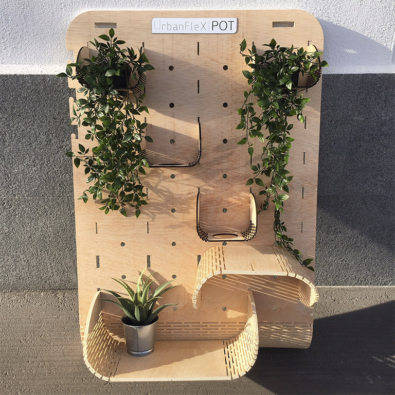
During week assignments I have been developing UrbanFlexiPot different parts. First of all I began to design and test main structure and pot-holders, and their press-fits and functionalities.
I began to design my final project main parts in Exercise 03. Computer Aided Design; I prepared main structure and pot-holders 1st 3D model, parametric designs, and Living Hinge templates, for doing them later on different fabrication methods.
During Exercise 04. Computer Controlled Cutting; I made first Livinge Hinge tests and some model prototypes in a little scale, in Laser Cutting machine.
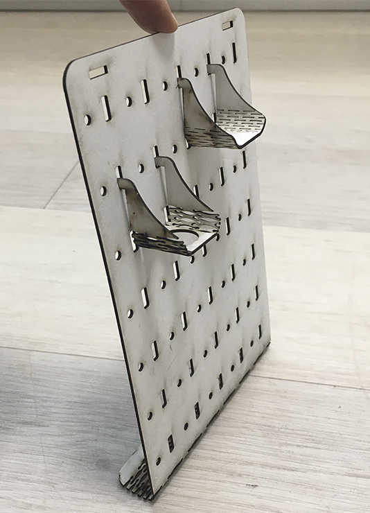
In Exercise 08. Computer Controlled Machining; I took advantage to prepare 3D and 2D files (model and livinge hinge templates) to machine them (corners and digital joints), machine and test them. In this way I tested the assembly and the Presss-Fit between the different parts of the design.
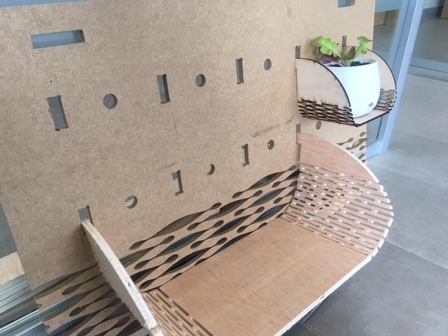
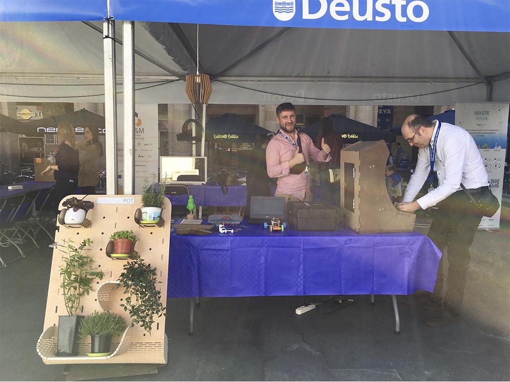
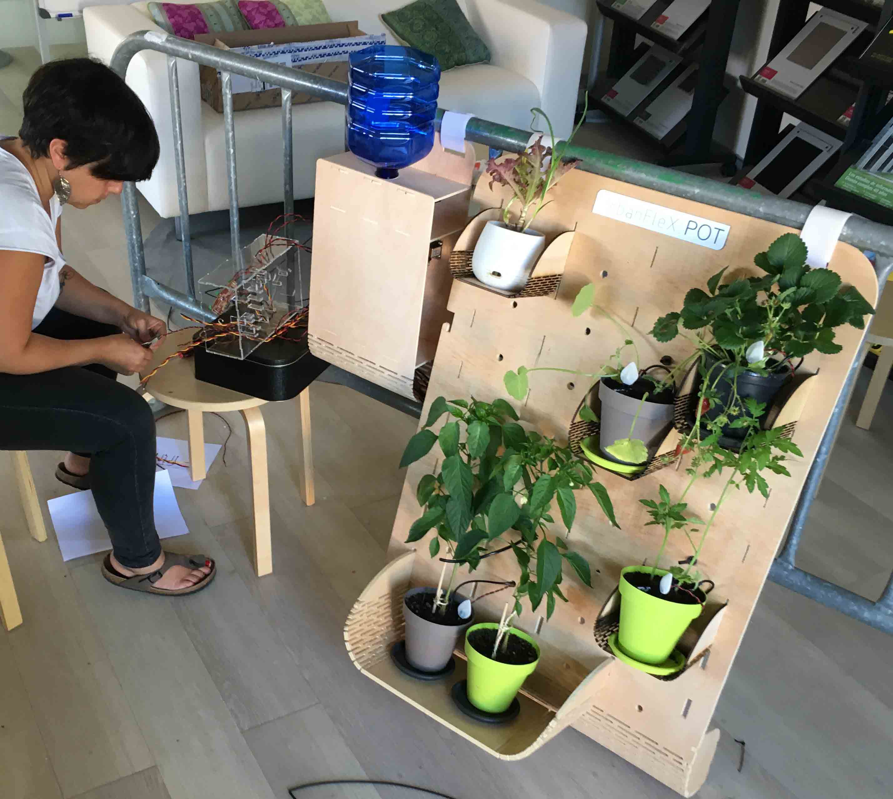
While Exercise 13. Interface and Application Communications; I took advantage of the fact that we had to attend an event, the science fair in Bilbao, to have a prototype at a 1: 1 scale, and to test the opinions of the people who came. People was very interested on it and gave me strength and conviction to continue with the concept.
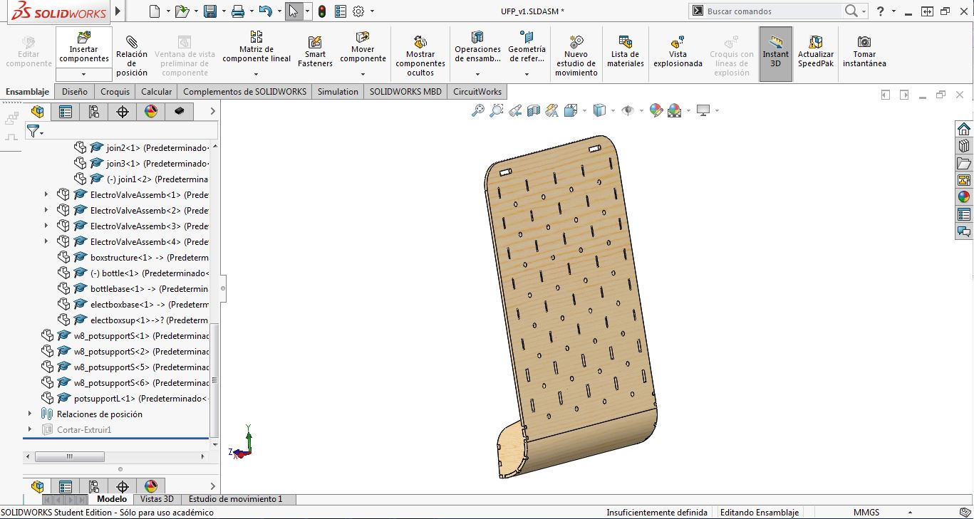
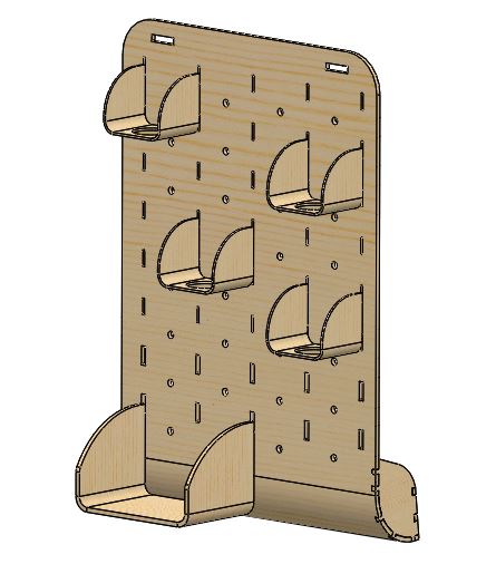
As I explain in all those assignments: The main design is done by SolidWorks, in 3D, prepared to its assembly. It is a parametric design file, which allows us to have a customizable product depensing on users balcony dimmensions or needs. Then, I take 2D from this designs, in DXF, and I add Living Hinges using Rhinoceros.
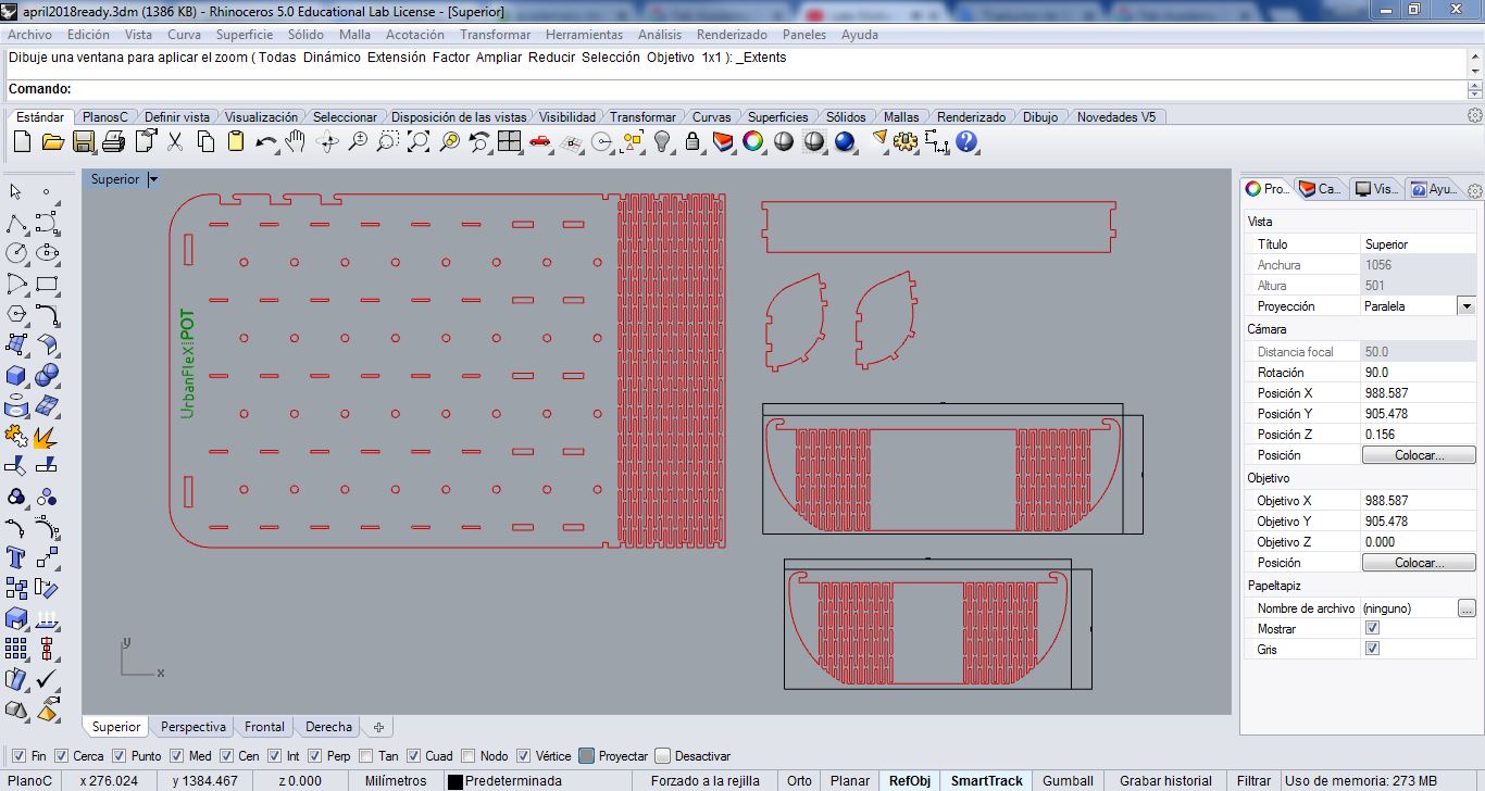
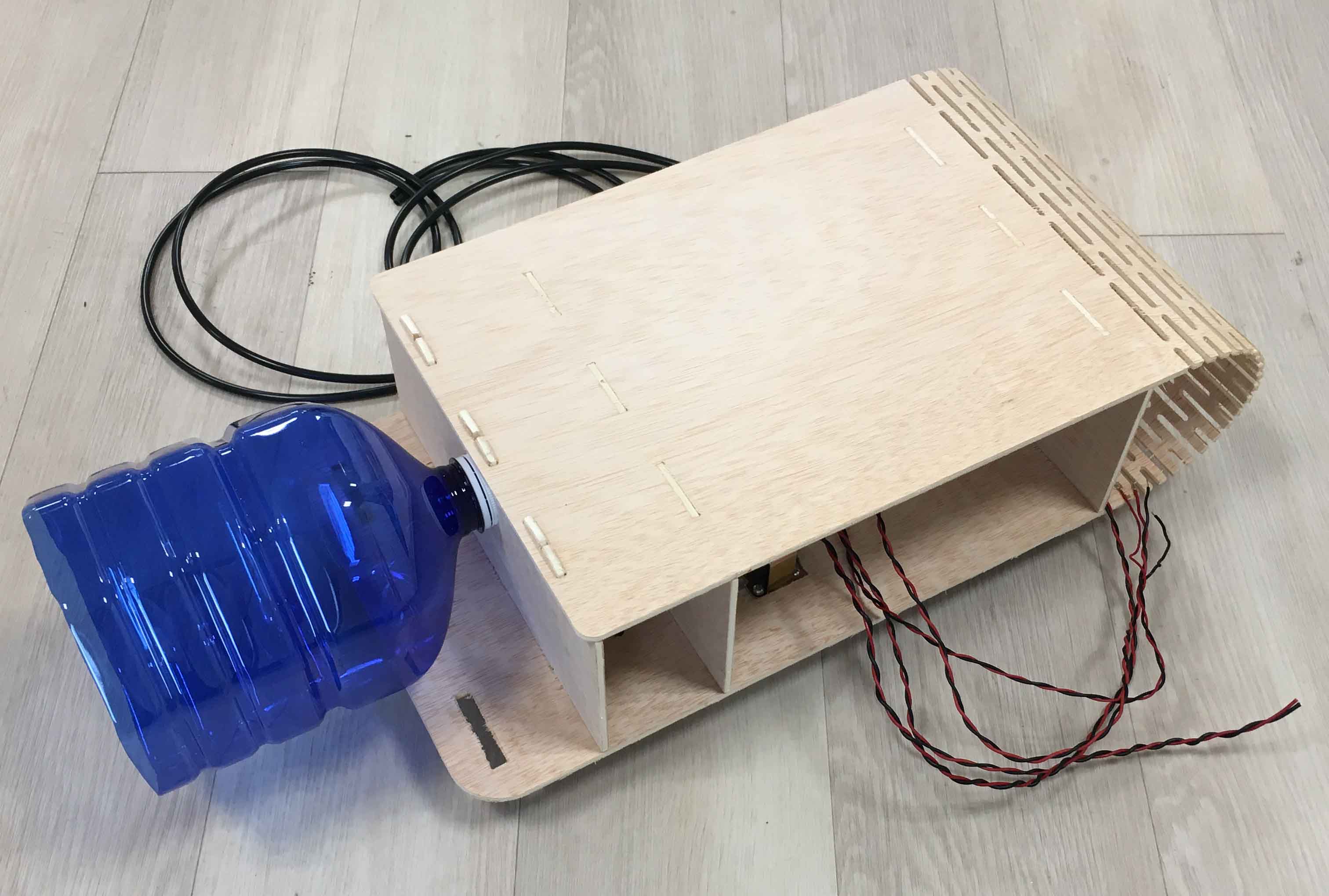
For Electronics and watering system MODULE, that I have designed and made in these last weeks, I have follow same method: Solidwork foldable design first, with Metal Sheet module, and livig hinges added later in Rhinoceros.
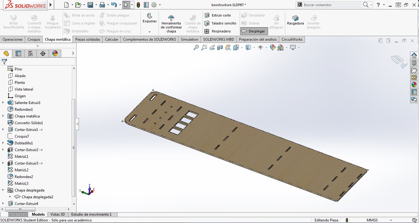
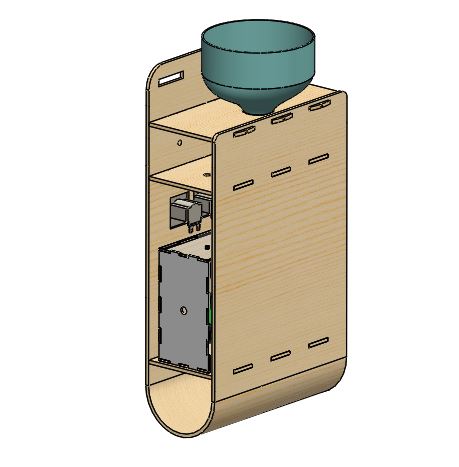
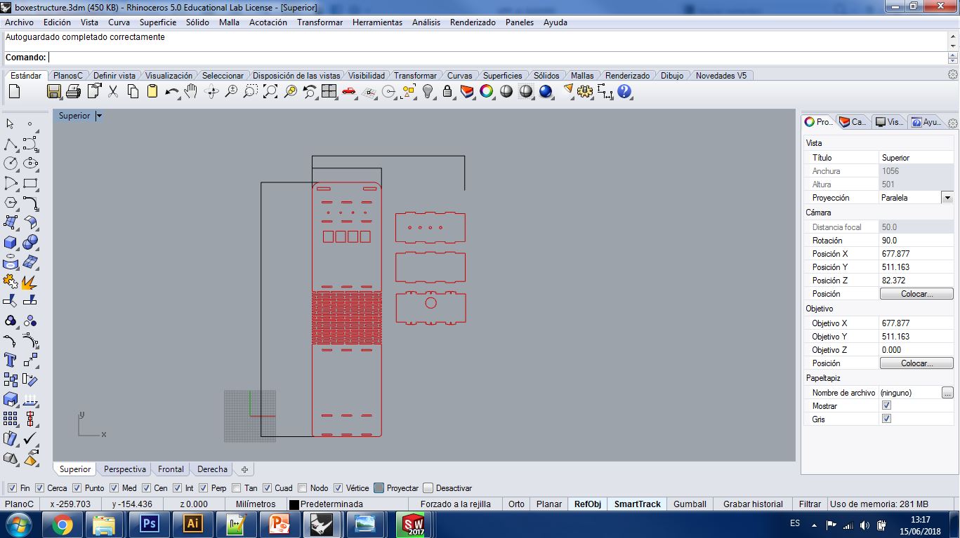
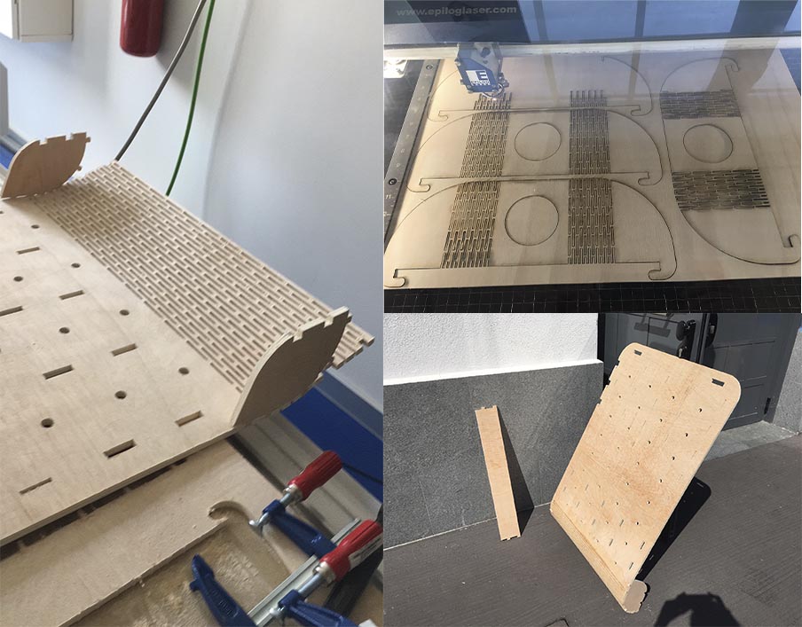
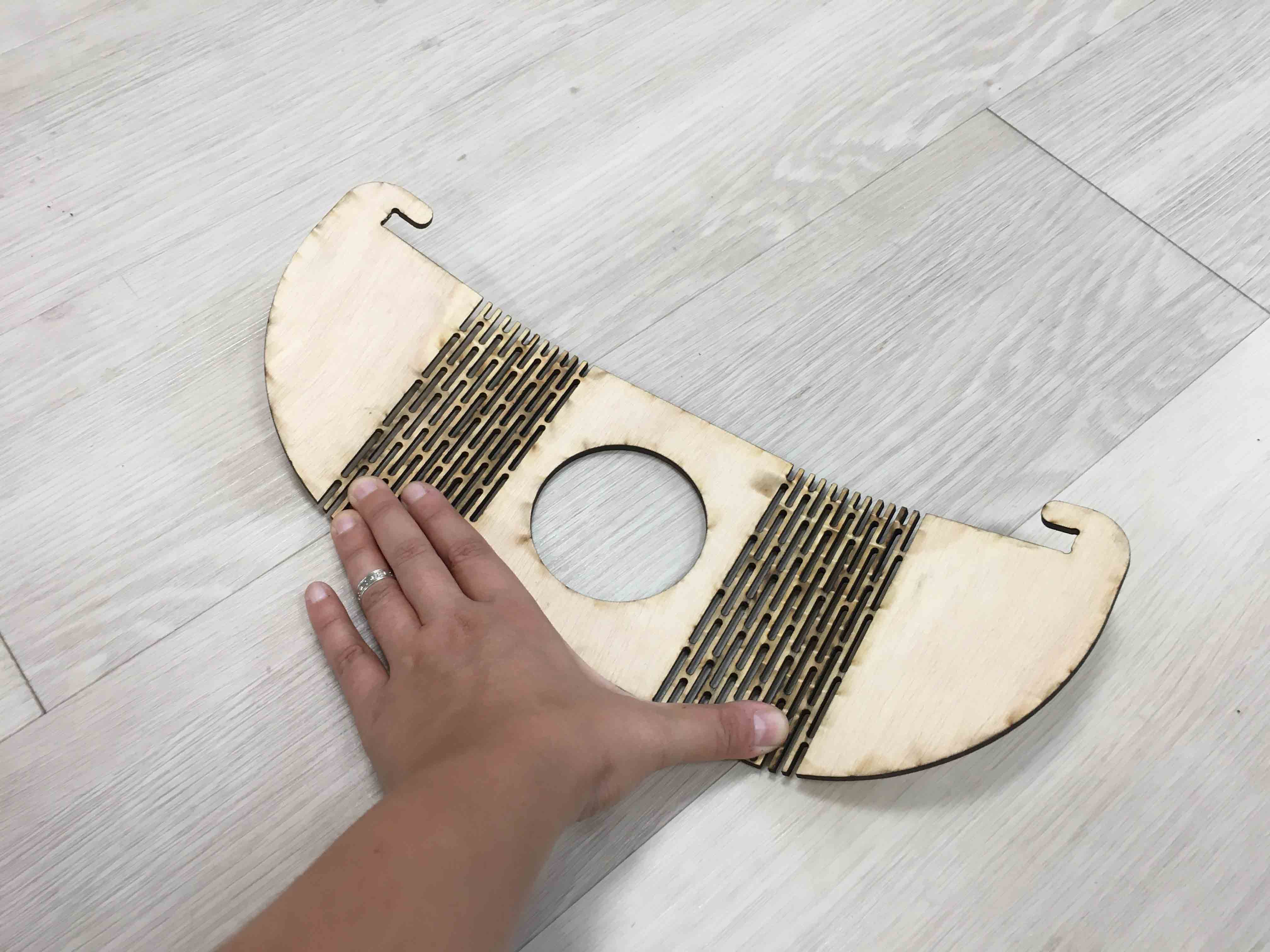
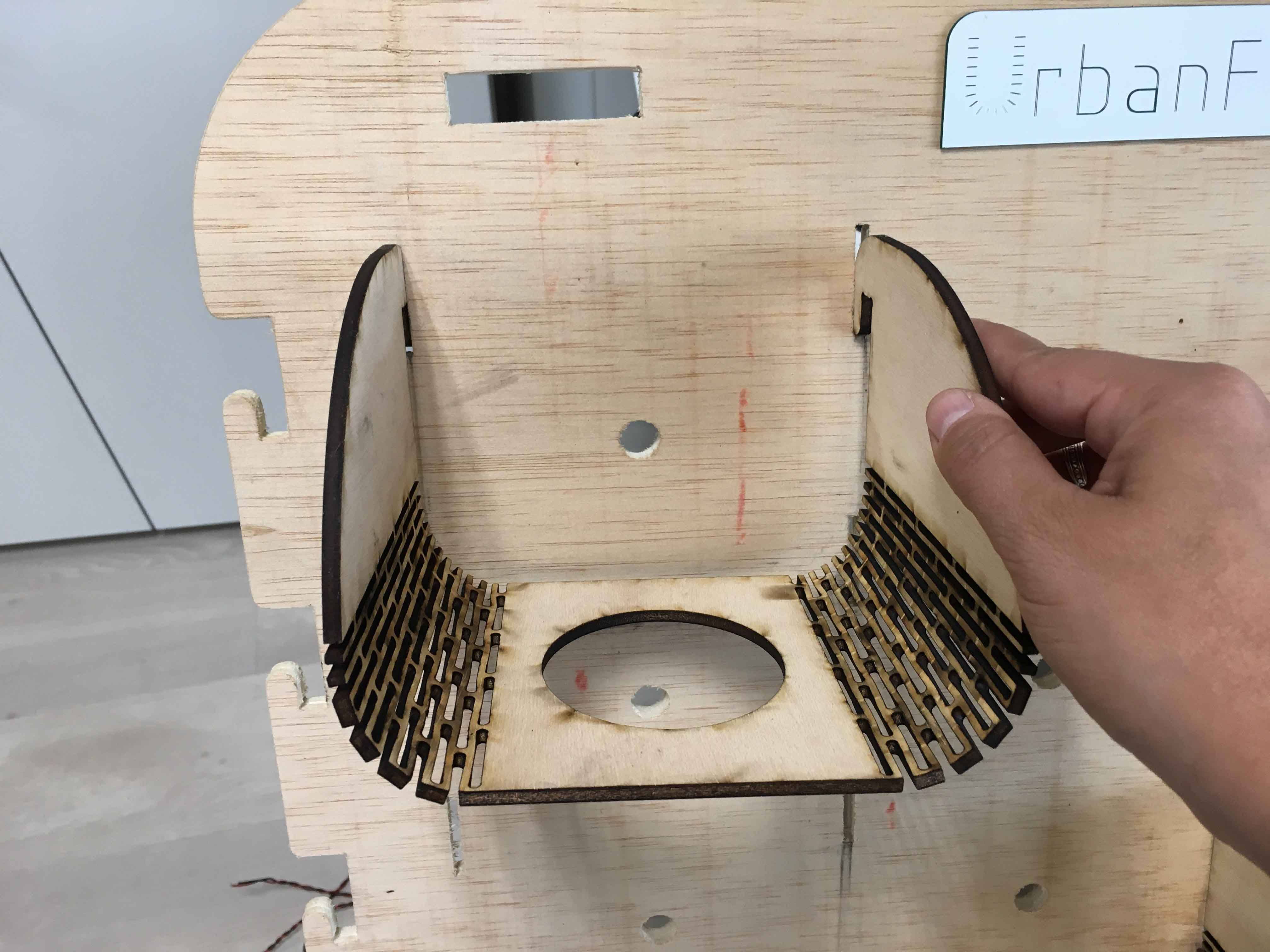
And as you can see below, it has been machined as in the Exercise 08. Computer Controlled Machining:
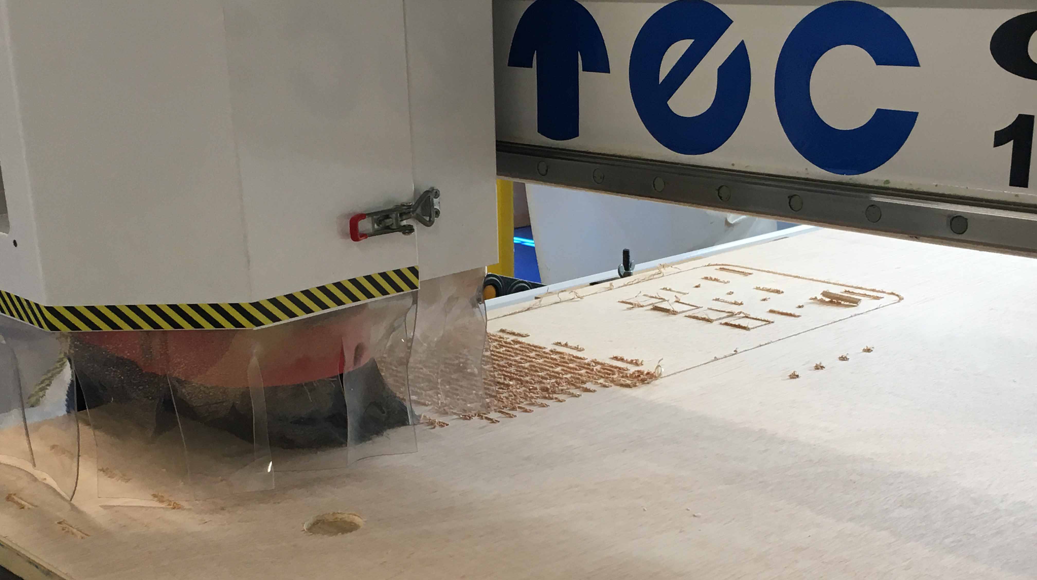
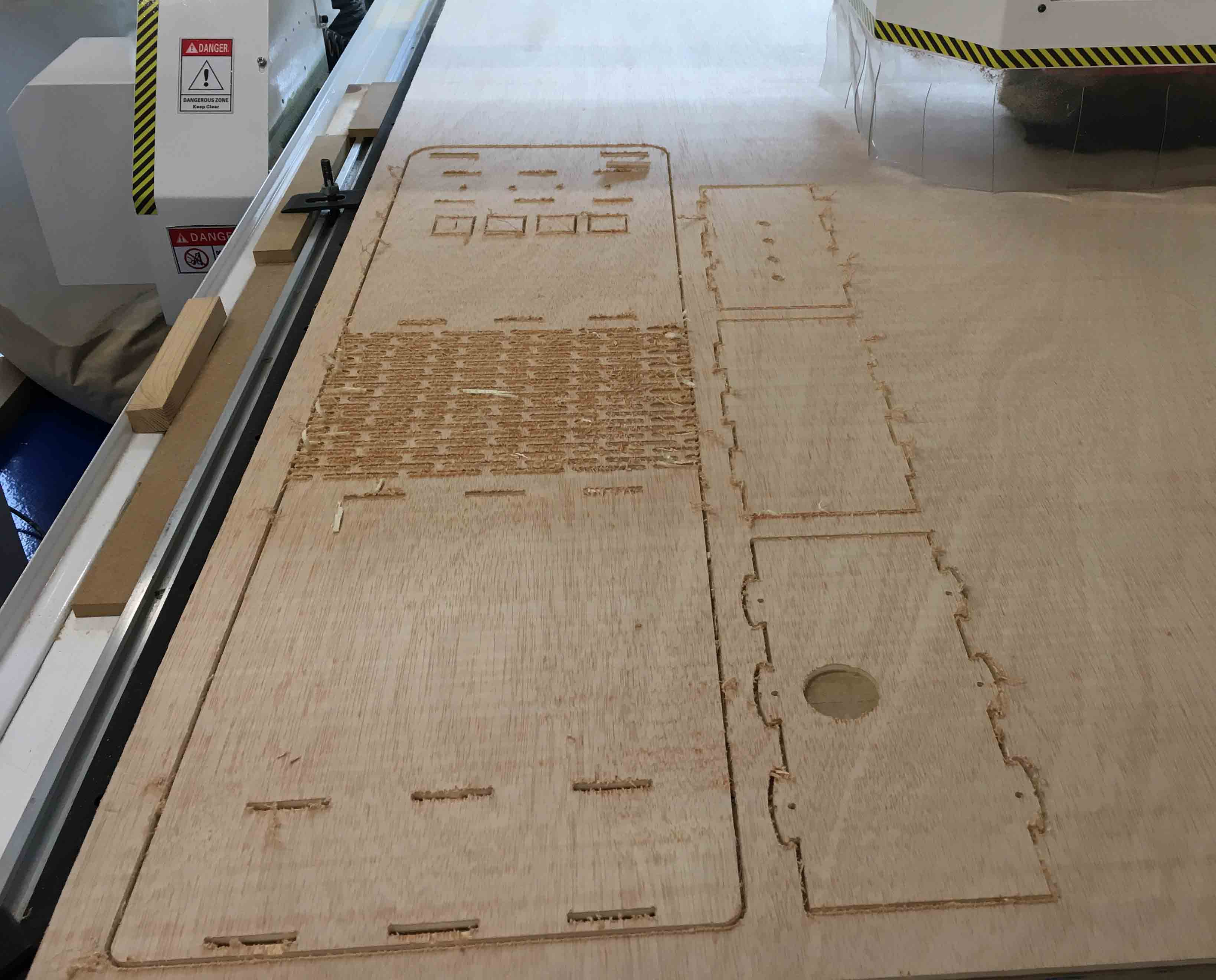
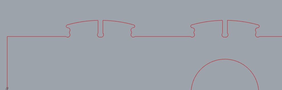
In this case I have used a new joint which has gone fine! :)
2_FLOWER-POT
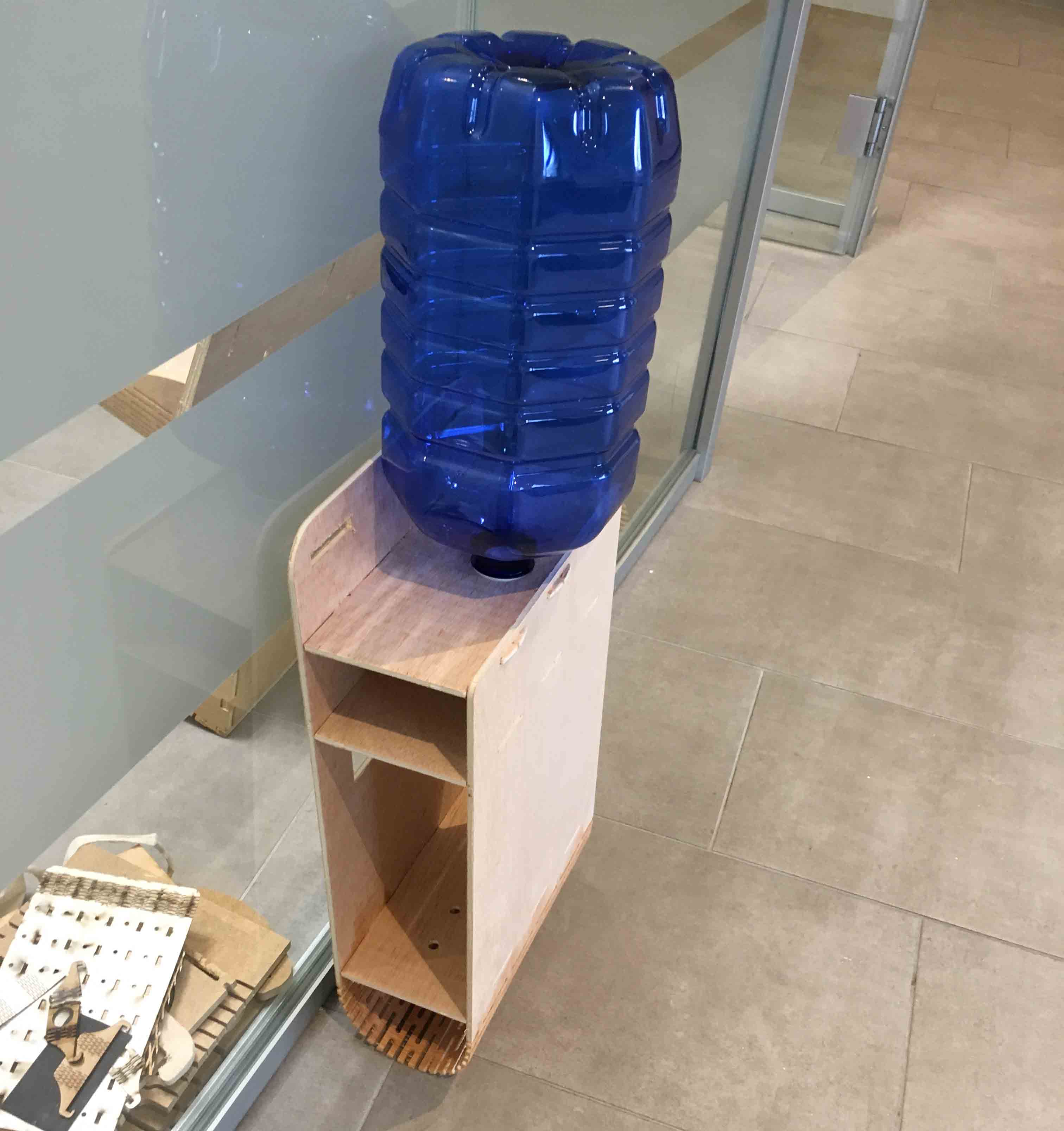
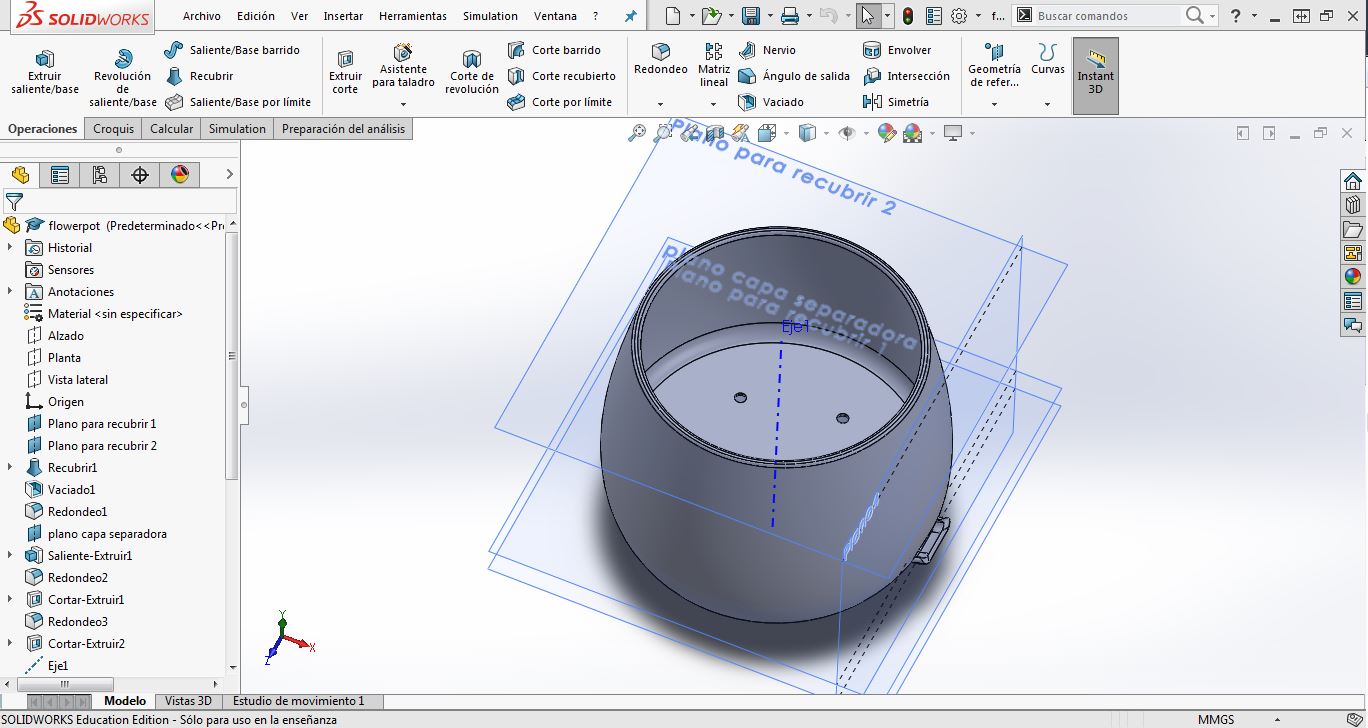
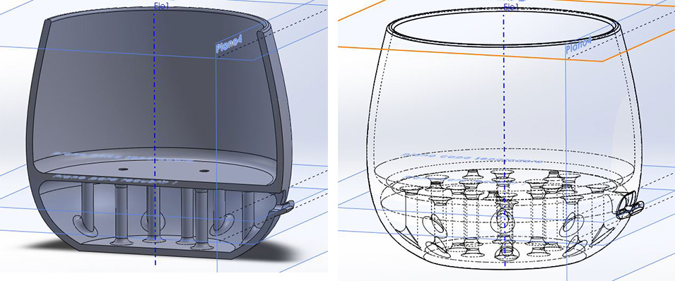
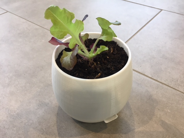
During Exercise 06. 3D scanning and Printing; I designed in 3D and printed a self-watered small flower-pot, for those plants which need less watering. It is a design with a water tank on its bottom: the plant stretches the roots down, and self-supplies water as needed.
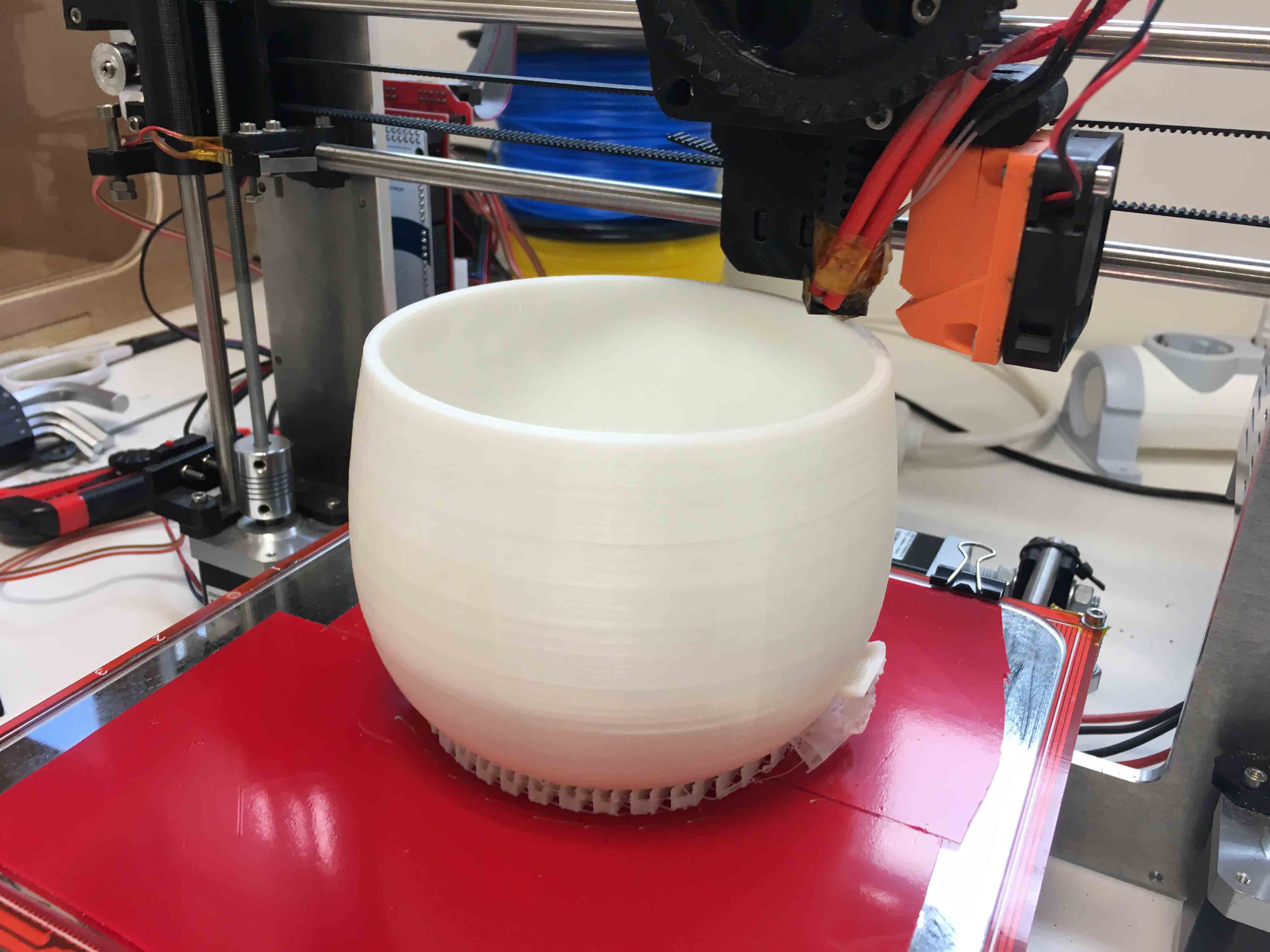
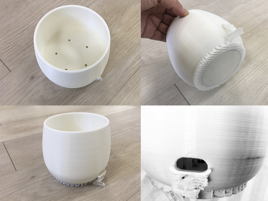
I've tried it during these 4 months (since February), and it works perfectly.
3_MAIN PCB
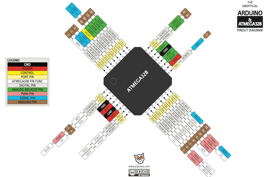
First of all, following my concpt I explained in IDEA AND CONCEPT DEVELOPMENT, I made an scheme to understand what I needed MAIN-PCB to do. Basically, I was going to use an ATMega 328P-AU as micro-controller, and I needed it to connect with sensors, valves and the user interface. User interface would be a wireless connection and for it I would use an ESP Wifi-PCB which will be separated from this MAIN-PCB for simplifying PCB designs.
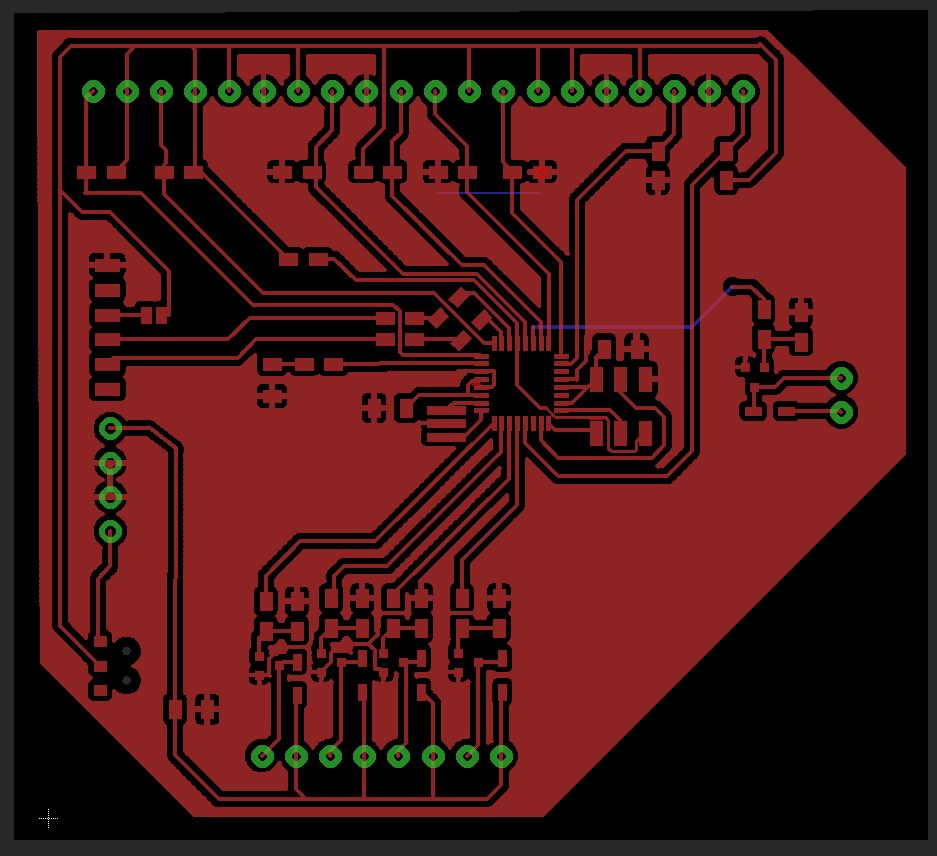
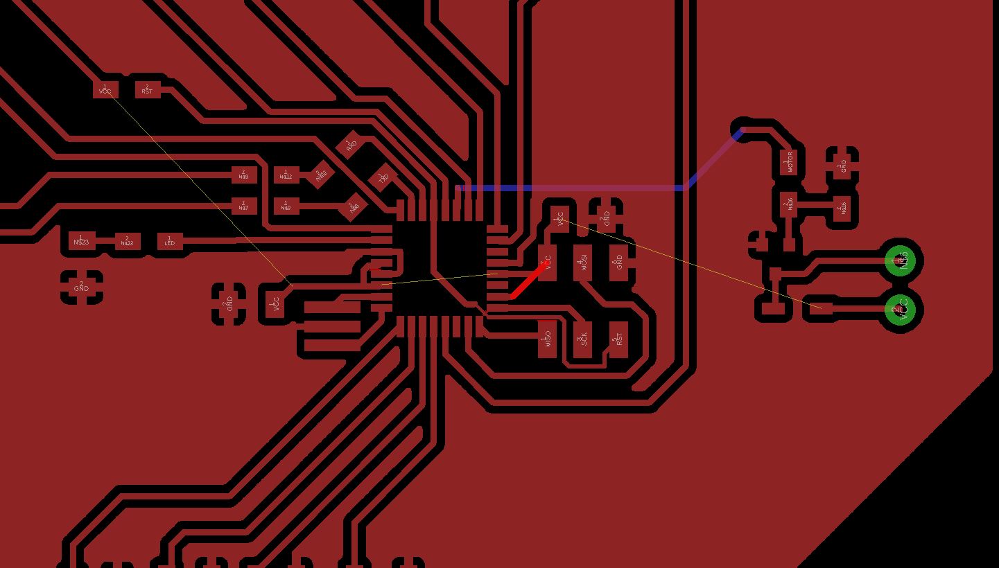
So I designed it on Eagle, as I did in previous assignments like Exercise 07. Electronics Design or Exercise 11. Input Devices. First of all I thought what I needed, I added all the elements on Eagle scheme and I connected everything. I have made some versions of it, first of get the final one which can be seen in the image below:
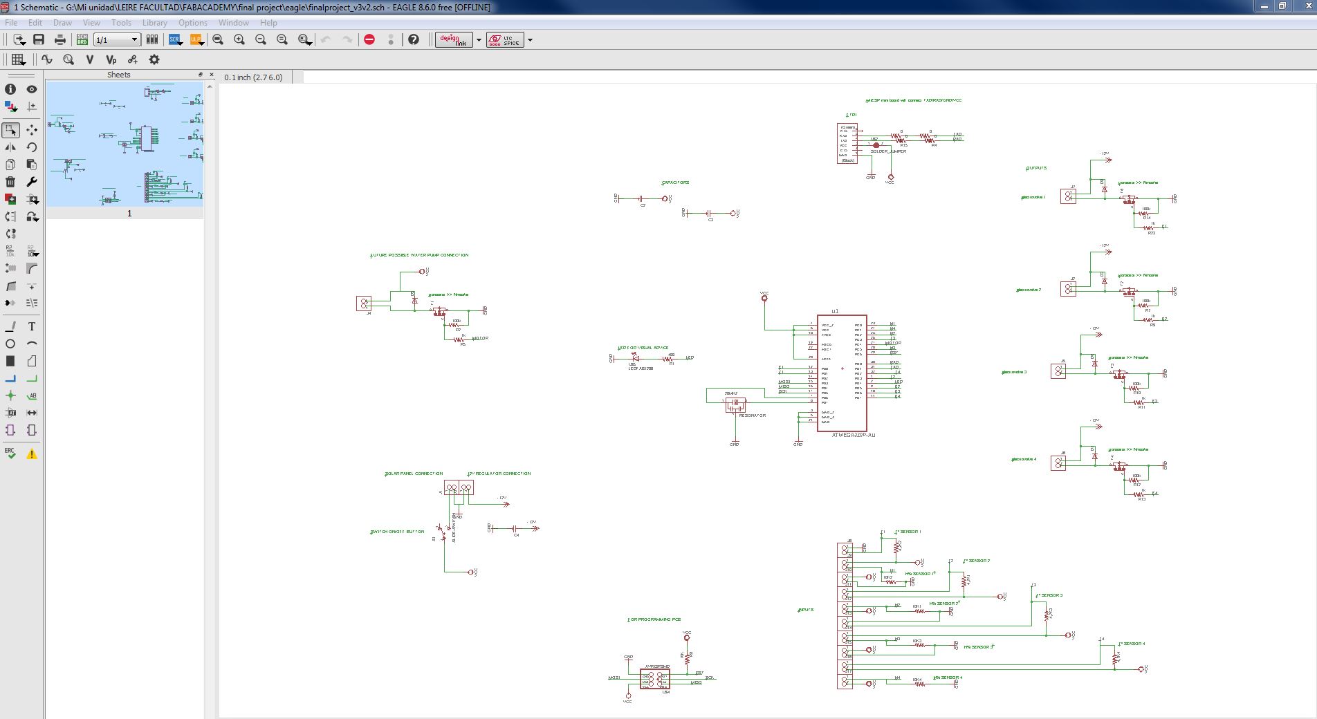
I have ordered them for each function and for a better understanding for me. :)
		_ Centered on working area ATMega328P-AU micro-controller.
		_ A led with its resistance.
		_ Capacitors for less "noise" in the circuit.
		_ FTDI for transmision and reception of DATA form ESP and for programming ATMega328P-AU, with a Jumper
		(unsoldered for programming, soldered to work with WIFI-BOARD connected)
		_ OUTPUTS: connections for each electro-valve. They need 12V each one, they need a Diode, each one, to
		ensure this 12V goes only in one way. They need also a mosfet each one as transistor for the difference
		between signal V and working V.
		_ INPUTS: connections to SOIL MOISTURE SENSORS and TEMPERATURE SENSORS, one for each.
		_ 2x3 AVRISP for connecting it to USBTinyISP.
		_ A solar panel connection, with a Switch ON/OFF button, for receiving power.
		_ A 12V regulator connection for sending needed power to Valves.
		*_ If someday I want to connect it to a water pump, a connection to it.
And taking in account ATMega328P-AU pins:
After having all components needed, I went to Eagle BOARD design tool, and I planned my MAIN_PCB. I was going crazy with connections, they were a lot, and imposible to make all them right without a lot of jumpers (I use 2 0Ohm resistors yet), so I decided to make GND to all PCB surface, and connect every GND to it. Still, I had to plan a couple of connections through the back, with cable.
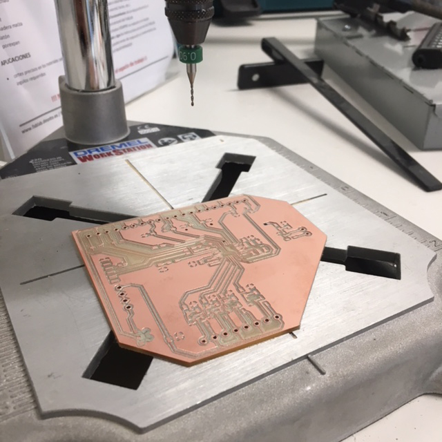
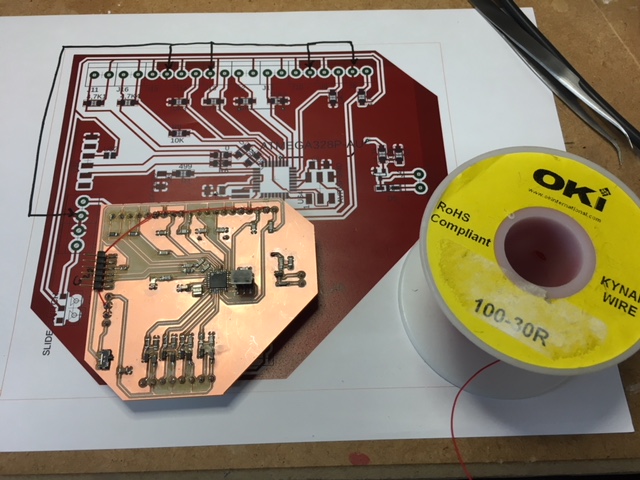
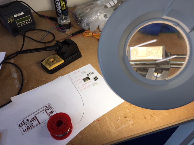
Once I had board design prepared, I exported BMP and I went to mill it, as I did in Exercise 07. Electronics Production first, and in Exercise 07. Electronics Design or Exercise 11. Input Devices later.
I had to make two milling attempts, I did not set the depth of the pass well the first time: I put 0.22 and the tracks were very thin, so I had to do it again:
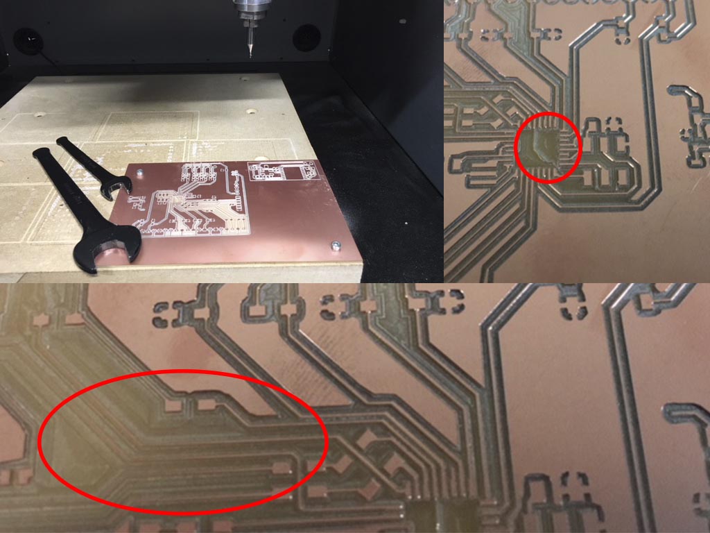
"nd attempt went well, so I made holes I needed to connect terminal blocks I had planned:
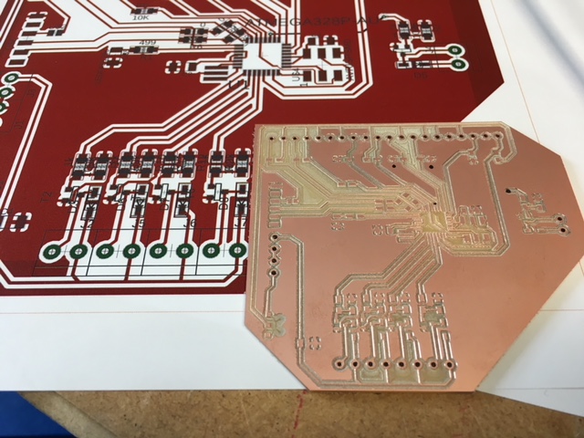
I made holes on it:
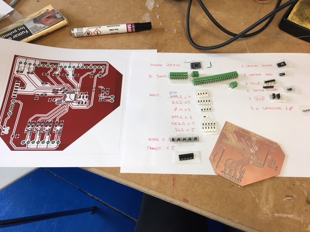
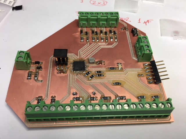
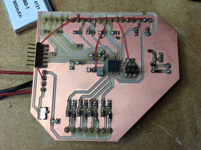
And I soldered every-component:
	_ ATMEGA 328P-AU, micro-controller
	_ 16 terminals blocks (2x16)
	_ RES-US1206FAB, RESISTORS: 4x4'99ohm, 5x10Kohm, 4x0ohm, 1x499ohm, 5x100Kohm, 5x1Kohm
	_ 5 DIODE
	_ 5 TRANSISTORS
	_ 1 RESONATOR, CRYSTAL 20MHz
	_ 1 LEDFAB RED
	_ 1 FTDI-SMD-HEADER, 6-pin header
	_ 1 SWITCH BUTTON
	_ 1 AVRISPSMD, 2x3 header
	_ 3 CAP UNPOLARIZEDFAB 1uF
ERROR!It was the first time I was soldering terminal blocks, and I soldered them on the wrong side. On this way it is imposible to have good connections.
*You can see here below a detail about other side cable conncetions too:
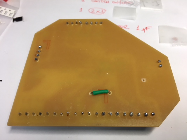
And ther was another ERROR too :S >> When I have been making Board design in Eagle, I hid VCC for visualizing better the other connections, and now, they were missing, I needed to connect some that were not.
NOW IT WAS PREPARED TO BE PROGRAMMED! :) You can find it in 5_PROGRAMMING.
4_WIFI PCB
I followed the same process as with the 3_MAIN PCB.
I milled it, toghether with MAIN-PCB, and I prepared components to be soldered:
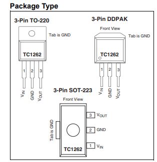
	_ 2 CAP UNPOLARIZEDFAB 1uF
	_ 2 SWITCH-6MM, button
	_ 1 ESP8266 Wi-Fi microchip
	_ 1 regulator TC1262
	_ 1 FTDI-SMD-HEADER, 6-pin header
	_ RES-US1206FAB, RESISTORS: 4x10Kohm
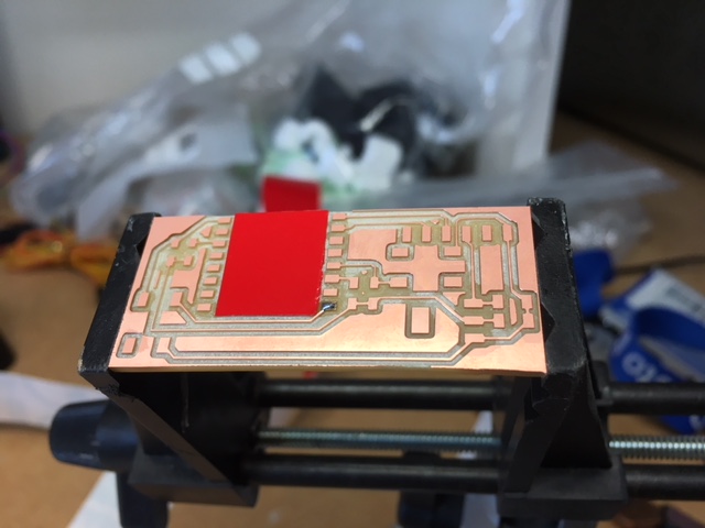
As I had problems soldering it in Exercise 14. networking and communications, in this case I decided to add an adhesive vinyl piece, to avoid unwanted connections under de ESP.
I soldered it, and this was the result:
But...PROBLEMS!! I looked a wrong TC1262 regulator pins scheme, and when I only connect it to my computer smoke came out and I was scared! I review everything and yes, the problem was the regulator.
I desoldered it, and then, I redesign WIFI-PCB changing these connections, milled it and soldered it again.
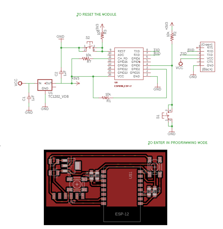
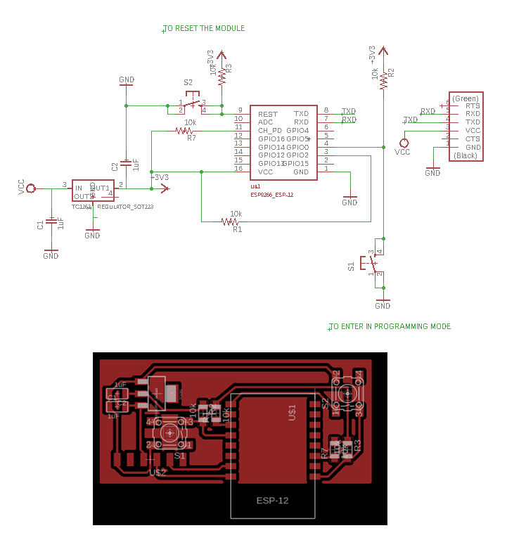
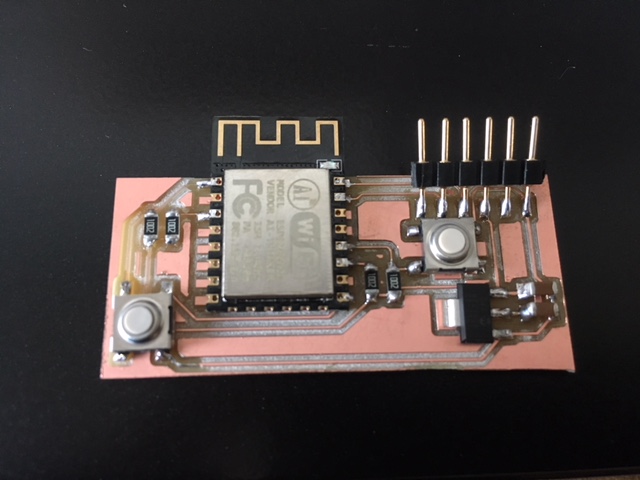
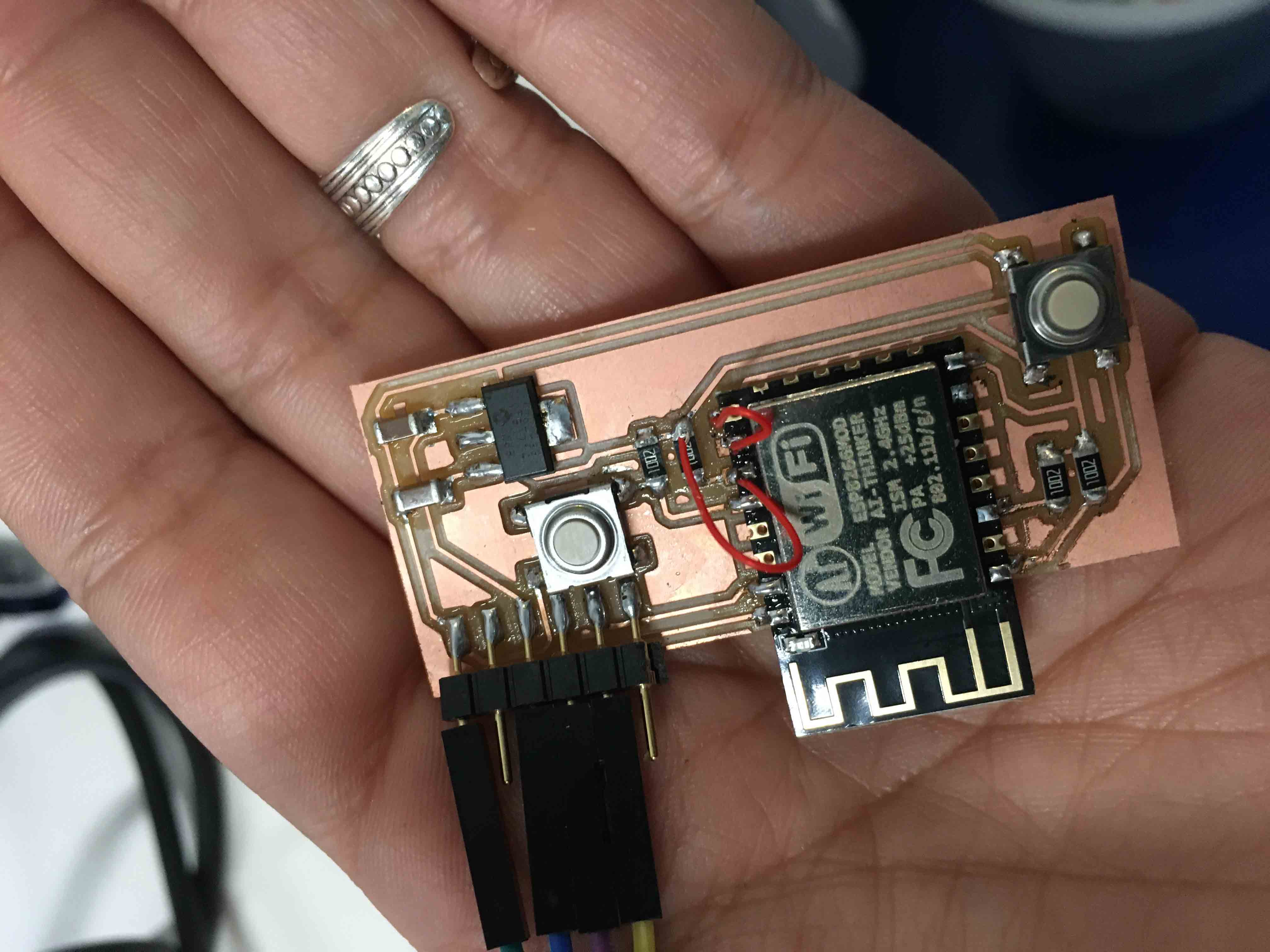
You can see the final WIFI-PCB in the image below: (red cables are due to a problem I have founded later, loading Firmware on it, in 5_PROGRAMMING area)
5_PROGRAMMING
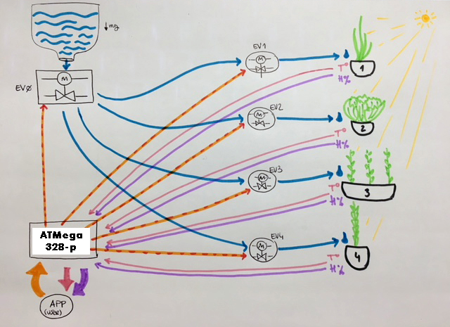
I have visualized all connections I needed doing the next scheme.
What I wanted my project to do was the following: Take info about each plant (humidity and temperature), communicate it to the user (who could be wherever he/she want) and if user sees that a plant needs to be watered, this action signal has to do the opposite way till the irrigation system of plants.
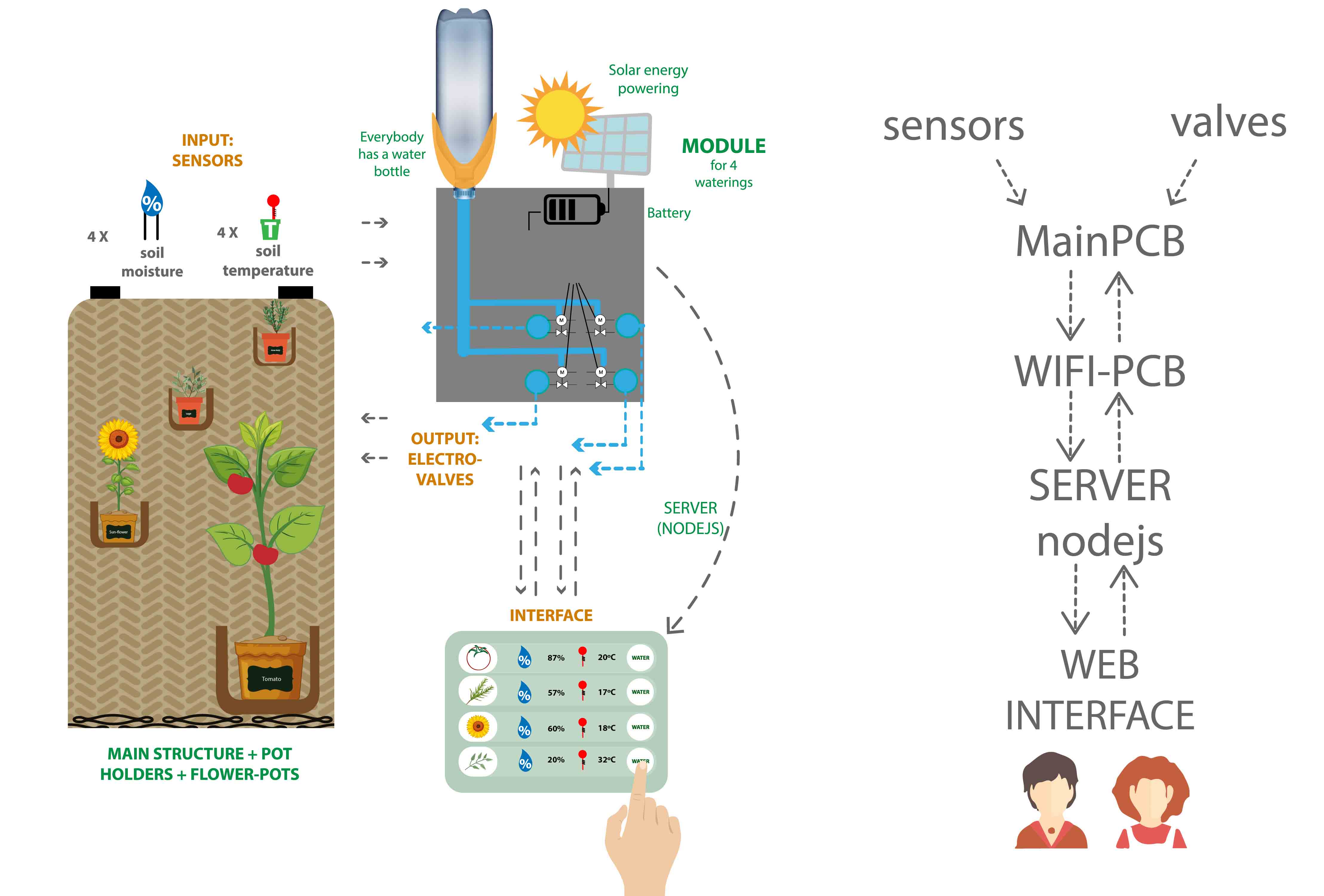
So I informed myself what I needed to do all these wired and wireless connections and, as you can see in the scheme, first I realized has been that I needed an always switched on computer at home, or a server. It is for managing all Data from my plants somewhere, to manage this wireless connection I have thought to do by Wifi signal.
I do not like to leave my personal computer always ON (when I am going to work or on holydays), so I have asked for a server here, in Deusto University, and I've got a server with a free DNS that is urbanflexipot.mooo.com. Servers are always switched ON into the university, so perfect!
NODEJS: SERVER and INTERFACE
As in Exercise 13. Interface and applications communication I used NODEJS to have this data sending, in both ways.
For doing it, I took node.js JSScript file, and I modified it (using Notepad++). I used JSON code as data exchange format. It uses human-readable text to transmit data objects consisting of attribute–value pairs and array data types (or any other serializable value). It is a very common data format used for asynchronous browser–server communication, so I changed code using an array, which takes 4 positions, one for each plant (plant[0], plant[1], plant[2], plant[3]), and writes it in JSON code mode using JSON.stringify(plant), with humidity and temperature parameters, and sends another data exchange using JSON.stringify(valve) to saying which valve needs to be opened to water one or the other plant.

Then, as you can see in code below, I used eval to convert this data structure in objects (and make the translate to my 7_USER INTERFACE).
You can see NODEJS: server.js CODE here below, and it can be found in Downloads area, on the botton of this site:
	var express = require('express'); //importa librería de express para crear servidores web
var app = express(); //crea una aplicación de express

app.use(express.static('public')); //le dice la carpeta donde está el contenido estatico, en mi caso fotos

app.get('/', function (req, res) {
   res.redirect('/final_interface.html');
})

app.get('/sensor', function (req, res) {
   res.send(JSON.stringify(plant));
})

app.get('/sendData', function (req, res) {
	var answer="";
	plant[0].humidity=req.param("hum0");
	plant[1].humidity=req.param("hum1");
	plant[2].humidity=req.param("hum2");
	plant[3].humidity=req.param("hum3");
	plant[0].temp=req.param("temp0");
	plant[1].temp=req.param("temp1");
	plant[2].temp=req.param("temp2");
	plant[3].temp=req.param("temp3");
	if (valve[0]==1){
		answer="0,"+waterinInterval;
		valve[0]=0;
	} else if (valve[1]==1){
		answer="1,"+waterinInterval;
		valve[1]=0;
	} else if (valve[2]==1){
		answer="2,"+waterinInterval;
		valve[2]=0;
	} else if (valve[3]==1){
		answer="3,"+waterinInterval;
		valve[3]=0;
	}
   res.send(answer);
})

app.get('/regar', function (req, res) {
	num=eval (req.param("valve"));
	valve[num]=1;
	console.log(JSON.stringify(valve));
   res.send("regando");

})

var server = app.listen(8081, function () {
   var host = server.address().address
   var port = server.address().port

   console.log("Example app listening at http://%s:%s", host, port)

})

var plant = new Array();
plant[0]=new Object();
plant[0].temp=0;
plant[0].humidity=0;

plant[1]=new Object();
plant[1].temp=0;
plant[1].humidity=1;

plant[2]=new Object();
plant[2].temp=0;
plant[2].humidity=2;

plant[3]=new Object();
plant[3].temp=0;
plant[3].humidity=1;

var dato=0;

var valve = new Array();
valve[0]=0;
valve[1]=0;
valve[2]=0;
valve[3]=0;

var waterinInterval=10000;
And then, I have modified final_interface.html from Exercise 13. Interface and applications communication too, to have graphics and actions for 4 plants.
I could have done it with a for command, but I prefered to write it using if from each plant humidity and temperature, due to its simplicity on reading and understanding (and my programming low knowledge :) ). As I commented before, I used eval to convert JSON data structure in objects.
You can see NODEJS: final_interface.html CODE here below, and it can be found in Downloads area, on the botton of this site:
<!DOCTYPE html>
<html lang="en">
<head>
<meta name="viewport" content="width=device-width, initial-scale=1">
  <link rel="stylesheet" href="https://maxcdn.bootstrapcdn.com/bootstrap/3.3.7/css/bootstrap.min.css">
  <script src="https://ajax.googleapis.com/ajax/libs/jquery/3.3.1/jquery.min.js"></script>
  <script src="https://maxcdn.bootstrapcdn.com/bootstrap/3.3.7/js/bootstrap.min.js"></script>
    <meta charset="utf-8">
    <meta http-equiv="X-UA-Compatible" content="IE=edge">
    <meta name="viewport" content="width=device-width, initial-scale=1">
    <meta name="description" content="">
    <meta name="author" content="Name Surname">
	<style>
	.celdas {
		float: left;
		width : 20%;
	}
	span {
		position: relative;
    left: 10px;
    top: 1em;
	font-size : 3em;
	}
	.contenedor{
	position: relative;
    display: inline-block;
    text-align: center;
	}

	.texto-encima{
    position: absolute;
    top: 50%;
    left: 60%;
	}
	.centrado{
    display: table-cell;
    vertical-align: middle;
	}

	</style>

	<script>

	setInterval(estado,1000); //read Status every 1 second

	function estado(){ //Status function; how is the humidity?
		var req=new XMLHttpRequest(); //HTTP defines a set of request methods to indicate the desired action to be performed for a given resource.
		req.open('GET','sensor',true); //GET request method: The GET method requests a representation of the specified resource ("sensor").
		//Requests using GET should only retrieve data.
		req.onreadystatechange=function (aEvt){
			if (req.readyState==4){
				if (req.status==200){
					procesarDatos(req.responseText);
				}
			}
		};
		req.send(null); //If the request method is GET, the body parameter is ignored and request body is set to null.

	}
	function regar(num){
		var req2=new XMLHttpRequest();
		req2.open('GET','regar?valve='+num,true);
		req2.onreadystatechange=function (aEvt){
			if (req2.readyState==4){
				if (req2.status==200){

				}
			}
		};
		req2.send(null);
	}

	function procesarDatos(texto){
	datos=eval(texto);
		document.getElementById("temp0").innerHTML=datos[0].temp+"ºC";
		document.getElementById("temp1").innerHTML=datos[1].temp+"ºC";
		document.getElementById("temp2").innerHTML=datos[2].temp+"ºC";
		document.getElementById("temp3").innerHTML=datos[3].temp+"ºC";

		if (datos[0].humidity==0){ //Happy flower if signal "0"
				document.getElementById("foto0").src="media/humidity1.png";
			}
		if (datos[0].humidity==1){ //Worried flower if signal "1"
				document.getElementById("foto0").src="media/humidity2.png";
			}
		if (datos[0].humidity==2){ //Sad flower if signal "2"
				document.getElementById("foto0").src="media/humidity3.png";
			}

		if (datos[1].humidity==0){ //Happy flower if signal "0"
				document.getElementById("foto1").src="media/humidity1.png";
			}
		if (datos[1].humidity==1){ //Worried flower if signal "1"
				document.getElementById("foto1").src="media/humidity2.png";
			}
		if (datos[1].humidity==2){ //Sad flower if signal "2"
				document.getElementById("foto1").src="media/humidity3.png";
			}

		if (datos[2].humidity==0){ //Happy flower if signal "0"
				document.getElementById("foto2").src="media/humidity1.png";
			}
		if (datos[2].humidity==1){ //Worried flower if signal "1"
				document.getElementById("foto2").src="media/humidity2.png";
			}
		if (datos[2].humidity==2){ //Sad flower if signal "2"
				document.getElementById("foto2").src="media/humidity3.png";
			}
		if (datos[3].humidity==0){ //Happy flower if signal "0"
				document.getElementById("foto3").src="media/humidity1.png";
			}
		if (datos[3].humidity==1){ //Worried flower if signal "1"
				document.getElementById("foto3").src="media/humidity2.png";
			}
		if (datos[3].humidity==2){ //Sad flower if signal "2"
				document.getElementById("foto3").src="media/humidity3.png";
			}
	}


	</script>
</head>
<body >

<div id="header">
<img src="media/logo.jpg" width="100%">
</div>

<div id="content"  style="background-color:#e6e6e6" style="width:100%; min-height: 50px;">

<div id="fila1" class="row" style="border-style:solid">
<div class="col-sm-2" ><img src="media/plant1.png" width="100%"></div>
<div class="col-sm-2"  ><img id="foto0" src="media/humidity1.png" width="100%"></div>
<div  class="col-sm-2" ><img  src="media/temperature.png" width="100%" ></div>
<div class="col-sm-2"><div ><span id="temp0">20</span></div></div>
<div  class="col-sm-2"><img onclick="regar(0)" src="media/water1.png" width="100%"> </div>
</div>

<div id="fila2" class="row" style="border-style:solid">
<div class="col-sm-2" ><img src="media/plant2.png" width="100%"></div>
<div class="col-sm-2"  ><img id="foto1" src="media/humidity1.png" width="100%"></div>
<div  class="col-sm-2" ><img  src="media/temperature.png" width="100%" ></div>
<div class="col-sm-2"><div ><span id="temp1">20</span></div></div>
<div  class="col-sm-2"><img onclick="regar(1)" src="media/water2.png" width="100%"> </div>
</div>


<div id="fila3" class="row" style="border-style:solid">
<div class="col-sm-2" ><img src="media/plant3.png" width="100%"></div>
<div class="col-sm-2"  ><img id="foto2" src="media/humidity1.png" width="100%"></div>
<div  class="col-sm-2" ><img  src="media/temperature.png" width="100%" ></div>
<div class="col-sm-2"><div ><span id="temp2">20</span></div></div>
<div  class="col-sm-2"><img onclick="regar(2)" src="media/water3.png" width="100%"> </div>
</div>


<div id="fila4" class="row" style="border-style:solid">
<div class="col-sm-2" ><img src="media/plant4.png" width="100%"></div>
<div class="col-sm-2"  ><img id="foto3" src="media/humidity1.png" width="100%"></div>
<div  class="col-sm-2" ><img  src="media/temperature.png" width="100%" ></div>
<div class="col-sm-2"><div ><span id="temp3">20</span></div></div>
<div  class="col-sm-2"><img onclick="regar(3)" src="media/water4.png" width="100%"> </div>
</div>

</div>

</body>
</html>
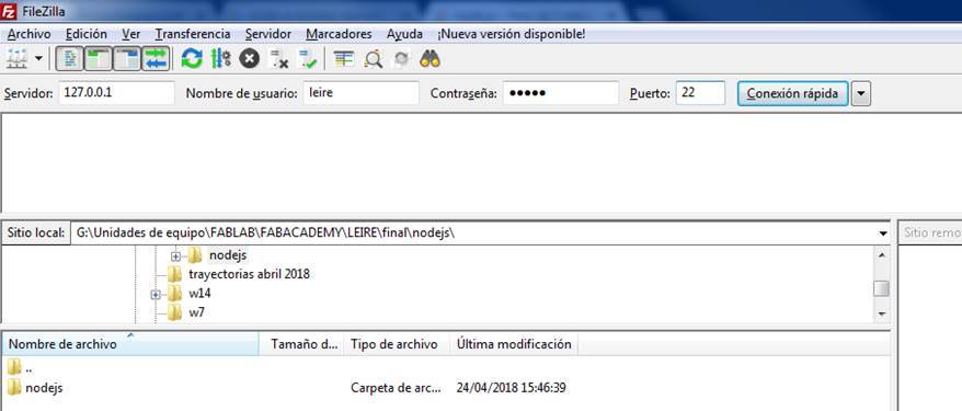
In NODEJS folder, as you can see if you download NODEJS file for server and interface, there is everything about these two precedent codes, all png images created also for visual graphics of the interface are inside. So it has to be uploaded everything, whole folder, to the server, to make them work.
I have used Filezilla, a free FTP solution for both client and server, to upload it to the server. It is very simple to use, you have only to choose folder you want to upload to the server and say to upload it:
ARDUINO: MAIN PCB PROGRAMMING
You can see here below the code for programming my 3_MAIN PCB.
As in precedent exercises during FabAcademy assignments, I used Arduino programming language due to its simplicity, and also because exists a lot of information about it in internet. Programming has been the most difficult phase during FabAcademy, I am industrial designer, so I'm closer to more mechanical technologies nad not to these electronics programming magic ones! :)
There are a pair of details to be explained here:
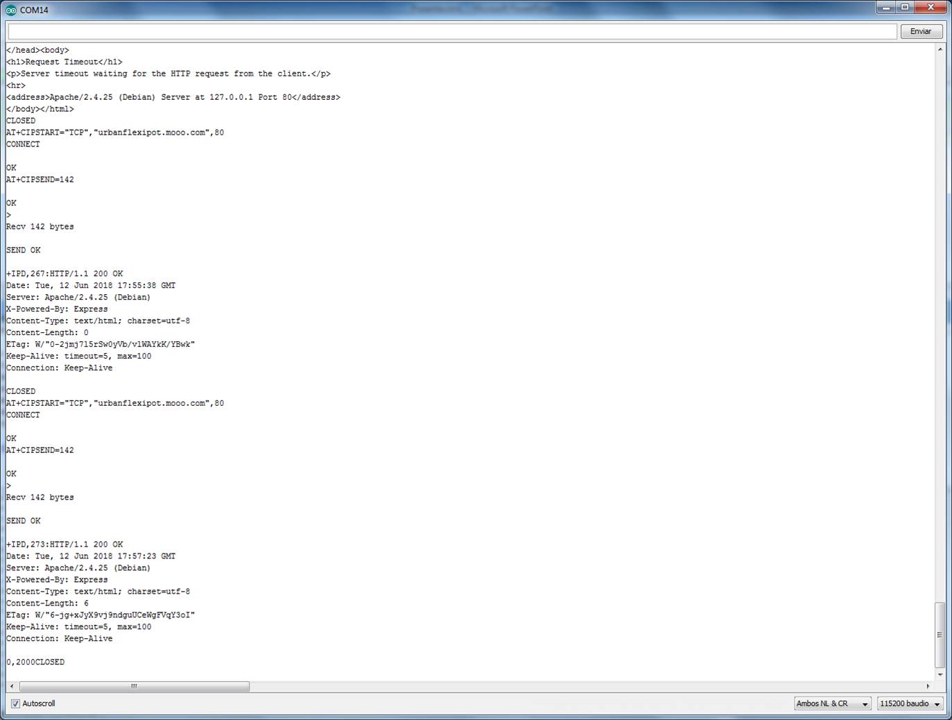
_ When I use if (content.indexOf("leire") > 2): it is because when I saw how was RXD (reception) and TXD(transmision)
of the ESP 4_WIFI PCB, I needed something to MAIN-PCB reading the line where it sends the signal to
watering one or the other plant. See image below:
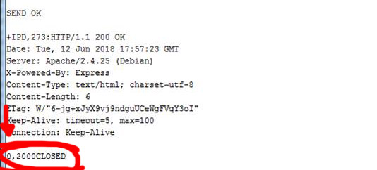 I needed to extract the 1st character of the line: first of all I changed "CLOSED" for "leire", and with (content.indexOf("leire") > 2)
I am saying to find a line where it is writen "leire" after the first 2 characters of this line. When it finds it, this code reads the first
character, which is linked to the plant I need to water.
_ I had problems with delays and actions it took at the same time, so I created another VOID to sending data from sensors, and I added
it in VOID LOOP as the first action to do, and then after that to run "regar" (watering) action if it is asked. It was as if it were
entering a loop and could not exit. I have been testing with delays too, because there was one (on the bottom) which was slowing down
signal and sends of data.
I needed to extract the 1st character of the line: first of all I changed "CLOSED" for "leire", and with (content.indexOf("leire") > 2)
I am saying to find a line where it is writen "leire" after the first 2 characters of this line. When it finds it, this code reads the first
character, which is linked to the plant I need to water.
_ I had problems with delays and actions it took at the same time, so I created another VOID to sending data from sensors, and I added
it in VOID LOOP as the first action to do, and then after that to run "regar" (watering) action if it is asked. It was as if it were
entering a loop and could not exit. I have been testing with delays too, because there was one (on the bottom) which was slowing down
signal and sends of data.
You can see ARDUINO CODE FOR MAIN PCB here below, and it can be found in Downloads area, on the botton of this site:
#include// to humidity sensors #include // to temperature sensors OneWire wirePlant0(9); //pin 9 is bus OneWire in plant 1 OneWire wirePlant1(3); //pin 3 is bus OneWire in plant 2 OneWire wirePlant2(A3); //pin A3 is bus OneWire in plant 3 OneWire wirePlant3(2); //pin 2 is bus OneWire in plant 4 DallasTemperature tempPlant0(&wirePlant0); //variable or object to temperature sensor in plant 1 DallasTemperature tempPlant1(&wirePlant1); //variable or object to temperature sensor in plant 2 DallasTemperature tempPlant2(&wirePlant2); //variable or object to temperature sensor in plant 3 DallasTemperature tempPlant3(&wirePlant3); //variable or object to temperature sensor in plant 4 unsigned long currentTime ; unsigned long previousTime = 0; int humidity0 = 0; int h0 = 0; int h0dato = 0; int humidity1 = 0; int h1 = 0; int h1dato = 0; int humidity2 = 0; int h2 = 0; int h2dato = 0; int humidity3 = 0; int h3 = 0; int h3dato = 0; int temp0; int temp1; int temp2; int temp3; int pinLed = 4; String content = ""; int valv0 = 8; int valv1 = 5; int valv2 = 6; int valv3 = 7; void setup() { // put your setup code here, to run once: Serial.begin(115200); tempPlant0.begin(); //Se inicia el sensor tempPlant1.begin(); //Se inicia el sensor tempPlant2.begin(); //Se inicia el sensor tempPlant3.begin(); //Se inicia el sensor pinMode(pinLed, OUTPUT); pinMode(valv0, OUTPUT); pinMode(valv1, OUTPUT); pinMode(valv2, OUTPUT); pinMode(valv3, OUTPUT); digitalWrite (valv0, LOW); digitalWrite (valv1, LOW); digitalWrite (valv2, LOW); digitalWrite (valv3, LOW); digitalWrite(pinLed, LOW); delay(1000); } void loop() { sendData (); //REGAR String content = Serial.readStringUntil('\n'); if (content.indexOf("leire") > 2) { Serial.println("Detected"); int valve = content.charAt(0) - 48; digitalWrite(pinLed, HIGH); if (valve == 0) { digitalWrite(valv0, HIGH); delay(10000); digitalWrite(valv0, LOW); } if (valve == 1) { digitalWrite(valv1, HIGH); delay(10000); digitalWrite(valv1, LOW); } if (valve == 2) { digitalWrite(valv2, HIGH); delay(10000); digitalWrite(valv2, LOW); } if (valve == 3) { digitalWrite(valv3, HIGH); delay(10000); digitalWrite(valv3, LOW); } digitalWrite(pinLed, LOW); } } void sendData () { // put your main code here, to run repeatedly: currentTime = millis(); if (currentTime - previousTime > 10000) { previousTime = currentTime; humidity0 = analogRead(A0); //humidity sensor read a number h0 = (int)((humidity0 * 10) / 78); // we need to make a percent, and logical operation would be data*100/780 if ((h0 < 70) && (h0 > 40)) { h0dato = 1; //Sends a "1" signal, plant humidity is MORE OR LESS OK } else { if (h0 < 40) { h0dato = 2; //Sends a "2", plant humidity is NOT OK } else { h0dato = 0; //Sends a "0", plant humidity is OK } } humidity1 = analogRead(A2); //humidity sensor read h1 = (int)((humidity1 * 10) / 78); if ((h1 < 70) && (h1 > 40)) { h1dato = 1; } else { if (h1 < 40) { h1dato = 2; } else { h1dato = 0; } } humidity2 = analogRead(A5); //humidity sensor read h2 = (int)((humidity2 * 10) / 78); if ((h2 < 70) && (h2 > 40)) { h2dato = 1; } else { if (h2 < 40) { h2dato = 2; } else { h2dato = 0; } } humidity3 = analogRead(A1); //humidity sensor read h3 = (int)((humidity3 * 10) / 78); if ((h3 < 70) && (h3 > 40)) { h3dato = 1; } else { if (h3 < 40) { h3dato = 2; } else { h3dato = 0; } } tempPlant0.requestTemperatures(); //It sends temperature command to read data temp0 = tempPlant0.getTempCByIndex(0); //it takes temperature in ºC tempPlant1.requestTemperatures(); temp1 = tempPlant1.getTempCByIndex(0); tempPlant2.requestTemperatures(); temp2 = tempPlant2.getTempCByIndex(0); tempPlant3.requestTemperatures(); temp3 = tempPlant3.getTempCByIndex(0); //SEND DATA FROM SENSORS char buffer[200] = " "; char* formato = "GET /sendData?temp0=%d&temp1=%d&temp2=%d&temp3=%d&hum0=%d&hum1=%d&hum2=%d&hum3=%d HTTP/1.1\r\nHost: urbanflexipot.mooo.com\r\nConnection: keep-alive\r\n\r\n"; sprintf(buffer, formato, temp0, temp1, temp2, temp3, h0dato, h1dato, h2dato, h3dato); Serial.print("AT+CIPSTART=\"TCP\",\"urbanflexipot.mooo.com\",80\r\n"); delay(1000); Serial.print("AT+CIPSEND="); Serial.println(strlen(buffer)); delay(1000); Serial.print(buffer); } }
For programming my MAIN-PCB with this code I used: First USBTinyISP made in Exercise 05. Electronics Production for BURN BOOTLOADER, and FTDI to LOAD code later.
ATENTION! to take in account: J1 jumper has to be unsoldered to program MAIN-PCB, see board-scheme in 3_MAIN PCB.
WIFI/ESP FIRMWARE AND COMMUNICATION
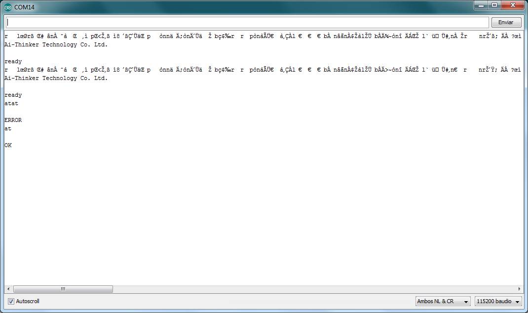
For WIFI_PCB first of all I needed to know if it had its firmware already inside, or not.
For it I connect 4_WIFI PCB to my computer with a USB-FTDI cable, and using Arduino's Serial Port I send an AT command to it. No answer! So it was no firmware into it.
You can see AT commands in this document which provides AT commands list based on ESP8266_NONOS_SDK, but there are a lot surfing internet. The AT Commands of the ESP8266 WiFi Module are responsible for controlling all the operations of the module like restart, connect to WiFi, change mode of operation and so forth.
But, to program my ESP with those AT commands, I needed first to load firmware into it.
I followed this tutorial on internet:
	_ Download ESP8266 DOWNLOAD TOOL and AT FIRMWARE needed.
		(You can find them in Download area on the botton of this site, as "ESP WIFI board FIRMWARE files".)
	_ Step 1: Install Flash Tool and First Run
	_ Step 2: First Connection to ESP82666: press START and on WIFI_PCB keep "FLASH botton" and, when the text window shows "Connecting...",
	quickly press and release "RESET button" while keeping the FLASH button pressed.
	_ Step 3: Flash AT Firmware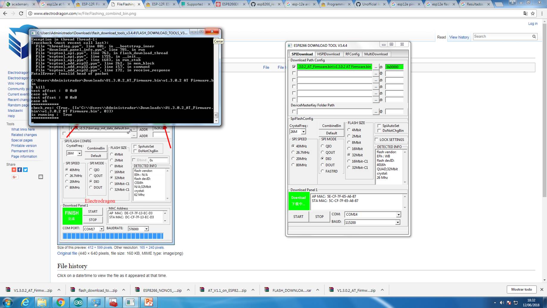
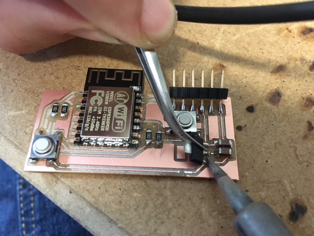
In the first attempt I had problems, WIFI_PCB was not connecting on this first connection. WHY??
I have forgotten these two connections (red wired) you can see in the image below. After that Firmware upload worked properly.
After that I programmed ESP using AT commands. Opened Serial Port viewer, and first of all I asked AT after adjusting it to 115200 baudios, and it answered OK! :)
I used this commands to program it, as you can see in the image below:
	_ AT+RST—Restarts the Module
	_ AT+CWLAP-Lists available APs
	_ AT+CWJAP_DEF-Connects to an AP; configuration saved in the flash
	_ AT+CIPSTART-Connects to an url, establishes TCP Connection, UDP Transmission or SSL Connection
	_ AT-CIPSEND=NUM-Sends Data >> Data from Server in JSON format
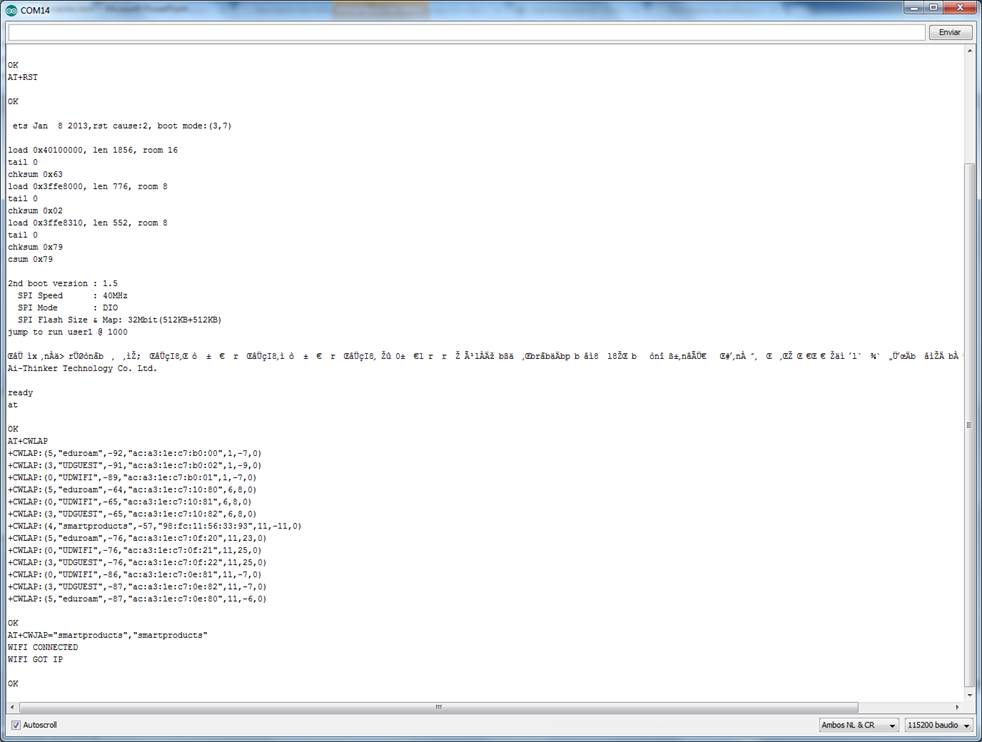
It has been difficult to understand how much characters I had to write when I AT-CIPSEND=NUM to send >GET /sendData?temp0=0&temp1=0&temp2=0&temp3=0&hum0=0&hum1=0&hum2=0&hum3=0 HTTP/1.1, but finally I hit the number 142. :D
And ESP WIFI-PCB was already to use!
6_INPUT AND OUTPUT DEVICES
For inputs and outputs I have used temperature digital sensors (bought, Ds18b20 temperature sensors), Humidity/soil moisture sensors (DIY) and 12V solenoid small valves (bought).
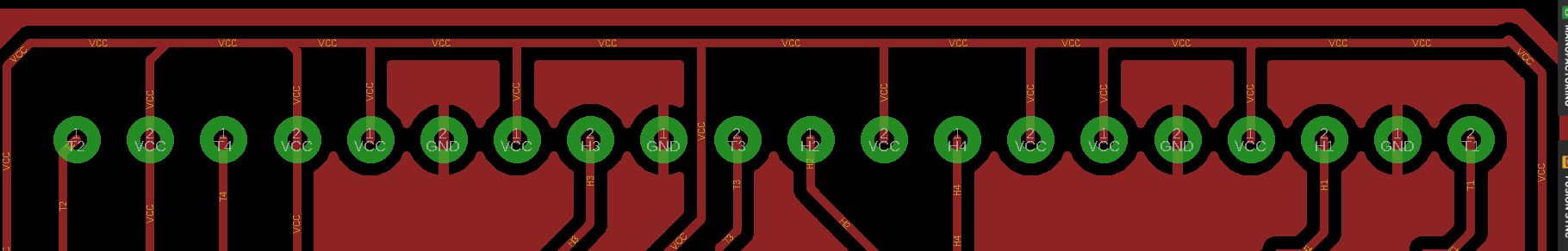
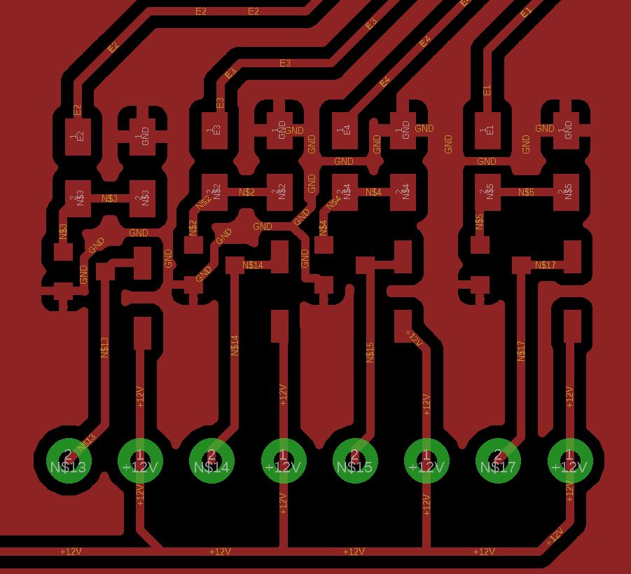
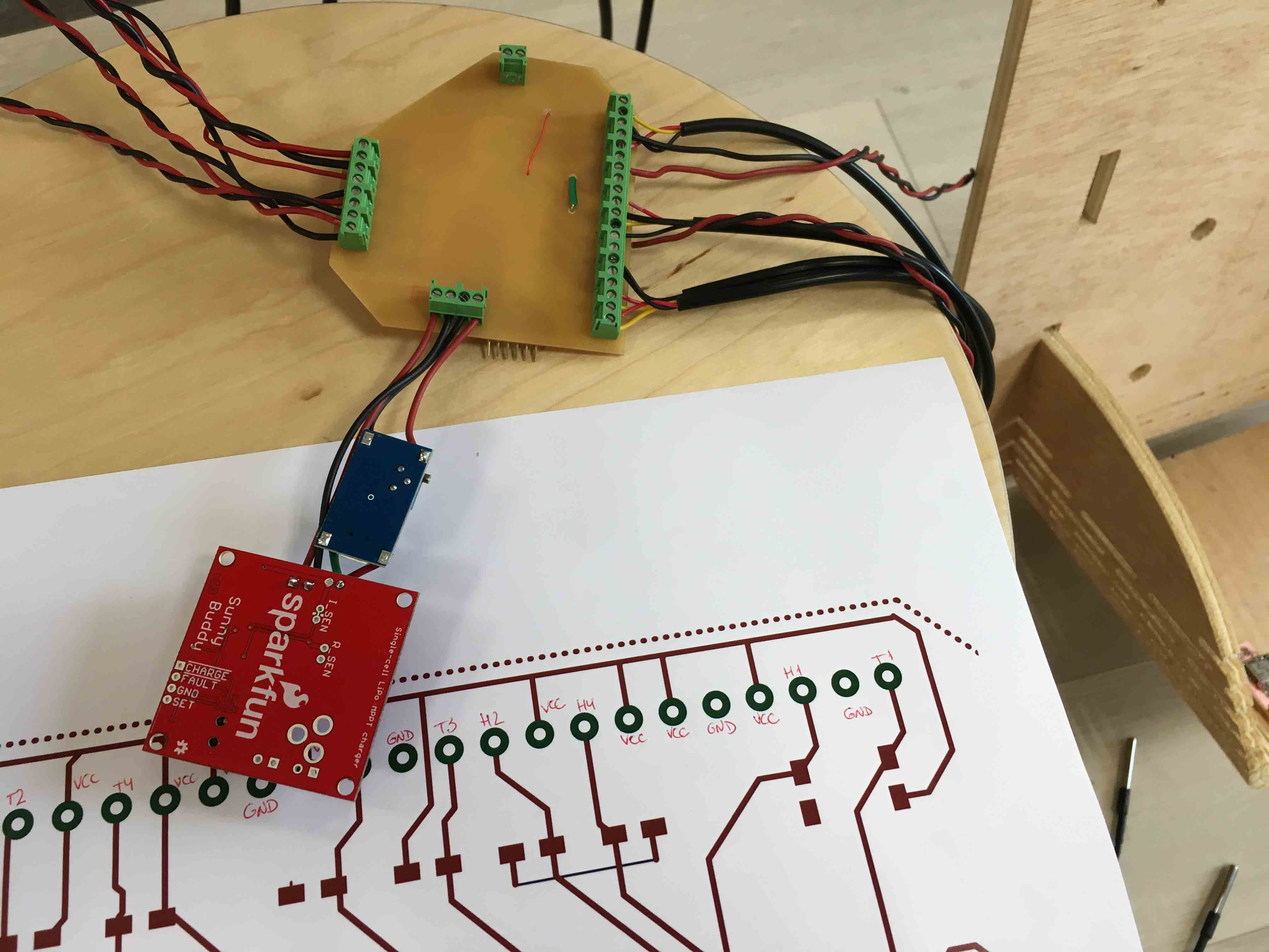
Their conexions to 3_MAIN PCB are designated as:
	_ T1, T2, T3 and T4: for temeperature sensors.
	_ H1, H2, H3 and H4: for Humidity/soil moisture sensors.
	_ E1, E2, E3 and E4: for valves.
It can be seen in Eagle BOARD design how each one is going to be connected:
I explain here below how I did Humidity/soil moisture sensors (DIY):
HUMIDITY/SOIL MOISTURE SENSORS: DIY
I saw in internet some sites how I can do a DIY Humidity/soil moisture sensors, as for example here.
It was easy, so I bought Galvanized wire and, first of all, I cut 8 equal pieces of it. I soldered red cable to 4 of them, and black cable to the other 4. For doing it more resistant, I used termoretractil cover on each soldered part.
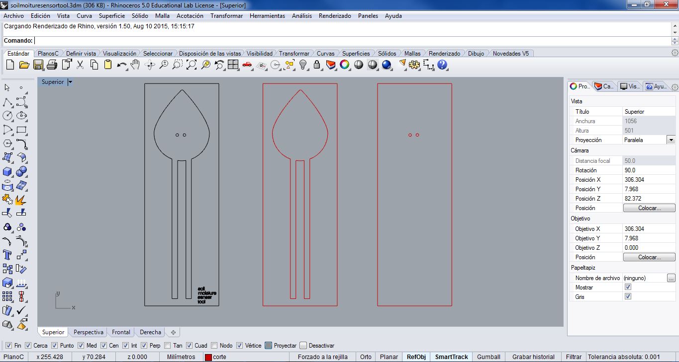
After that, I thought to make a personal design to them: I thought in a Drop-form sensor. So I did a 2D design in Rhinoceros, to cut it in PMMA in the Laser Cutter.
I cut it, and once I have prepared cables and mold, I began to prepare the material I was going to use to get toghether a red and a black cable for each sensor.
It can be made by a piece of cork, wood or foam, where they can stick the two galvanized parts. But I decided to do it with Polimaker, since I had this material in Deusto Fablab.
Polimaker is a solid polymer which it is hand-moldable with 60ºC: I took hot water, I submerged it inside, I molded it a bit with my hands, and I used the molds prepared with cables to get the shape I wanted. It get cold, more or less, in 6 minutes.
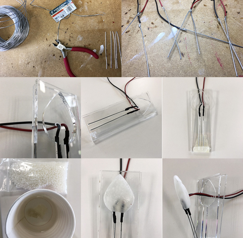
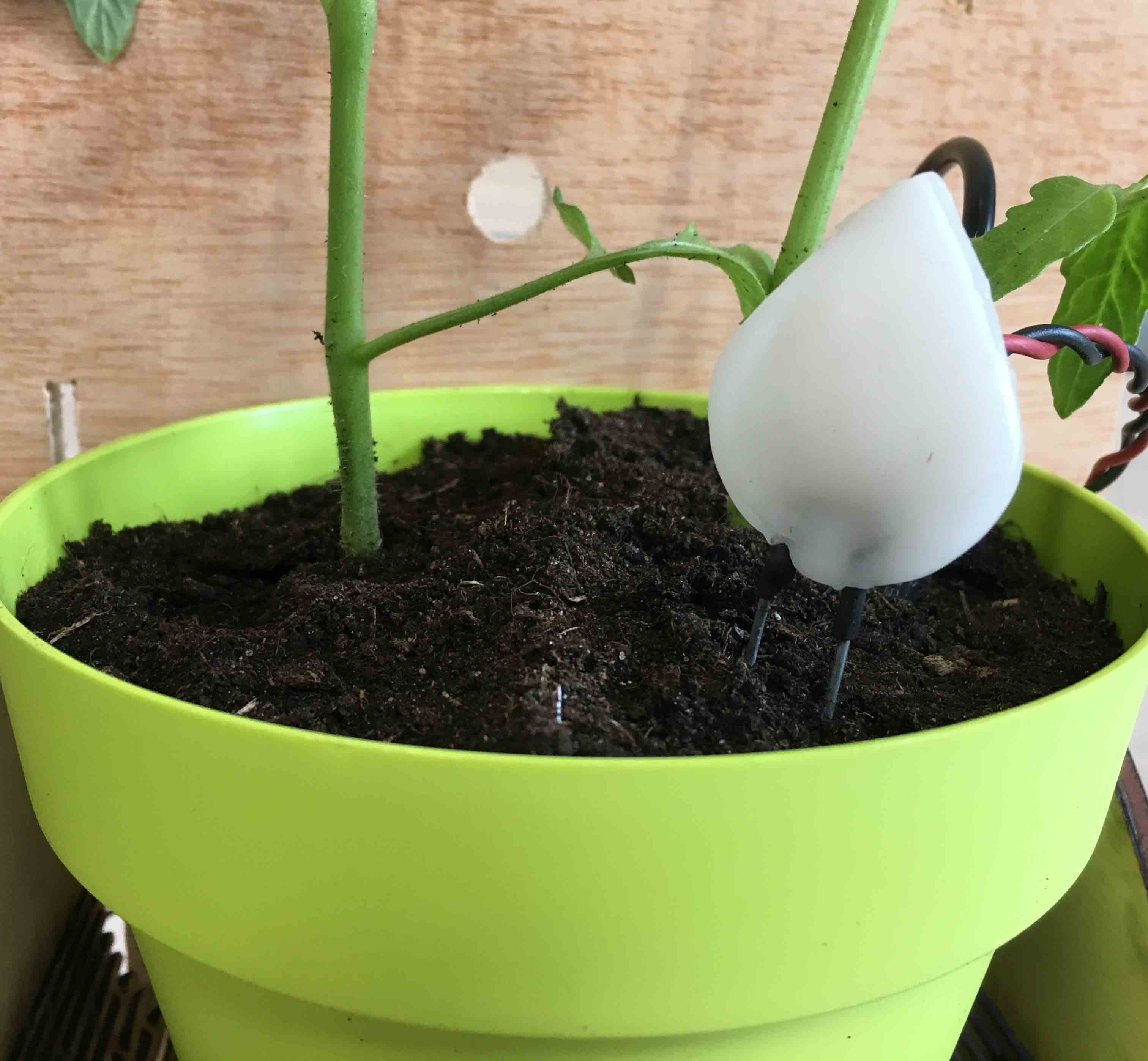
And here is result: :)
7_USER INTERFACE
During Exercise 13. Interface and applications communication; I made my first prototype, and I tested it. So in this case, I redesigned it for 4 plants, and I change some 2D plant designs and interface layout/mockup. I have been able to design, using illustrator, all .png files to show each plant humidity (3 levels), temperature and a watering button.
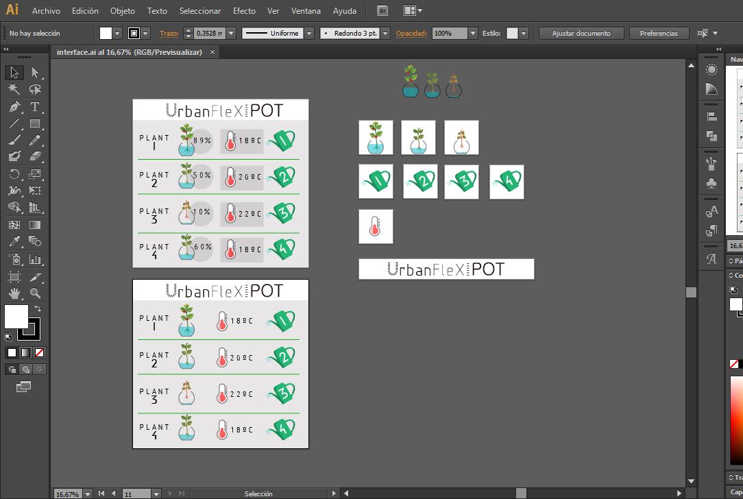
Then, I modified de html file from Exercise 13. Interface and applications communication; I added 4 DIV elements (one for each plant) and I designed their layout following my Illustrator Graphic idea.
Later, as you can see in 5_PROGRAMMING area, I linked everything with variables which made all UrbanFlexiPot work. You can find final_interface.html file into NODEJS download file, and Interface Graphics also into 2D download file, in the bottom of this site.
8_CONNECTING EVERYTHING
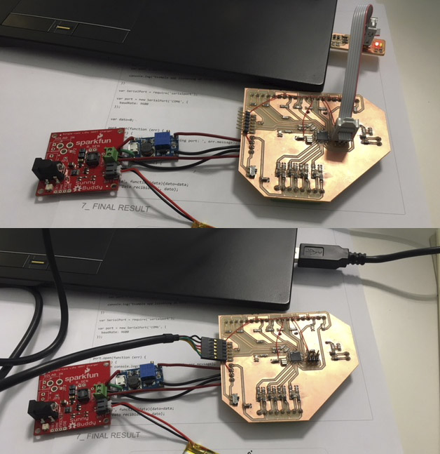
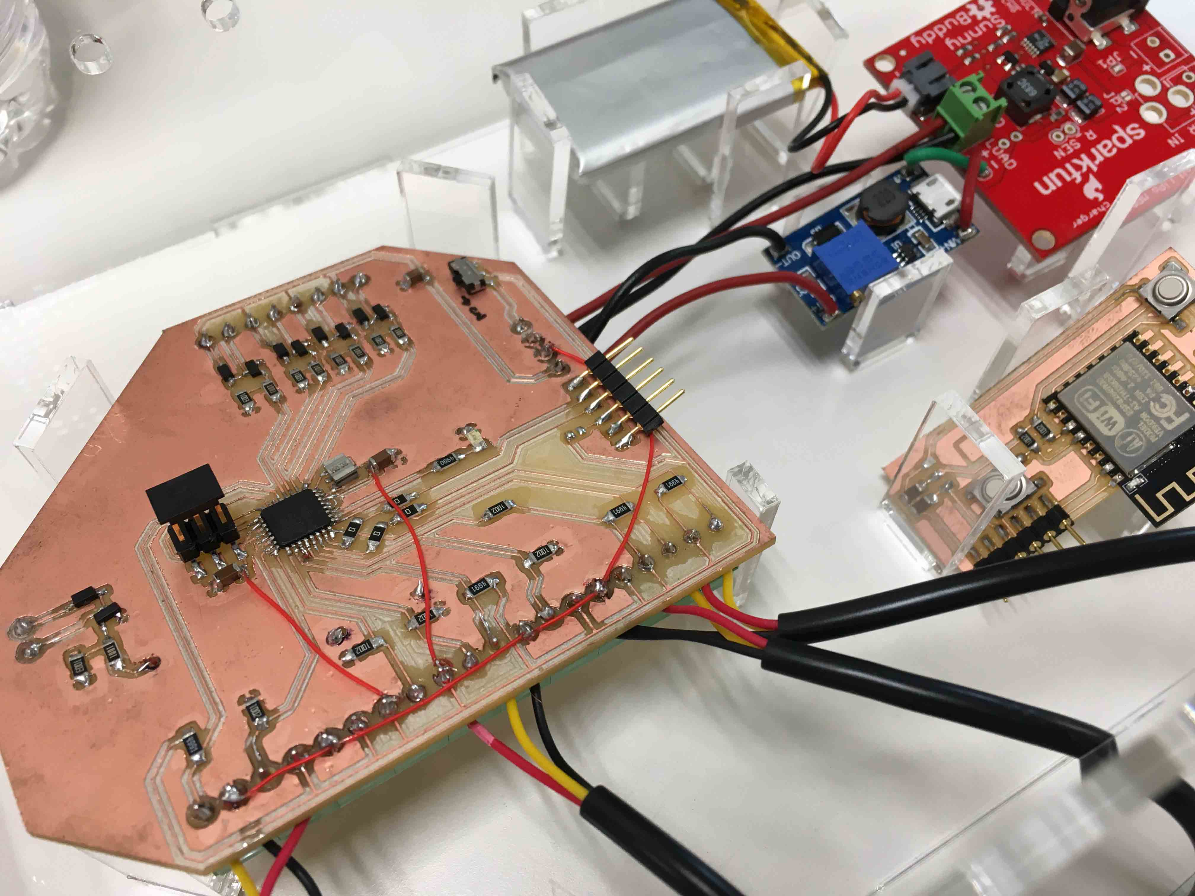
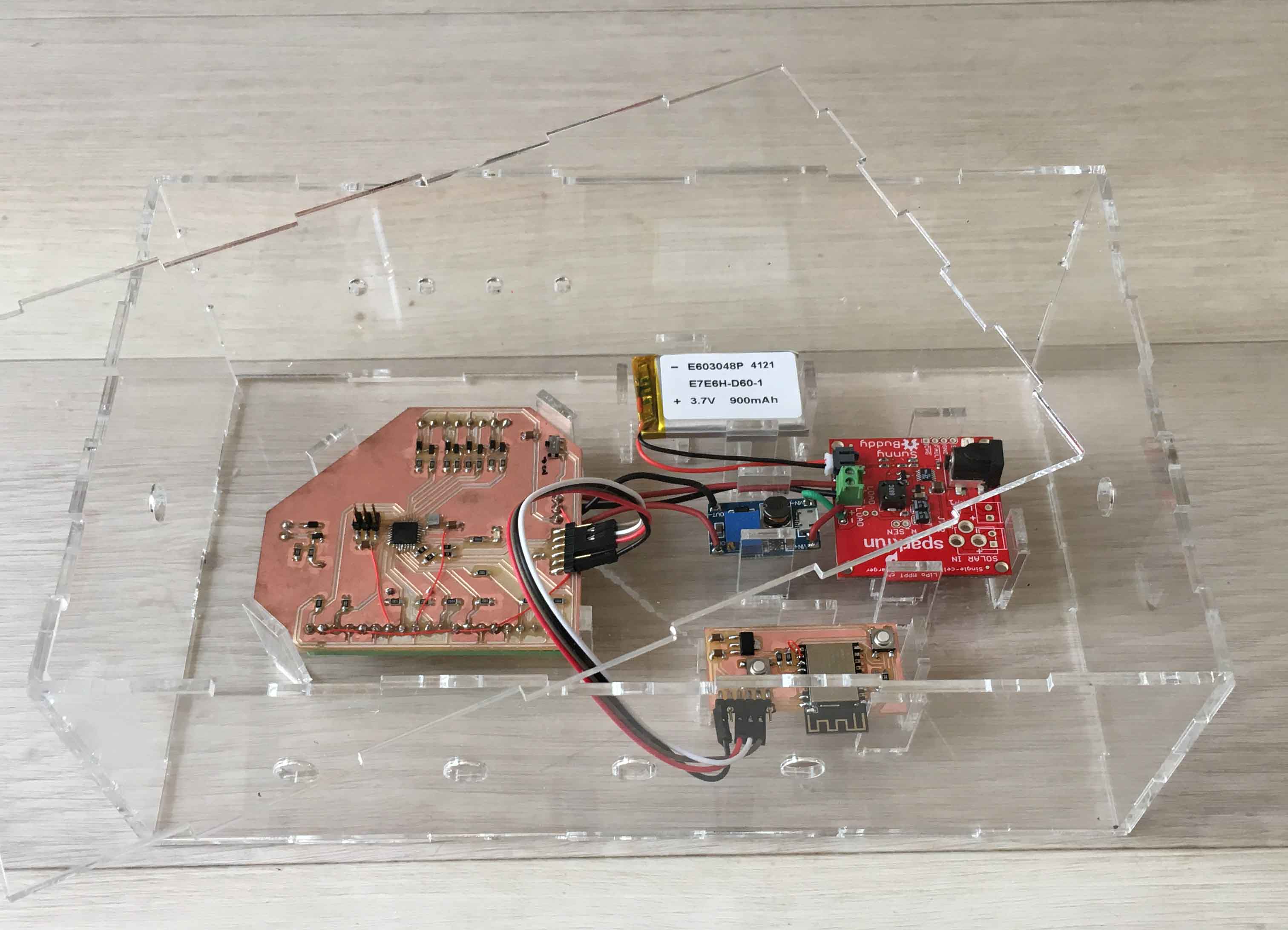
First of connecting everything for the final-final-final UrbanFleXIPot, I had to connect and test if everything was going well.
I had everything programmed, so I connect all wired connections for solar power-supply, 12V regulator, WIFI_BOARD, and some sensors, and I connected my movil phone to the server Interface.
*I soldered MAIN-PCB's J1 jumper to make WIFI_PCB work (in the first attempt I forgot it :S)
*There is no valve connected on this video, but the signal to know if valve-opned action arrives to MAIN-PCB is the red led which switches ON in these cases.
It worked! :D
9_SYSTEM PACKAGING
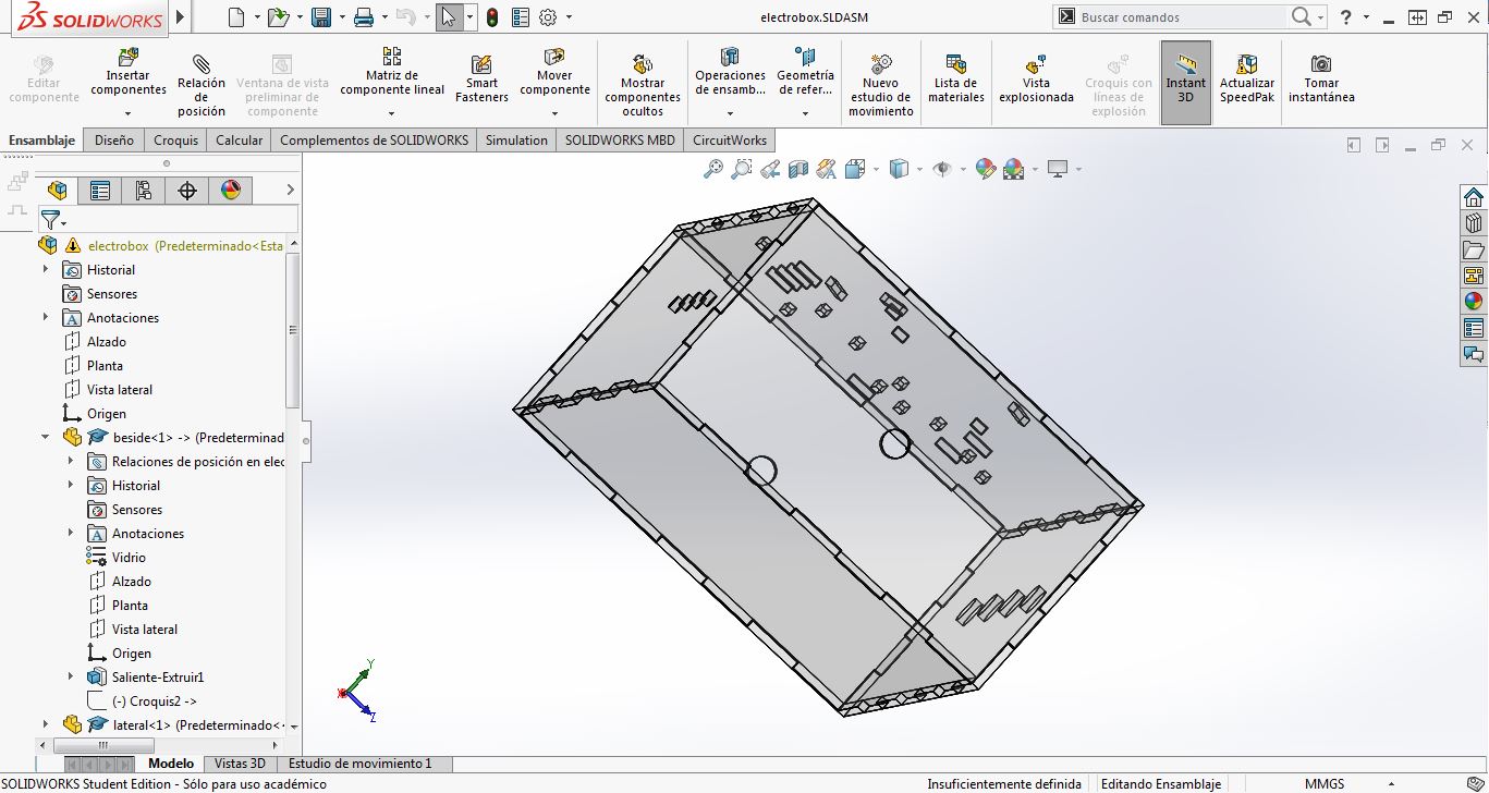
For packing all electronics component, as I projected in MODULE 3D assembly, I made a PMMA box, in the Laser Cutter.
I designed it first in Solidworks:
Then, I export 2D designs to Rhinoceros, and I modify Press-fits to fix them well.
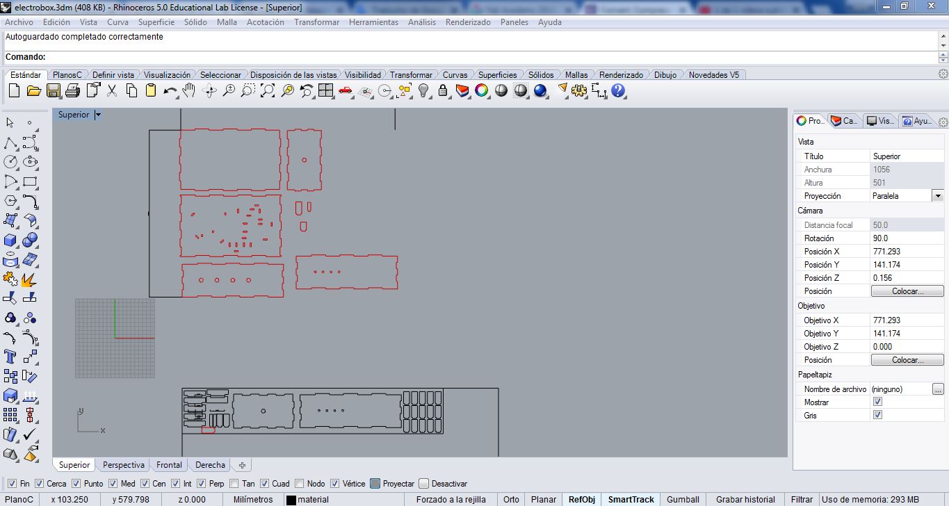
I cut all box parts, and I assembled everyone in its position:
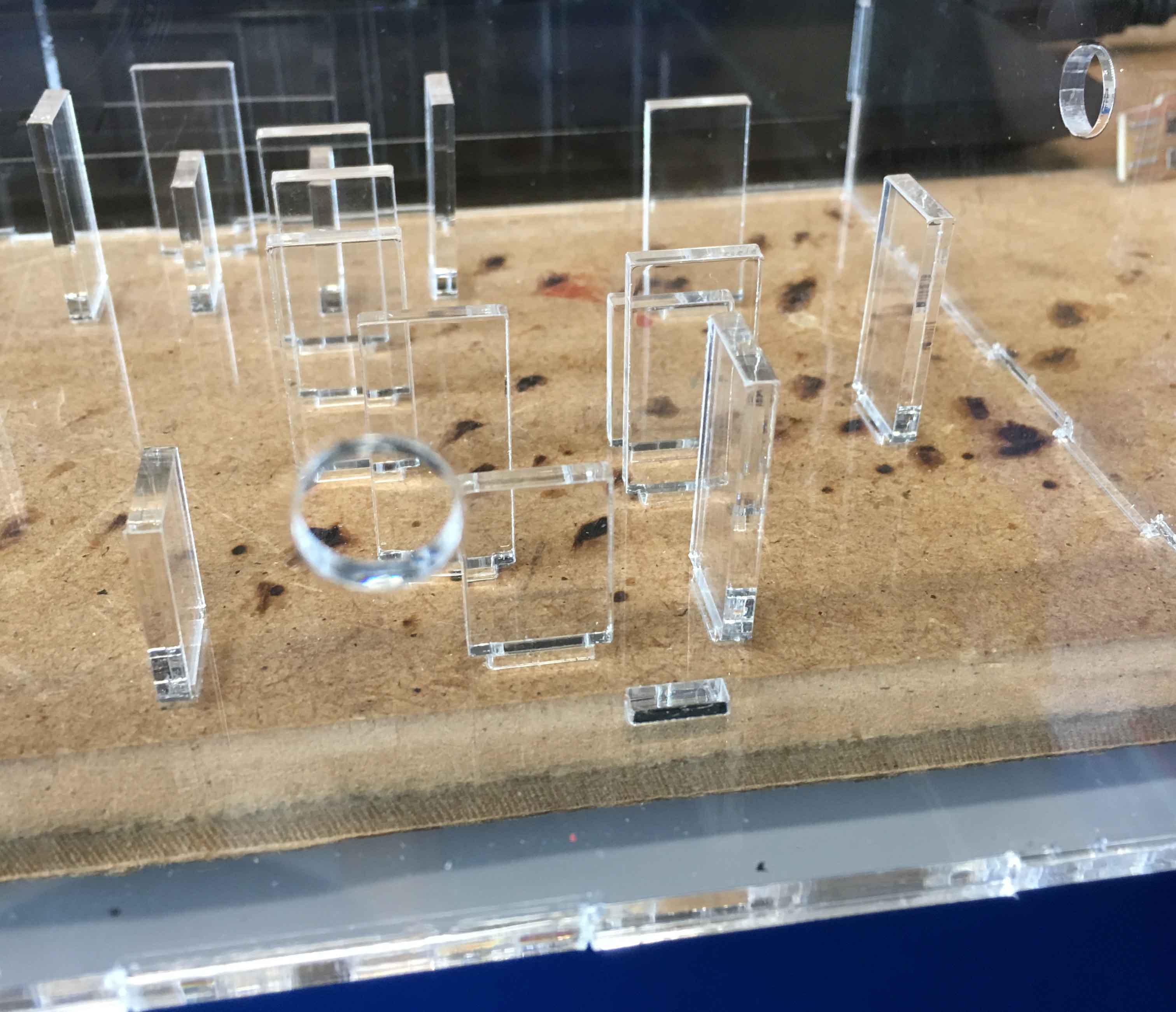
As I respected the exact measurements of each electronic component that should fit, when checking it, everything was perfect:
:)
10_ASSEMBLY OF EVERYTHING
AND IT IS TIME TO ASSEMBLE EVERYTHING!
Connect all sensors and valves to 3_MAIN PCB, but using 9_SYSTEM PACKAGING BOX.
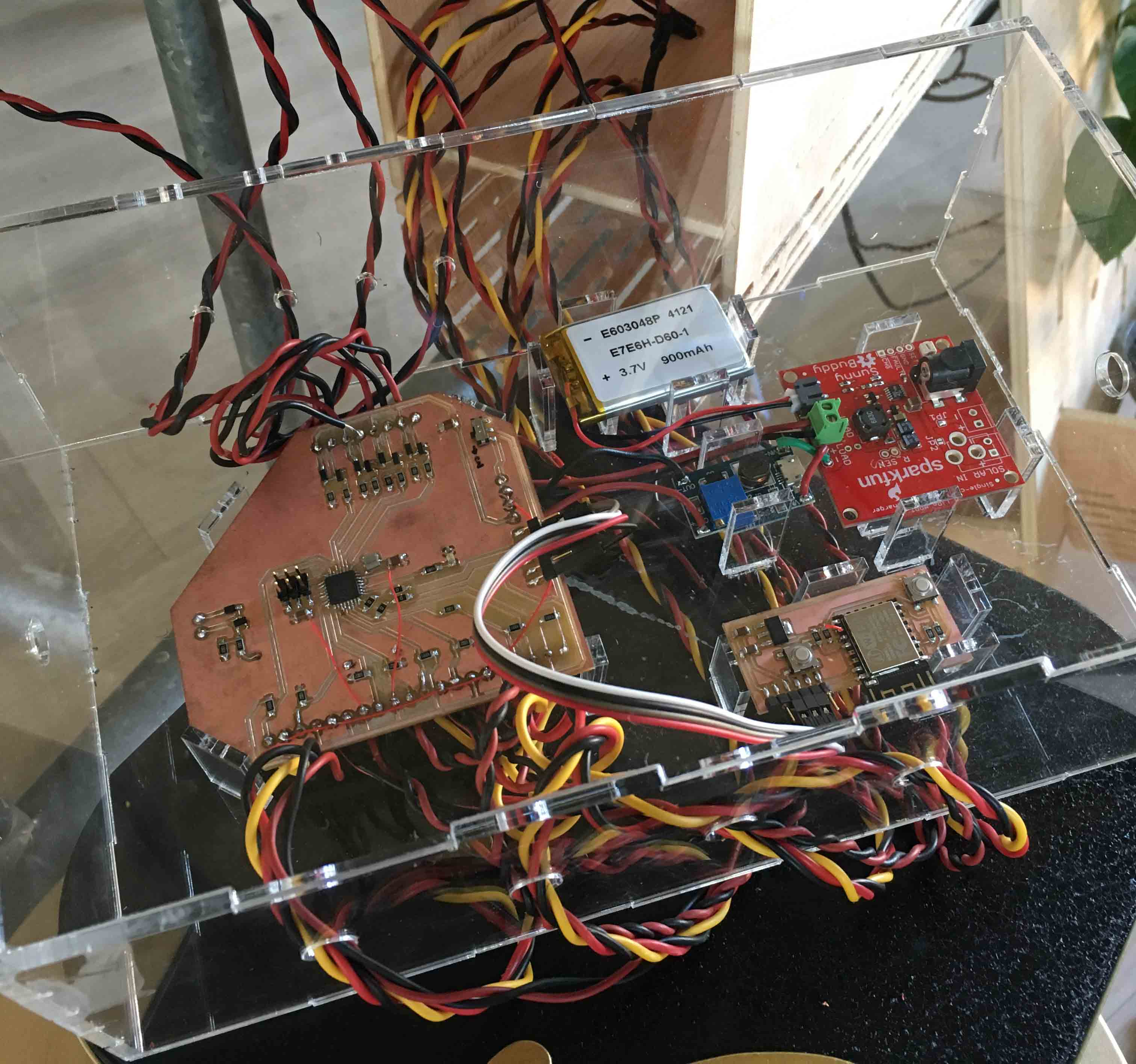
I realized that it has been a little bit difficult due to cable-holes proximity and dimmensions, for a future version I am going to improve this BOX design.
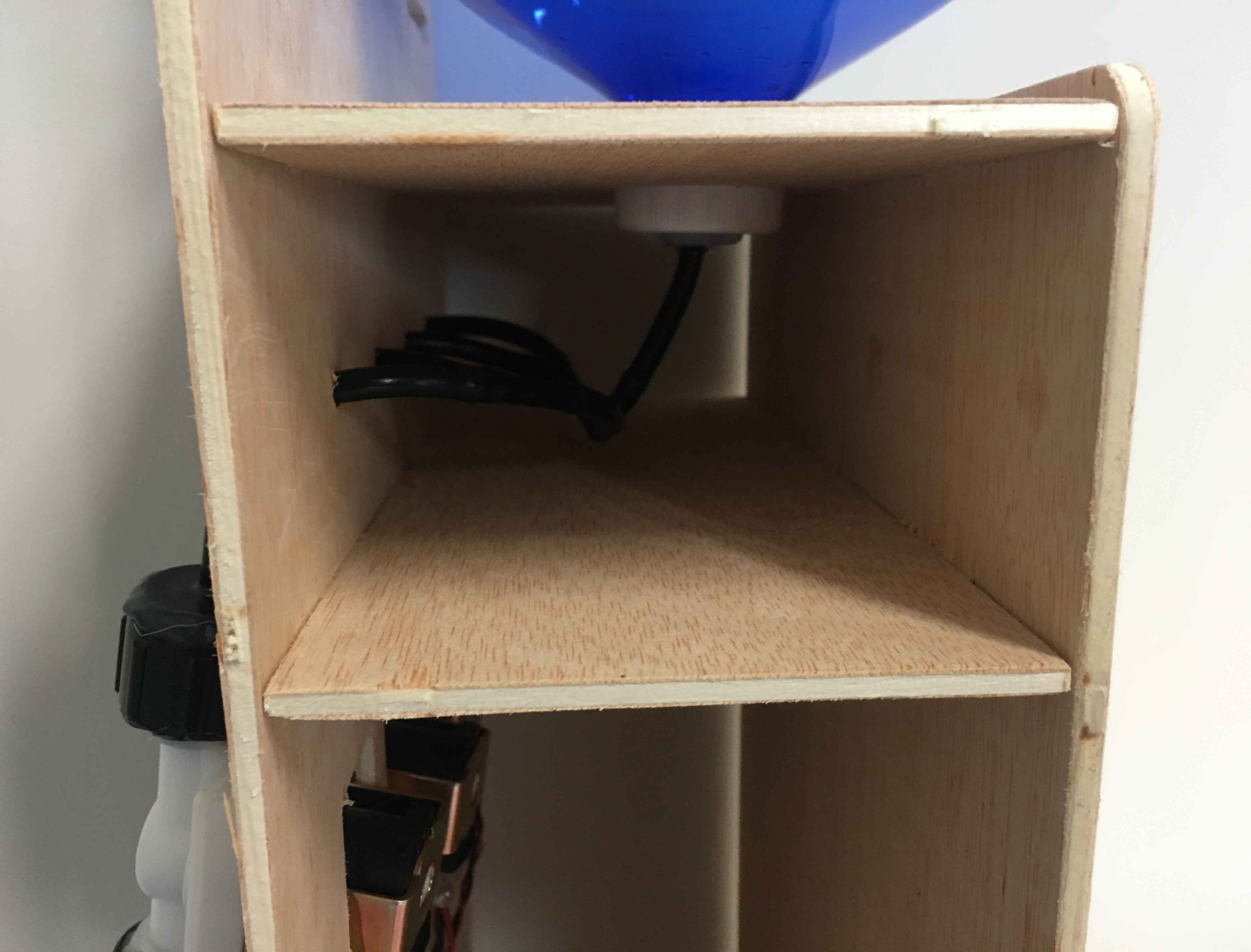
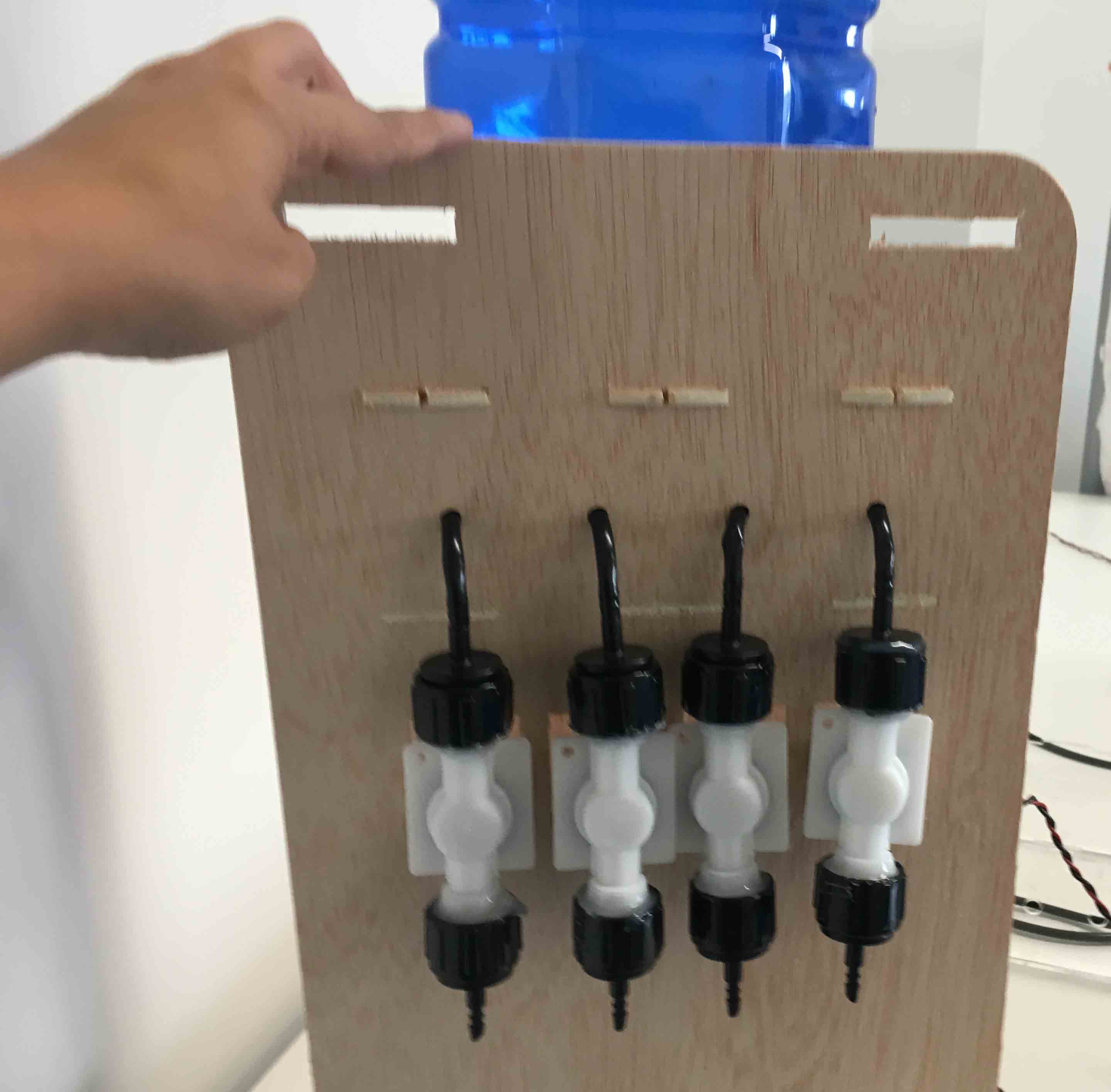
On the other hand, assemble MODULE with valves, water tank and its water-tubes:
Assemble everything, one thing next to the other:
And TANTANTXAAAAN! :) :)
11_TESTING
I have been testin 1_MAIN STRUCTURE and POT HOLDERS since I did them on April 2018: They are very resistant!
And here, in this video below, you can see how all toghether is working RIGHT! It waters each plant I need!
FUTURE PLANS
UrbanFleXIPot is working, but It has, in my opinion, things to improve and develop yet:
		CONSTRUCTION details:
		_ Make sensor cables longer, I had some problems with it.
		_ Readjust Packaging BOX to make easier cables-MAINPCB connections.
		_ Make an APP (with APP inventor, for example) with  similar interface,
		but with user accounts. (at this moment, everyone has access to my interface page can water my plants!!)

		FUNCTIONAL details:
		_ Make a tank of water adjusted to the design, and that has an easy collection of rainwater.
		Respecting the fall of water by gravity.
		_ For those users in which balcony is difficult to have a gravity-tank: design a water-tank to
		adjust it in the back-folder of the MAIN-STRUCTURE.
			>> In this case: Add a water pump and reprogram the system.
		_ Evaluate to add some other systems, for example:
			>> A programmable awning for sunny days, also controllable from the interface.
			>> Dishes of self-rotating pots.
DOWNLOADS
_ 3D files: SolidWorks files, .STL and .EASM
_ 3D PRINTING files: .STL, .GCODE and .3MF
_ 2D CUTTING and MILLING files: .DXF and .3DM
_ EAGLE PCB designs: .SCH, .BRD, .BMP
_ NODEJS files, for SERVER and INTERFACE
_ ESP WIFI board FIRMWARE files