Exercise 14. networking and communications
After the lesson about networking and communications, on Wednesday 25th April, the assignment for this week was to:
		INDIVIDUAL ASSIGNMENT:
			_ design and build a wired &/or wireless network connecting at least two processors.


		GROUP ASSIGNMENT:
			_ send a message between two projects.
Learning Outcomes:
		_ Demonstrate workflows used in network design and construction.
		_ Implement and interpret networking protocols.
PREVIOUS CONSIDERATIONS
INDIVIDUAL ASSIGNMENT
I would like to comment, first of all, that I had have a lot of problems with this exercise: forgotten elements in PCB design and short circuits. So, after all, I was able to do the exercise, but not as I would have liked.
First of all I have planned my activity: I would like to make a new PCB which will communicate PCB made in exercise 13, and receive sensors data to send by WIFI signal to Node.js site created in this precedent exercise.
1_ Design, make and solder PCB
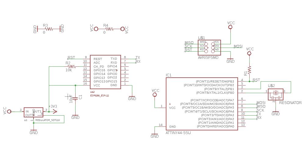
For doing it I have opened Eagle, and with the same procedure as in exercise 7, electronics design, I have added all the components I thought I needed and I connected them, positioning them later in Eagle’s board view generating routes.
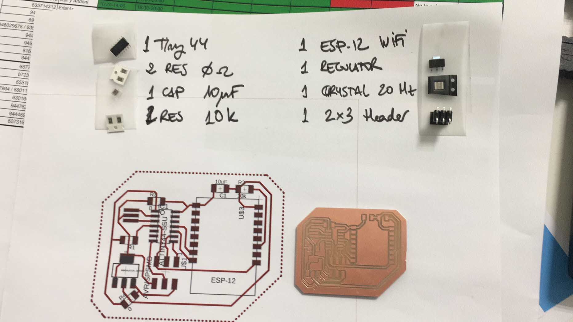
Components I have used are:
		_ ATTiny44-SSU, micro-controller
		_ ESP8266_ESP12, WIFI module
		_ CAP UNPOLARIZEDFAB, 1uf capacitor
		_ AVRISPSMD, 2x3 header
		_ RESONATOR, 20MHz crystal
		_ RES-US1206FAB, resistors:(2) 10k ohm
		_ REGULATOR SOT223
I have used also two 0 ohms resistances to make bridges, and everything seemed to be ok.
A regulator is needed due to its operation voltage between 3V and 3,6V.
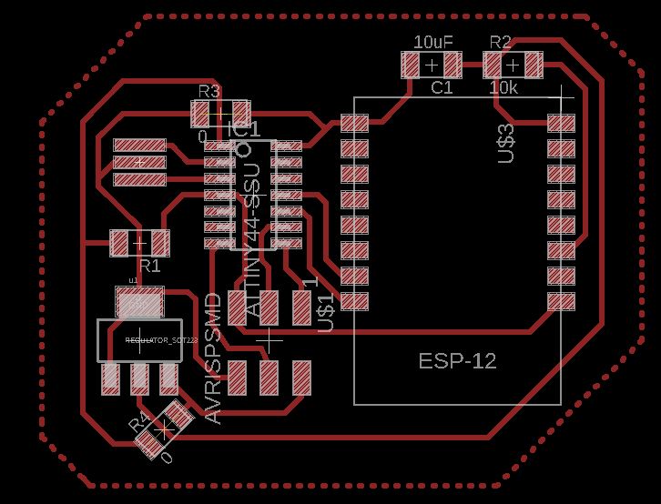
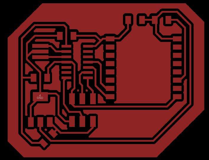
I made the perimeter polygon, and in this mode I created the image needed to export to our Rolang Milling Machine:
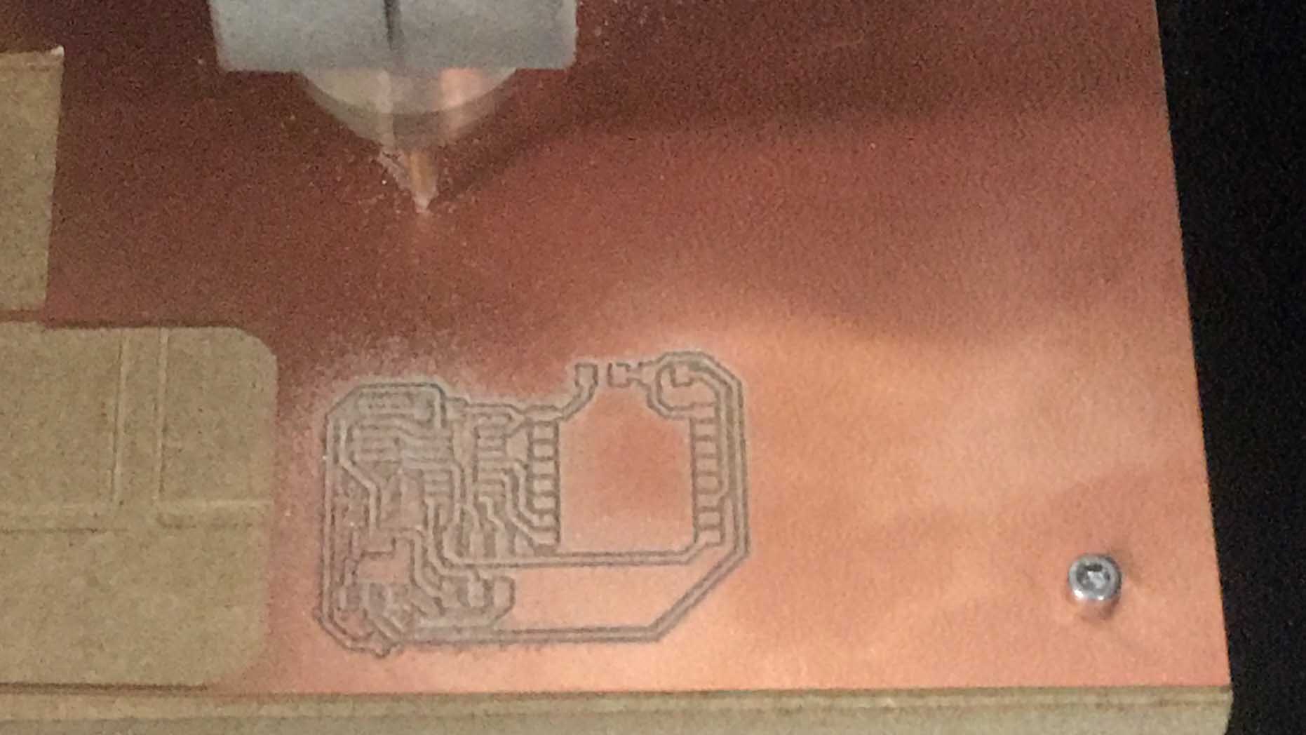
I milled it:
And I took all components needed, I prepared them to solder:
Finally, I soldered them:
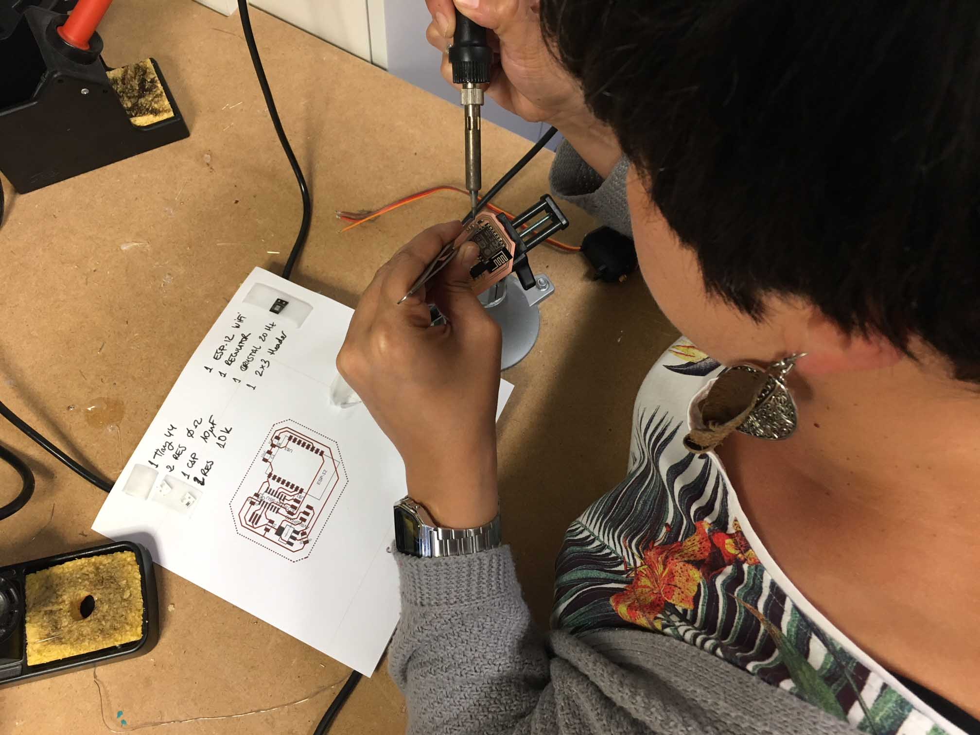
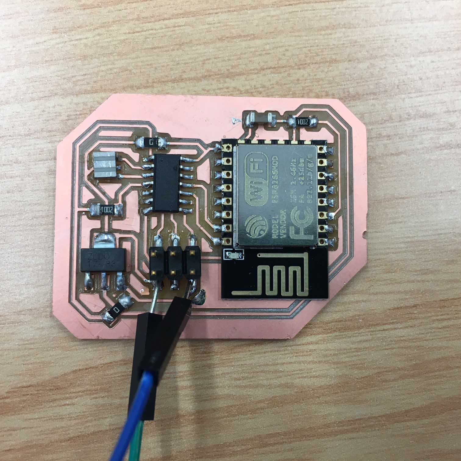
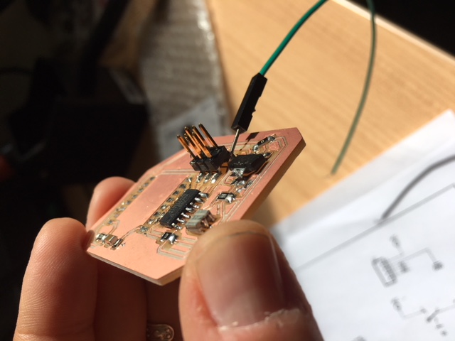
And this was the result (without these two other cables :S I have not a photo before beginning to have problems):
2_ ESP Firmware config
FIRST PROBLEM: I have not add any FTDI. So, to see if it has installed its firmware, I had to connect FTDI wires to Ribbon connector.
For doing it I soldered a wire to GND and another one to VCC, as you can see in the previus picture. In this way we feed the PCB to be able to program it.
Using Arduino, I would like to program code to connect PC to Tiny, Tiny to ESP12, and ESP12 answers to PC via Tiny.
But first of all I needed to verify if ESP12 could work. Using Arduino library I opened the communication example for SerialPassthrough (sketch).This sketch allows you to emulate the serial passthrough behaviour. Any text you type in the IDE Serial monitor will be written out to the serial port on Digital pins 0 and 1, and vice-versa.
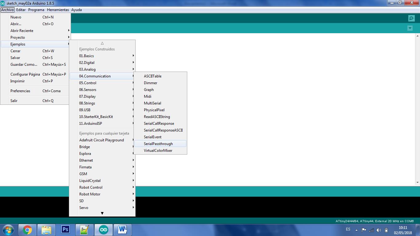
This is the SerialPassthrough sketch code:
#include//include library which implements software serial port, for comunication const byte rxpin = 6; //not variable, reception on pin MOSI from the other (sensor)PCB const byte txpin = 5; //not variable, transmision on pin MISO. Sends message to the other (sensor)PCB, communication of micro-controller with the other (sensor)PCB. const byte rxpin2 = 0; //not variable, reception on pin 0 from PC const byte txpin2 = 1; //not variable, transmision on pin 1. Sends message to PC, communication of micro-controller with PC. SoftwareSerial mySerial (rxpin, txpin); //set up a new serial object, and say which pin is for reception and which for trasmision SoftwareSerial mySerial2 (rxpin2, txpin2); //set up a new serial object, and say which pin is for reception and which for trasmision void setup() { mySerial.begin(9600); mySerial2.begin(9600); } void loop() { if (mySerial.available()) { // If anything comes in Serial (USB), mySerial2.write(mySerial.read()); // read it and send it out Serial2 (pins 0 & 1) } if (mySerial2.available()) { // If anything comes in Serial2 (pins 0 & 1) mySerial.write(mySerial2.read()); // read it and send it out Serial (USB) } }
For programing it I decided to connect it to a power supply: In my opinion ESP12 was going to need more energy than a FTDI-USB connection cable.
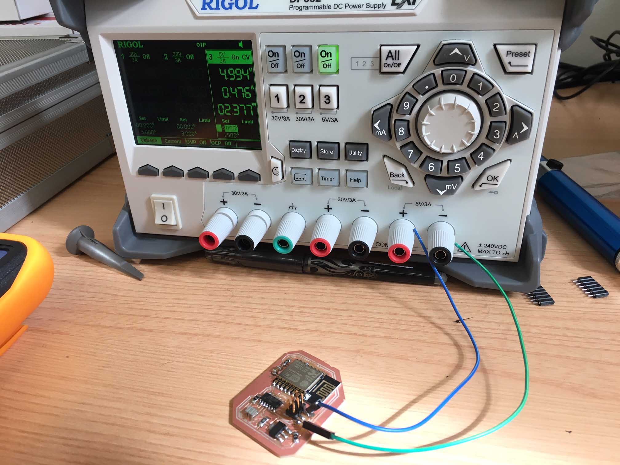
SECOND PROBLEM:There is a short circuit and I needed to find it.
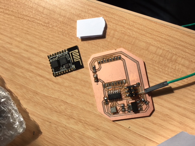
As ESP12 wifi module has been difficult to solder, and its soldering pins are touching its base, I thought it could be the main problem.
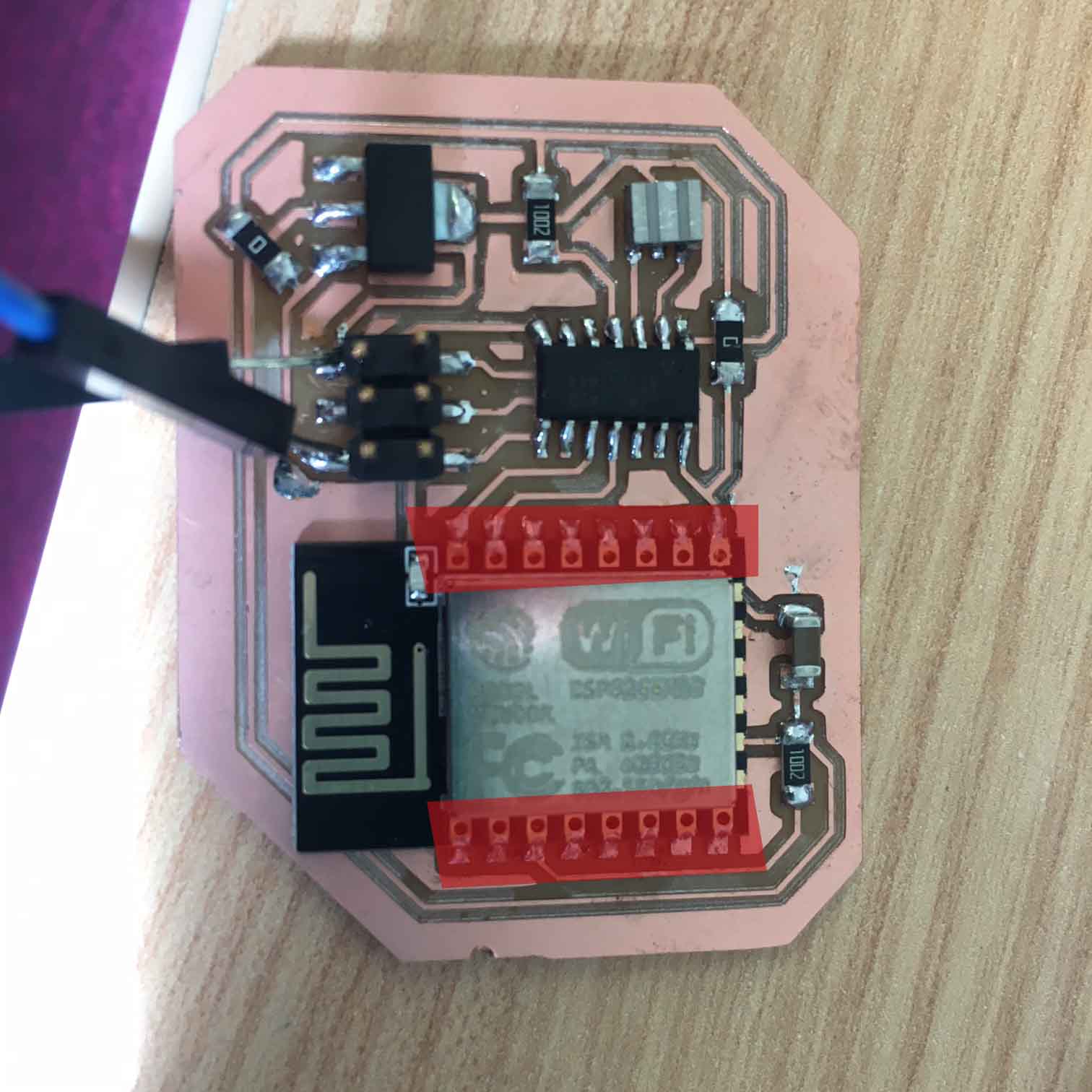
So I desoldered ESP12 from my PCB, and I realized it was not the short circuit reason.
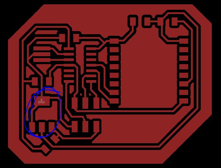
The other component which was new for me was the REGULATOR_SOT223, and I decided to review its connections.
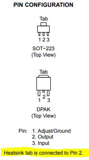
I have made a mistake! The tab should be connected to Output pin, and I have connected it to GND.
I tested to program it again in this new conditions:
AND IT DOES NOT WORK! :(
So, I discarded it, I had no time to this week to do another new PCB, and I tested communications connecting two of PCB made in week 7 and week 13.
3_ Program and conect, for communication.
Communication between w7-PCB and w13-PCB would be, simulating a real plant humidity state and user's watering action, next one:
		1. w13-PCB takes from Soil-moisture sensor humidity data.
		2. w13-PCB sends this information to w7-PCB by serial-port: "0" if it is good (H>70%),
		"1" if it is regular (70%>H>40%), "2" if it is bad (H<40%)
		3. If w7-PCB reads "2", its led switches ON to notify the user that the plant is dry.
		4. If the user decides to water the plant, press the button on w7-PCB.
		5. Button on w7-PCB sends a signal, a "1", to w13-PCB.
		6. If w13-PCB receives a "1" by serial-port, it switches ON its Led.
W13-PCB was programmed since exercise 13, so I took w7-PCB and I wrote a simple program, using Arduino, to make the communication I wanted:
#includeint pinButton = 2; int pinLed = 3; int previusState = 0; int actualState; const byte rxpin = 0; const byte txpin = 1; //set up a new serial object SoftwareSerial mySerial (rxpin, txpin); void setup() { // put your setup code here, to run once: pinMode(pinButton, INPUT); pinMode(pinLed, OUTPUT); mySerial.begin(9600); } void loop() { // put your main code here, to run repeatedly: int dato=mySerial.read(); //It is reading everytime if w13-PCB sends a signal if (dato==50){ //if it is a signal "2" digitalWrite(pinLed, HIGH); //Switch on Led for 5 seconds, then Switch off it. delay(5000); digitalWrite(pinLed, LOW); } actualState = digitalRead(pinButton); //if user switches on button if ((actualState == HIGH) && (previusState == LOW)) //and it was switched OFF before { mySerial.write("1"); //it sends a "1" signal to w13-PCB by serial port } previusState = actualState; delay(20); }
And I have programmed it without problems.
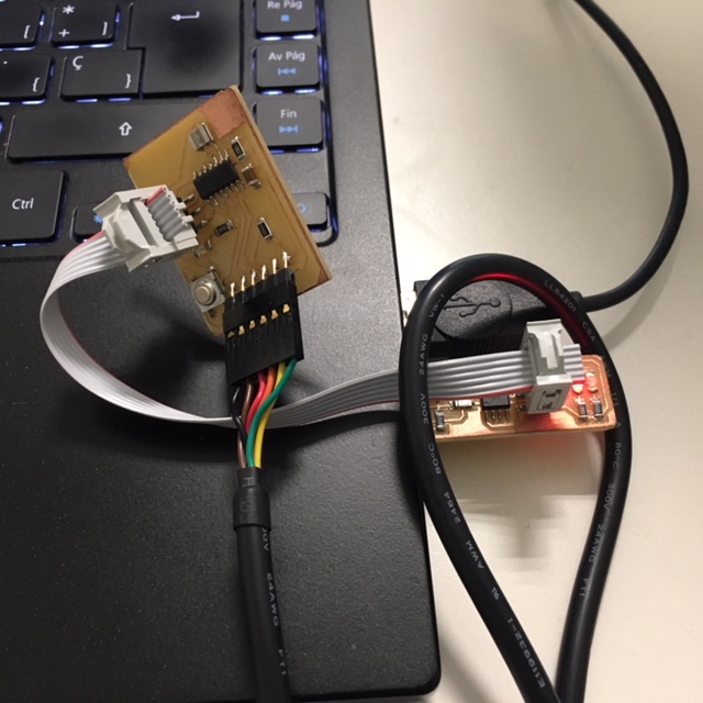
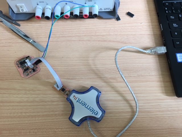
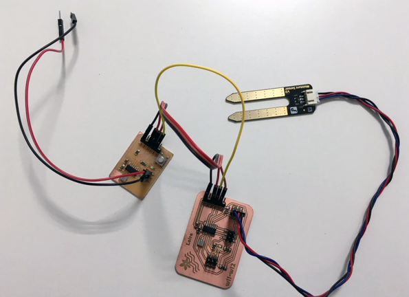
As I have used FTDI connection between them, I had to use AVRISPSMD, 2x3 header, VCC and GND connections to connect them to a power suply, and...IT IS WORKING!!!
You can see a connection photo and a video below (I gave humidity with a wet paper):
GROUP ASSIGNMENT
For the group assignment we decided to connect my w13-PCB to Javi's w14 PCB system.
Communication between Javi-PCB system and w13-PCB would be, simulating a real plant humidity state and user's watering action, next one:
		1. w13-PCB takes from Soil-moisture sensor humidity data.
		2. w13-PCB sends this information to Javi-PCB system by serial-port: "0" if it is good (H>70%),
		"1" if it is regular (70%>H>40%), "2" if it is bad (H<40%)
		3. If Javi-PCB system reads "2", its BUZZER switches ON to notify the user that the plant is dry.
		4. If the user decides to water the plant, press the SWITCH button ON in Javi-PCB system.
		5. Button on Javi-PCB system sends a signal, a "1", to w13-PCB.
		6. If w13-PCB receives a "1" by serial-port, it switches ON its Led.
W13-PCB was programmed since exercise 13, so we took Javi-PCB system and we wrote a simple program, using Arduino, to make the communication we wanted:
In this programming action we had A PROBLEM WITH TINY44 CAPACITY, I did not have space for the program, so:
		1_ We changed myserial.print for myserial.write:
		"print" manages string data and we were sending only a carachter ("1"),
		"write" sends only a byte, so it is lighter and enough for it.
		2_ We change "delay" of the "loop":
		we were testing different actions to reduce memory,
		and it seemed to be a right option.
With this code it was to 94% of capacity:
const byte rxpin = 0; //not variable, reception on pin 0 const byte txpin = 1; //not variable, transmision on pin 1. Sends message. #include//include library which implements software serial port, for comunication SoftwareSerial mySerial (rxpin, txpin); //set up a new serial object, and say which pin is for reception and which for trasmision #include char c=0; char ca=0; int dato; void setup() { Wire.begin(); // join i2c bus (address optional for master) mySerial.begin(9600); //bits per second, 9600 is standard speed } void loop() { dato=mySerial.read(); //It is reading everytime if (dato==50){ //49=Character "1" in Dec, if user send signal, it will be 1, if not 0. Wire.beginTransmission(9); // transmit to device #9 Wire.write(1); // sends one byte Wire.endTransmission(); // stop transmitting } if (dato==49){ //49=Character "1" in Dec, if user send signal, it will be 1, if not 0. Wire.beginTransmission(9); // transmit to device #9 Wire.write(0); // sends one byte Wire.endTransmission(); // stop transmitting } if (dato==48){ //49=Character "1" in Dec, if user send signal, it will be 1, if not 0. Wire.beginTransmission(9); // transmit to device #9 Wire.write(0); // sends one byte Wire.endTransmission(); // stop transmitting } Wire.requestFrom(8, 1); // request 6 bytes from slave device #8 if (Wire.available()) { // slave may send less than requested c = Wire.read(); // receive a byte as character if((c==1)&&(ca==0)){ mySerial.write (49); //Sends a "1" signal to NODE.JS program } ca=c; } delayMicroseconds(10000); }
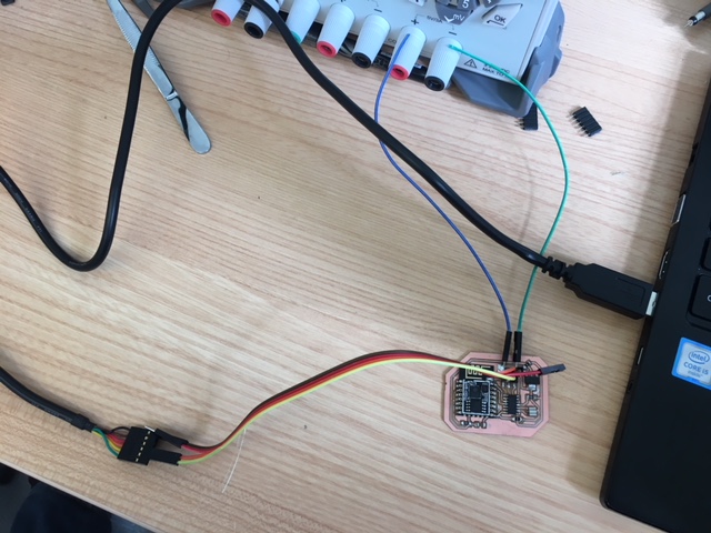
Javi has two jumpers which has to be desoldered to program PCB and when it is programmed to be soldered again:
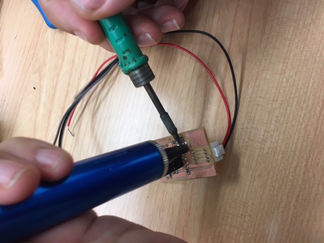
And we programmed it:
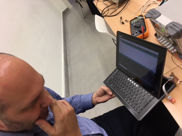
YEAH!It worked! See video linked below:
DOWNLOADS
_ 1st ESP-PCB wrong board files: Eagle, BMP and Arduino