Exercise 08. Computer-Controlled Machining
SITUATION
After the lesson about Electronics Design, on Wednesday 7 March, the assignment for this week was to:
Make Something BIG
PREVIOUS CONSIDERATIONS
DEUSTO FABLAB MILLING MACHINE
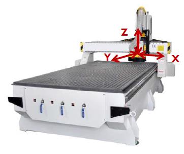
The milling machine we have is CNC TEC-CAM 1103 S-6.0, view image below:
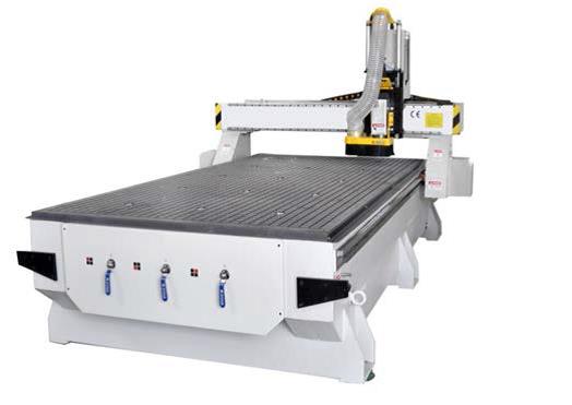
It is a subtractive process machine, process called too machining or metal removal. It consists of cutting the material with a rotary tool (milling cutter) of one or more lips. This cut is made by combining the rotation of the tool with displacement (of the tool, of the table or combined).
Different materials can be machined, cut both as milling or engraving of: methacrylate, PVC, DM, solid wood, brass, porexpan, foam and more.
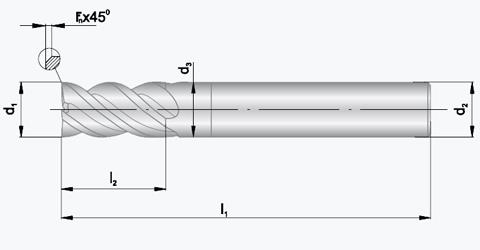
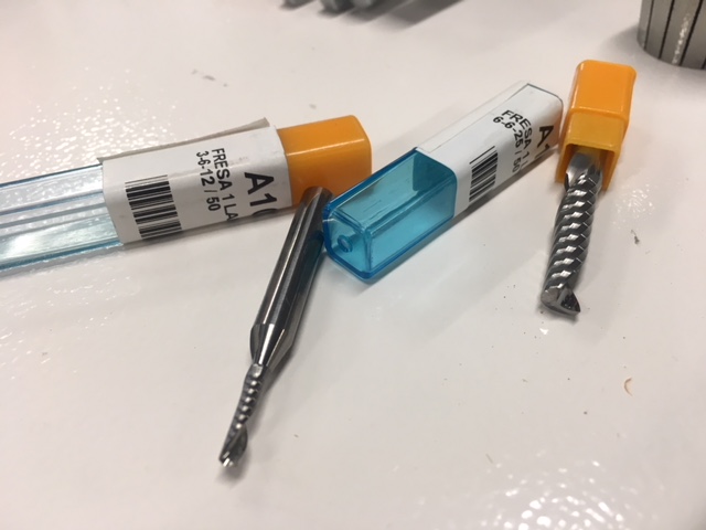
Important concepts to take in account for selection of end mills:
		•	Cut diameter d1
		•	Shank Diameter d3
		•	Cutting Depth l2
		•	Total Length l1
		•	Tool type
		•	Number of lips
		•	Type of material
		•	Material width
		•	Displacement speed
		•	Turning speed
DESIGN CONSIDERATIONS
Important concepts to take in account in the Design Process:
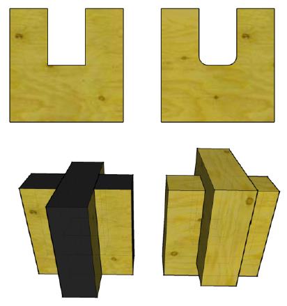
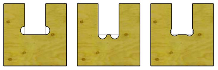
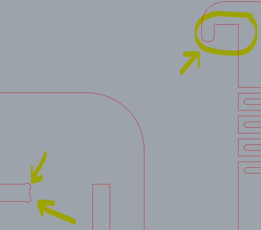
_ This process is not capable of making 90º internal pointed corners, due to the tool used. We have to prepare this corners first of machining if we want to assemble them with other parts. See examples below:
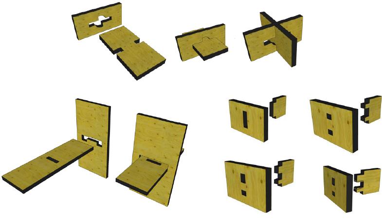
_ There are a lot of ways to assemble using digital Joints between flat parts:
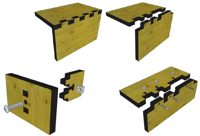
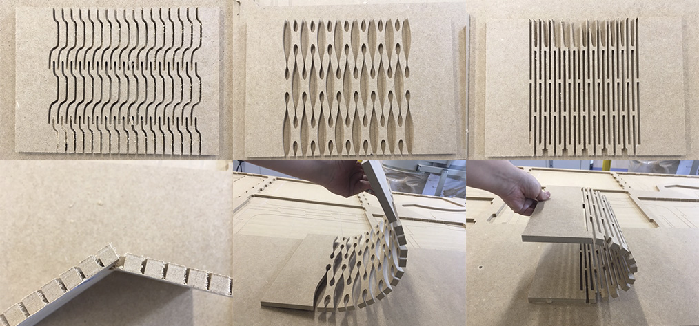
_ There are different assembly and structural types in which we can work:
		•	CNC joinery
		•	Digital joints
		•	Living hinges
		•	Flextures
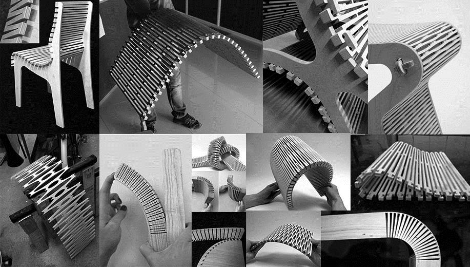
Watching what exists:
ASSIGNMENT
MACHINING STEP BY STEP
1_DIGITAL PROCESS
*We did this first part in group, with explanations from our instructor Szilard Kados.
		1.	Do design by 2D/3D software
		2.	Export it in DXF format
		3.	Open VCarve software.
VCarve provide a powerful but intuitive software solution for cutting parts on a CNC Router, and we have it in Deusto FabLab.
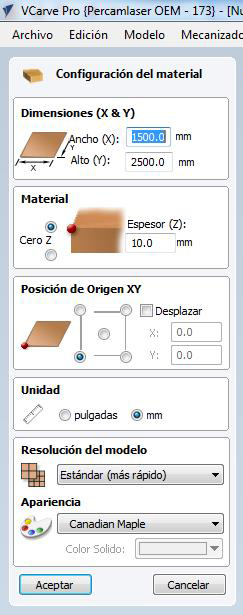
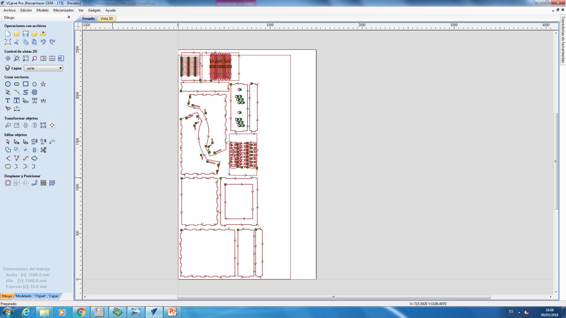
4. Enter material dimensions and select working origin-point situation.
(in this case 10 mm DM sheet, and 1500x2500 mm workspace, origin down-left point)
5. Import DXF file.
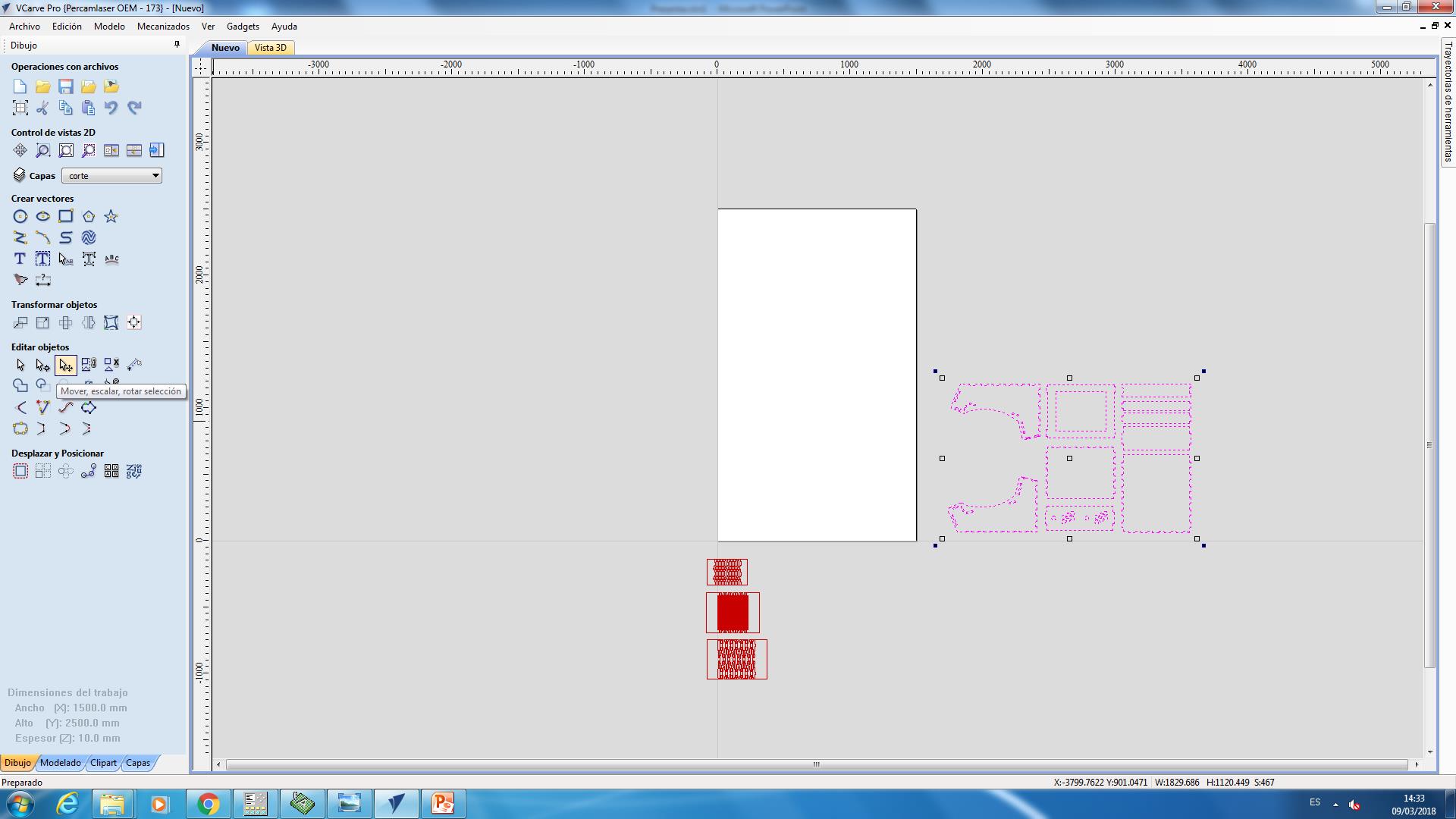
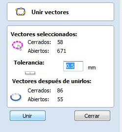
6. Unify all design lines/objects.
When we import DXF to VCarve, it separates all segments.
7. Move/rotate/”tetrix” it to select best material optimization.
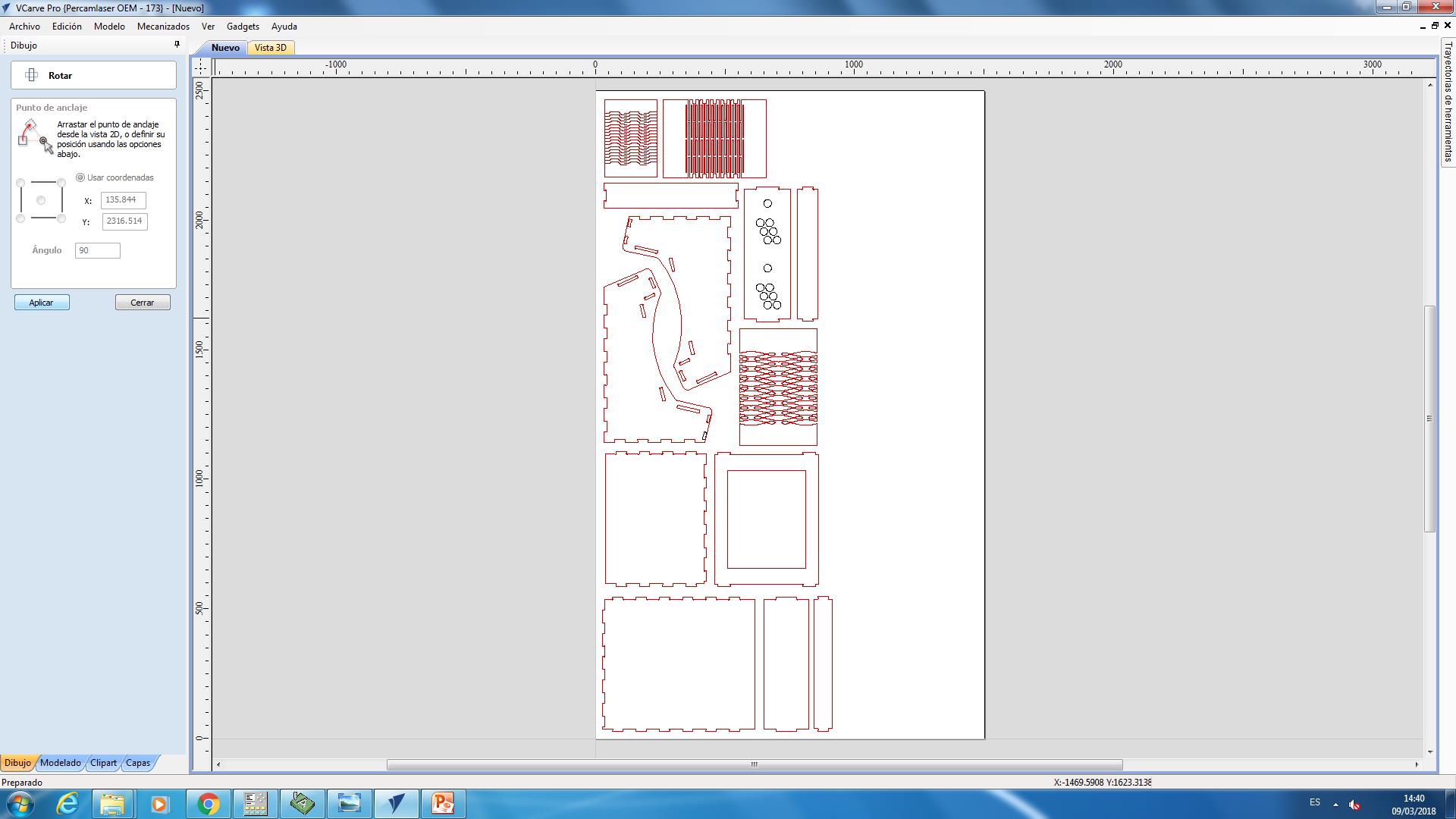
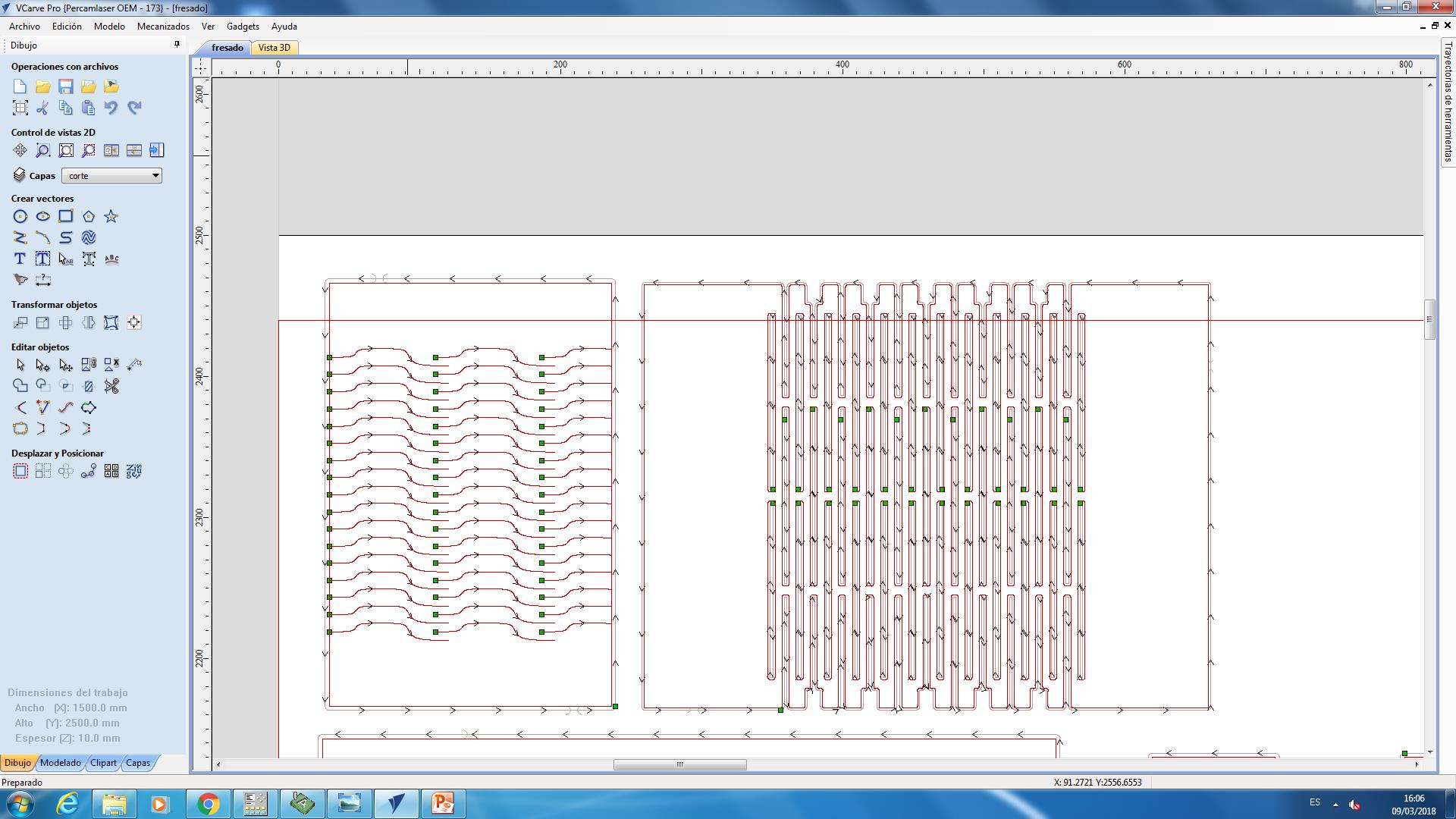
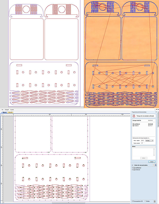
8. Begin to create work trajectories.
We have to think what will be the best operation correlation and which lines will be made in the same way with the same tool/milling cutter. We select these similar lines:
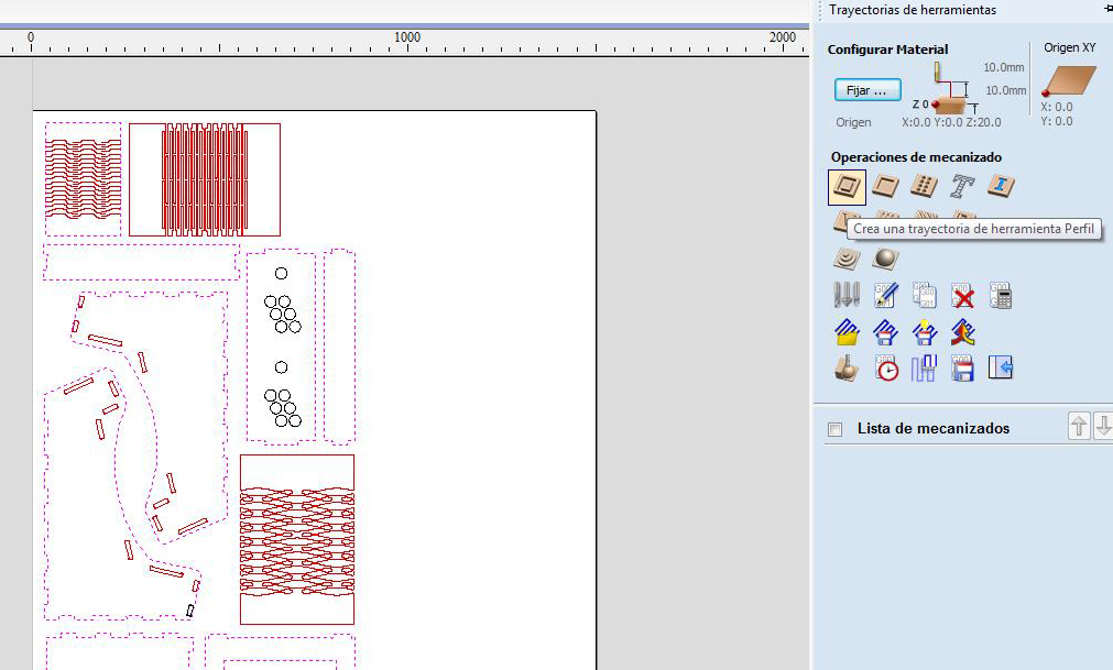
And we have to select which type of work, toolpath operation, we are going to do with them.
There are various types of toolpath operations, the most common ones are:
• “Perfilado”: Profile Toolpath.Profile Machining is used to cut around or along a vector. • “Grabado”: VCarve Toolpath.
This icon opens the V-Carving Toolpath form which is used to specify the type of carving required, tooling details, cutting parameters and name for the toolpath. • “Cajeado”: Pocketing toolpath.
This option opens the Pocket Toolpath form for machining 2D pockets. • “Taladrado”: Drilling Toolpath.
Drilling allows the centers of selected closed vectors to be drilled to a specified depth.
	9.	We choose first lines group and Profile Toolpath and:
			•	Cutting Depths (“Profundidades de corte”)
					o	Start Depth (D): Specifies the depth at which the Profile toolpath is calculated.
					When cutting directly into the surface of a job the Start Depth will usually be 0.
					If machining into the bottom of an existing pocket or stepped region, the depth of the pocket/step must be entered.
					o	Cut Depth (C): The depth of the profile toolpath relative to the Start Depth.
			•	Tool (“Herr”): Clicking the Select button opens the Tool Database from which the required tool can be selected.
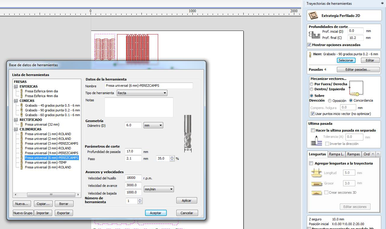
• Machine Vectors (“Mecanizar vectores”): There are 3 options to choose from to determine how the tool is positioned relative to the selected vectors/s. o Outside: Calculates a profile toolpath around the Outside of the selected vectors.o Inside: Calculates a profile toolpath around the Inside of the selected vectors.
o On: Calculates a profile toolpath On the selected vectors.
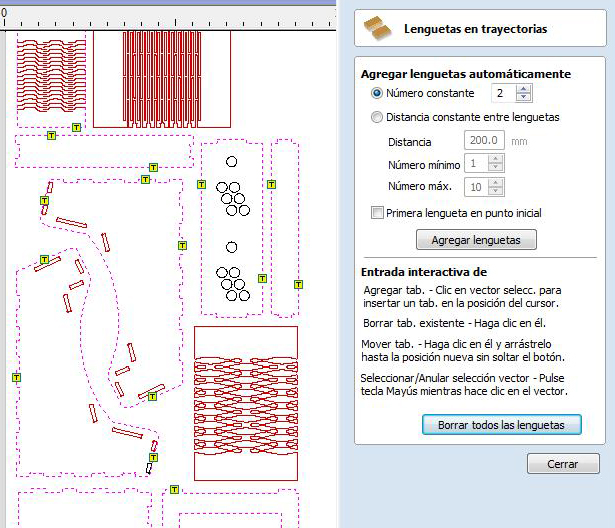
• Tabs, Bridges (“Lengüetas”): Tabs are added to open and closed vector shapes to hold parts in place when cutting them out of material. Checking ✓ the Add tabs option will activate tab creation for this toolpath. The Length and Thickness specify the size of each tab. And then Interactive Tab positioning is very easy. Simply place the cursor at the point where the Tab is required and click the Left mouse. To Move a Tab, Click and Drag with the Left mouse button on a Tab to move.
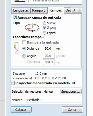
			•	Ramp (“Rampa”): Ramp moves are used to prevent the cutter from plunging vertically into the material.
			We have to Check ✓it.
			•	Order (“Orden”): The order tab allows you to specify the approaches the program will use
			to determine the best order to cut your vectors. We choose Vector Selection Order,
			in this way we choose manually the order of different parts machining.
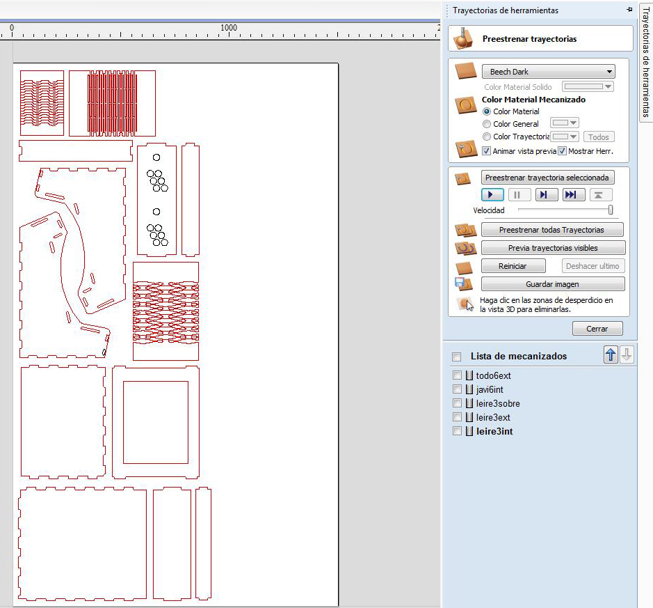
10. Calculate each trajectory.
In this first use of the milling machine we have made all with Profile Toolpath, cause all of them all are cuts: some with 6mm end mill, others 3mm end mill, outside, on or inside vectors, ecc.
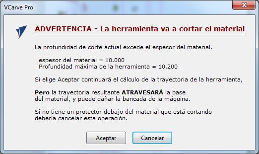
And, when we send each trajectory to calculate, VCarve said to us that there was something wrong or to take a sight in.
Material is 10mm depth, and we said to VCarve to go Z down 10,2mm. But it is right, we do it to ensure we are cutting side by side, and we have a wood sacrificial table.
I have done it with Javi, while our instructor was explaining every concept, and we have had 5 trajectories, where we have combine his and mine file similar trajectories.
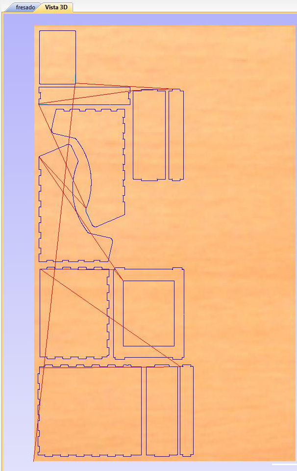
We can view each trajectory in 3D too:
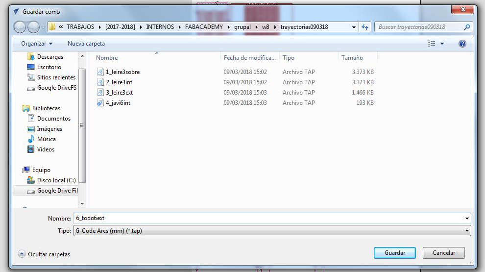
11. Save each trajectory in the correct Post-processor .tap file extension:
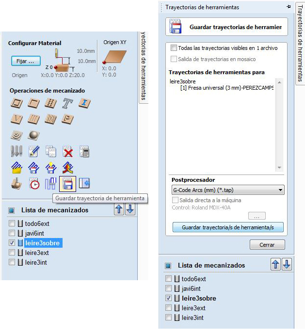
In our case we thought it was a good idea to insert numbers in file names, to know the machining process order easier, later in the milling machine.
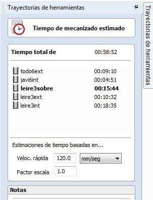
And milling process stimated time has been, totally, less than an hour. We have to take in account that it is theoretical time, due to tool changes and else VCarve doesn't calculate.
2_MACHINING PROCESS
		1. Insert .tap trajectory files in an USB memory key.
		2. Put material on the milling machine cut area.
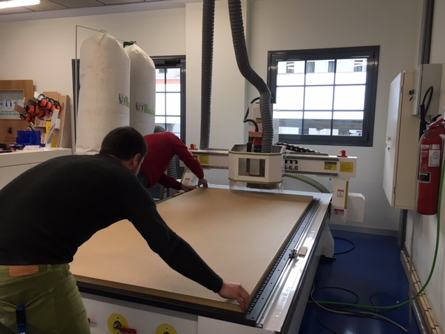
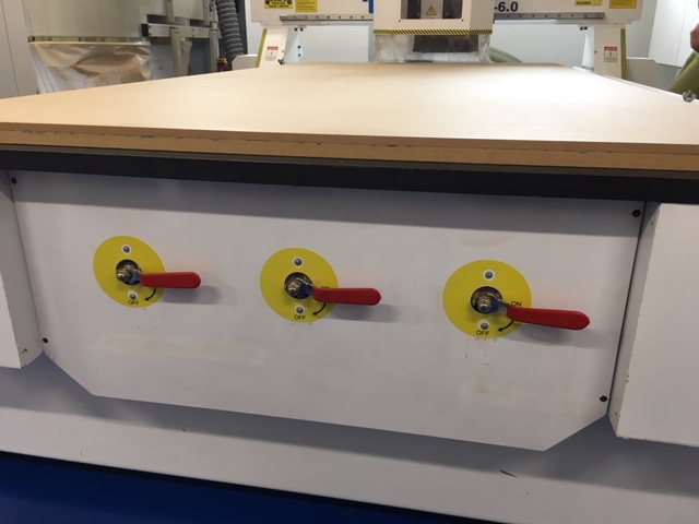
3. Select vacuum zones we need, depending material size.
In this case we are using all the work area, so we switch ON all three tracks.
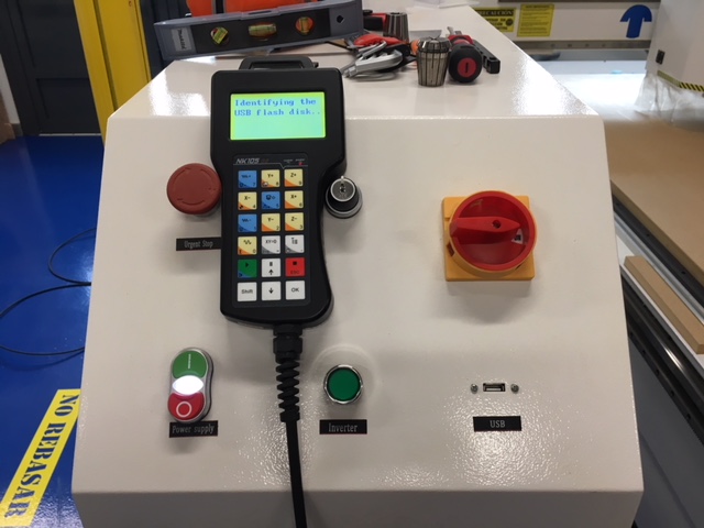
		4. Switch ON machine (using Power Supply green button.
		5. Wait while machine has been started, pay attention to the screen.
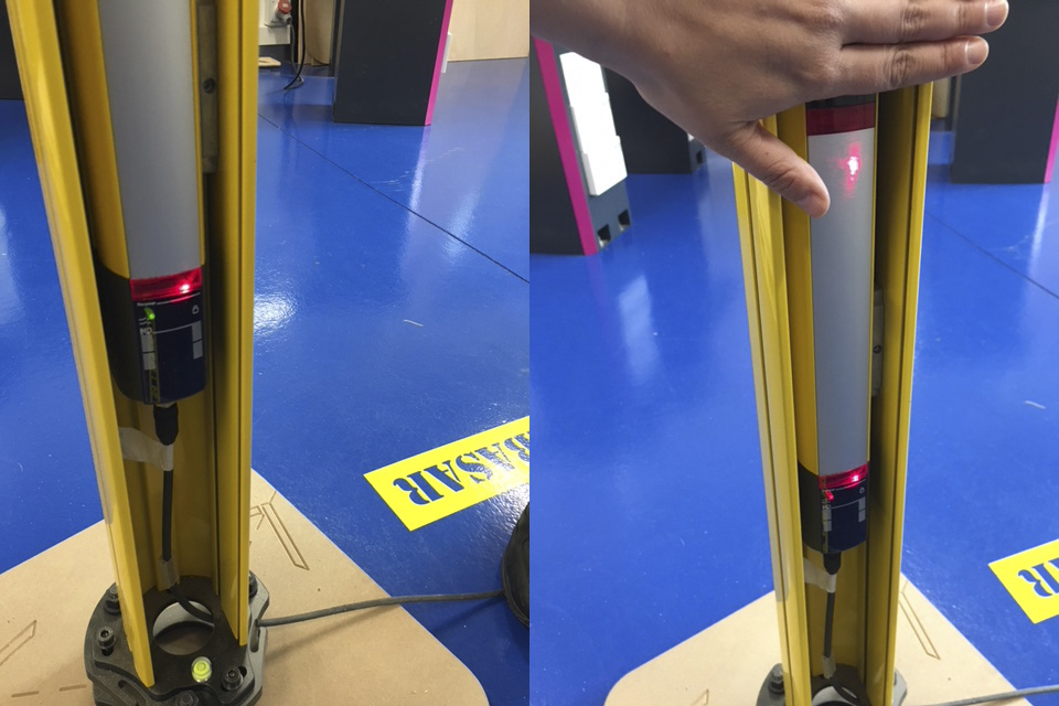
6. Be sure that the security bars are well connected.
In our case they have optical laser linkage, if it is well connected, the small light (see images below) would be green, if we pass security area light turns red and the machining process would be stopped.
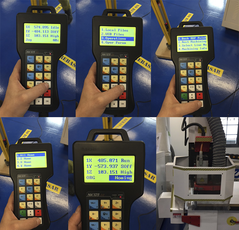
7. Home machine to its origin.
It would show us where the (X0,Y0,Z0) is in this moment. It is necessary before configuring our work origin.
The process is, using hand held control unit: Menu/3.Operations/1.Back REF Point/1.All Home/OK.
Machine will go automatically to its home.
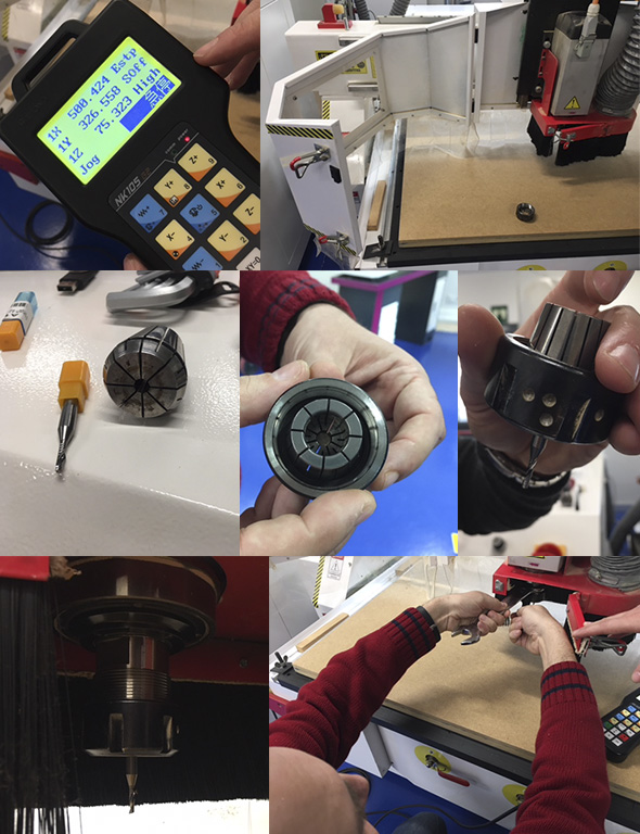
		8. Move, using hand held control unit, machine head to an inner zone.
		9. Prepare end mill needed with machine head and collet.
		10. Manually first, helping us with tools later, put in the end mill.
In the hand held control unit will appear something writted in japanese, it means that security control has stopped the machine. Well.
Collet diameter would be the same as Shank Diameter of the end mill selected.
When we have fixed the end mill into the machine, it is good to switch on and off the machine, and check the union once, to ensure that it is totally fixed.
		11. Configure our x=0 and Y=0.
		12. Configure our Z=0 using sensor detection.
To configure (X,Y)=(0,0) we have to use hand held control unit, move machine head to our zero (in this case down-left) and say it is our XY origin.
To configure Z0 we have to go onto material and situate the sensor just down the end mill, and using hand held control unit say to detect it.
		13. Insert USB memory key with trajectory files in the machine.
		14. Switch ON two machine Vacuums: Superior and inferior.
		15. Send each file to machining, one by one. And change end mill when it is needed.
To send files go to Menu/USB files/, then select clicking OK and send it to machine clicking in button 1.
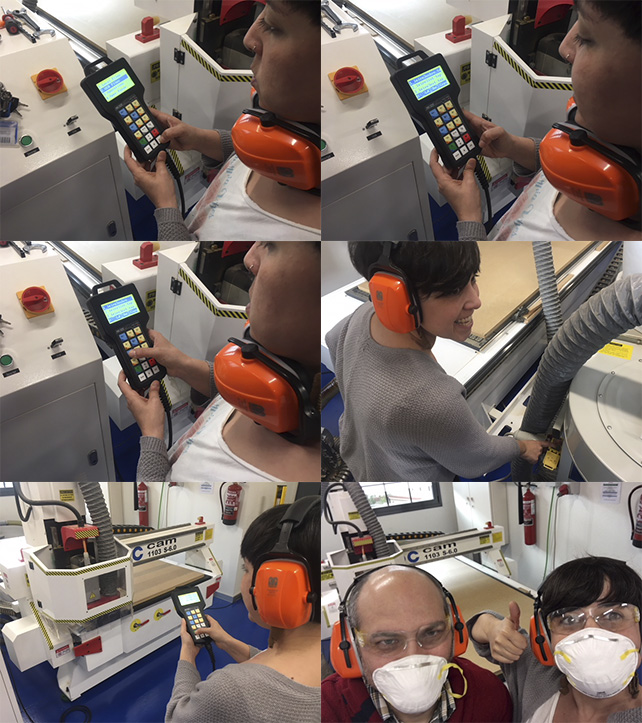
IMPORTANT! Before send files to machining, it is important to wear security glasses and earphones! Then, click PLAY button.
FIRST MACHINING RESULTS
*Files for this first machining trial here.
For first time using this machine I wanted to benefit time doing something that would be useful for my final project. So, I made Living Hinge proofs that I have made first in Laser Cut. I needed to test them with bigger material thicknesses for my smart urban garden structure and pot-supports.
I had its designs done, conbining SolidWorks and Rhino, since I did Computer Aided Design and Computer Controlled Cutting. I only took them and modified them to make the following tests, using Rhino.
And...I have had some problems and learnings this firs time!
		- First of all, when we have configured material dimensions on VCarve,
		we have introduced work table dimensions, not material dimensions!
		So, some of my parts went outside material.
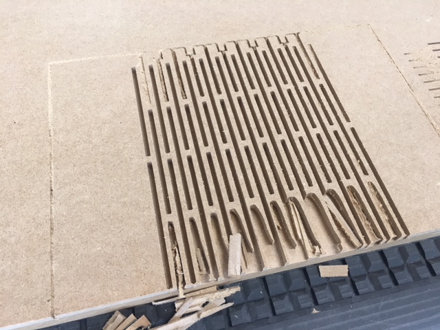
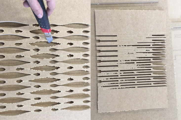
		- Second problem, we have introduced 10,2mm Z down for ensure cutting well material,
		but maybe due to work table dirt, it doesn't cut it completely.
		I have had to clean it with a cutter.
		- The third has been more a theoretical learning:
		I have made 3 different Living Hinges,
		and the first one in the image below has been broken.
		> The other two worked well! :)
SECOND MACHINING RESULTS
*Files for this second machining trial here.
For first time, I take advance to make test about these Living Hinges just in Smart Urban Garden parts.
I have use one Living Hinges, in different widths, in the Small Pot-Support design.
I have used the other Living Hinge in the Structure of the vertical garden, but as it is only a first test, minimizing its size to the minimum.
As I have had Structure and Pot-supports, I have the opportunity to test Joints between them too.
I followed the instructions from the first part to make it, using always 3mm end mill, due to structural cuts dimensions.
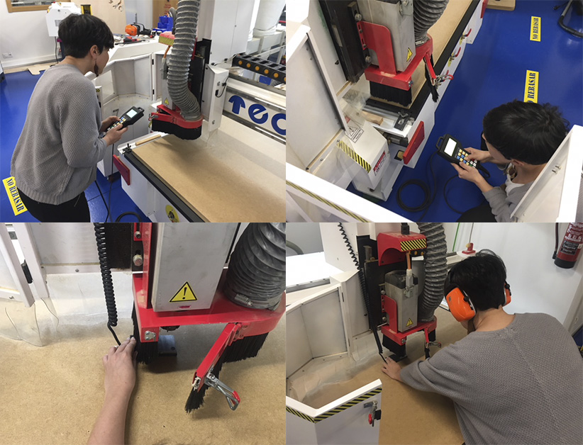
You can see here milling machine working, and the noise it produces, it is important to be safe! Use security earphones!
And...I have had some problems and learnings this second time too!
		- The width of Living Hinges is very important, and I didn't take it in account.
		- I have to modify design files to make more tests of folding.
		- DM is not the best material for Living Hinges, and it is not very resistant to humidity.
		- Joints are easy to assembly, it is good.

		So:

		- I have to make a third trial with Plywood.
		- I have to modify Structure and Pot-support designs to play with Living Hinge widths.
THIRD MACHINING RESULTS
*Files for this third machining trial here.
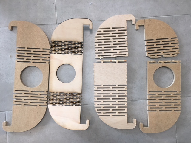
I took pot-support and I changed some dimensions: In general, the width of the Living Hinge. But this time I decided to make a small and a large pot-support, and test the folding of two sizes.
And, I changed material, this time I used Plywood.
Third trial, and I decided that it is not a good idea doing small pot-support by a milling machine:
		_ its dimensions are too small to get Living Hinge width needed,
		_ and if we analyze design needs: it will support only small flower-pots,
		so it is no needed a big thickness in the material.
Small pot-supports will be made by Laser-Cut, 5 mm thickness plywood. I made some test to improve dimensions too.
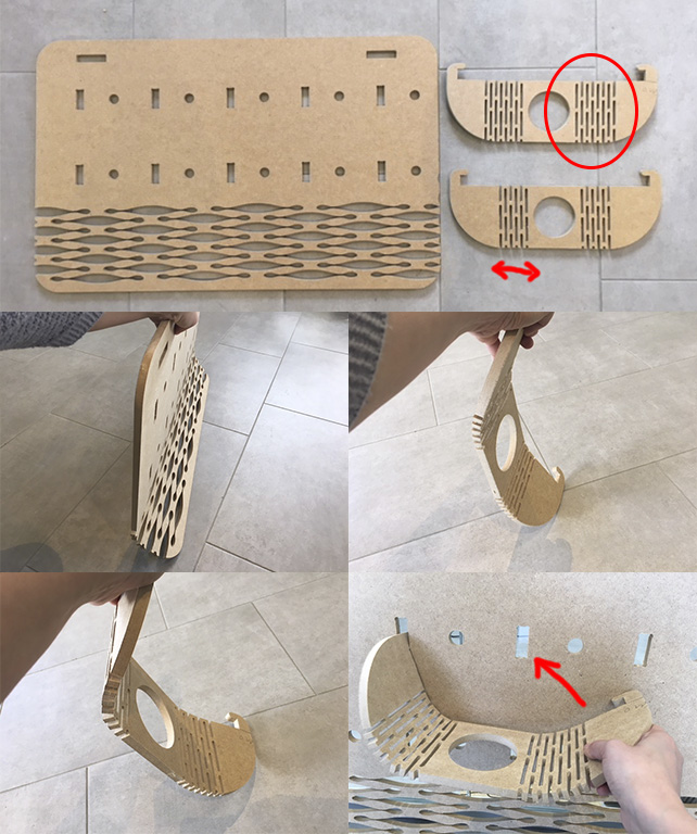
In the next image we can see: Not foldable CNC-milled DM piece, foldable Laser-Cut plywood piece, and broken CNC milled plywood and DM pieces.
In the image below we can see how big size pot-support can be made and folded by CNC-milling machine, and how small and big supports are folded and mounted in the structure test.
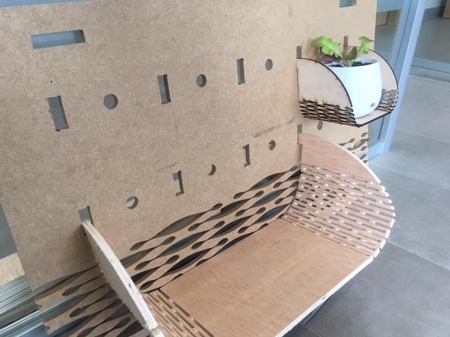
Next steps:
		_ Change Structure design for allowing only small pot-supports in the upper side of the smart urban garden.
		_ Improve joints between structure and supports, both laser and CNC pieces.
DOWNLOADS
_ 1st machining files (DXF and .TAP -trajectories-)
_ 2nd machining files (3DM, DXF and .TAP -trajectories-)