Exercise 04. Computer Controlled Cutting
Situation
After the lesson about VinilCut and Laser-cut Machines on Wednesday 07 February, the assignment for this week was to:
			_ group assignment:
				- characterize our laser-cut machine in Deusto FabLab, making test part(s)that vary cutting settings and dimensions.
			_ individual assignment:
				1- cut something on the vinylcutter, something like an sticker to my computer.
				2- design, lasercut, and document a parametric press-fit construction kit, accounting for the lasercutter kerf,
					which can be assembled in multiple ways.
				3- make something related to my final project using Computer Controlled Cutting technology.
GROUP ASSIGNMENT
My FabAcademy mate is Javi Vicente in Deusto Fablab, and we have the pleasure to work with the EPILOG Laser FUSION CO2 75 Watts Machine.
This machine allows us to cut and engrave different material, always "soft" materials, which can be woods, PMMA, cardboard or leather, among others (but never PVC, be careful due to its toxicity). Its work maximum area is about 800x500 mm, and we can work in it with two CO2 laser lens, which are replaceable. We call them short and long lens, and normally used is the short one.
The works we can do are cut and partial cut in Vector operating mode, and engraves in Raster mode.
As we have several types of material in the laboratory, comes well to have samplers and one of the work to do is to try different settings, we have made the following DM engrave sampler (prepared first in Rhinoceros):
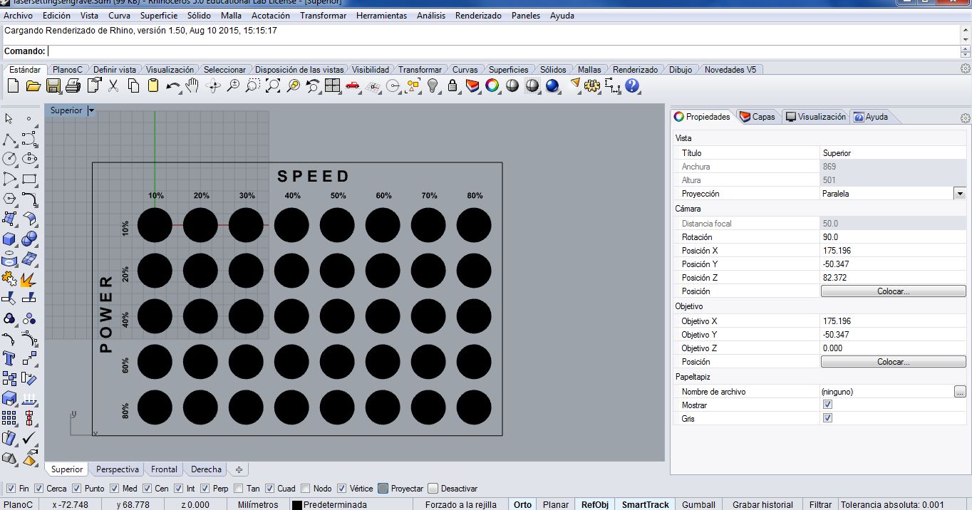
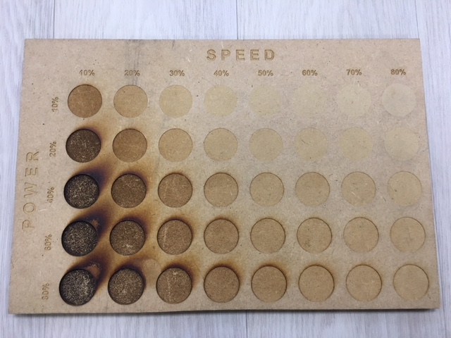
We know that this setting are just for that material piece today (due to its humidity and hardness), but the idea is to create samplers to all materials we have, over time. We think is good to have an idea around what values we can begin to make tests when we are going to use the laser-cut machine in the future.
You can find the complete files (.3dm and .dxf) here.
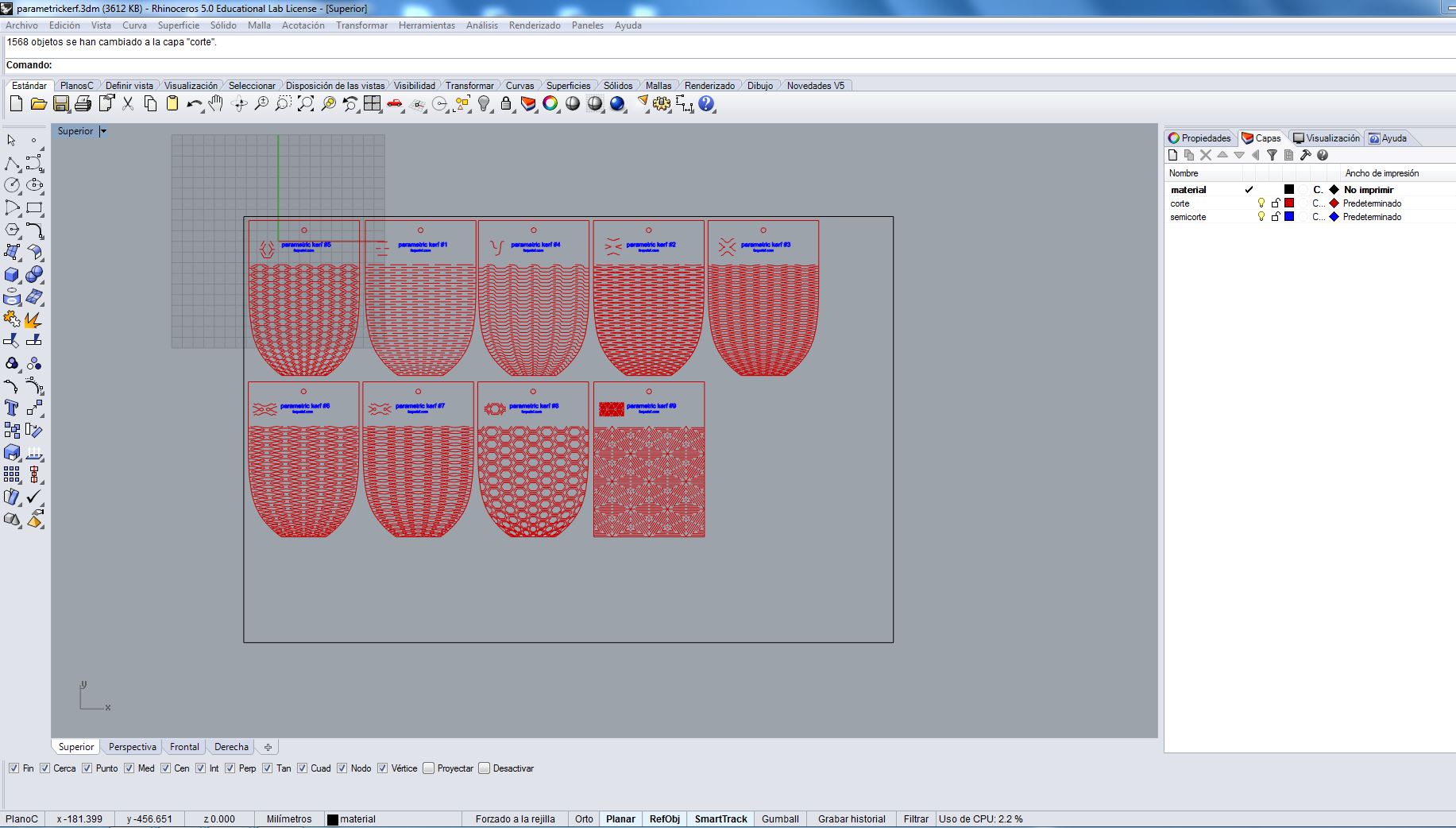
On the other hand, I commented in the Exercise 3 my interest in Parametric Kerf Templates, and we think that is a great idea to have these samplers too in our FabLab, so we have made them in the laser-cut machine. You can see below the complete process:
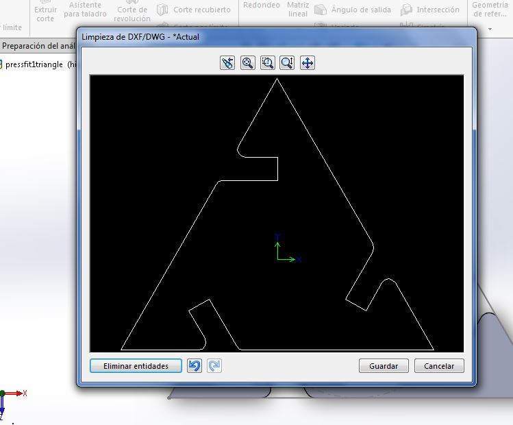
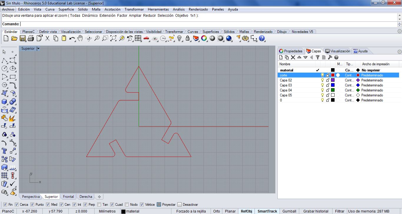
First of all we took the .dxf file we found hereand we prepared it by layers to be able to send the different works to the machine: Cut (red) and Partial Cut (blue). The other layer we had to create has been Material (black) one, with No Print setting, to help us centering the designs in the material we have. See the image below:
We send the Partial Cuts first. For woods is better to do first this kind of works (like engrave) due to the machine Kerf. When we "cut" with the laser the material is volatilized, and remains a gap between the cut pieces (kerf), so that with the movement of the subsequent works they can be moved, and we are not interested on it.
The values we used to this work are: Vector, 60 Speed, 30 Power and 85 Frequency.
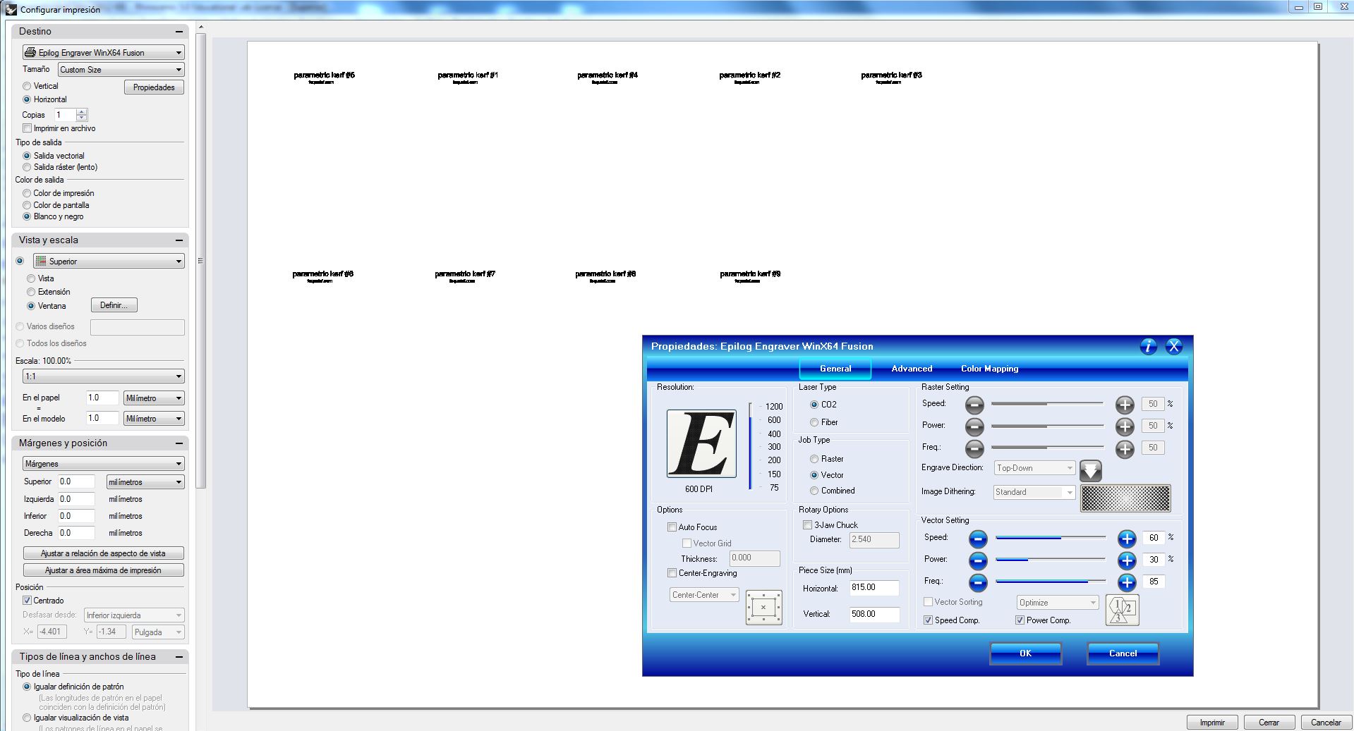
The values we used to cut, later, are: Vector, 8 Speed, 90 Power and 85 Frequency.
Its important to prepare the origin of the machine (0,0,0) in the place we have defined it in the digital file, so we have to make the focus (set the Z axis in 0, to focus the laser to the surface of the material to be etched/cut) and the Jog (X and Y axis in (0,0), up-left corner in our case). For all these settings we have the command screen with a Joystick in the Epilog Laser Machine.
Close the machine door, switch on the fans and GO with the works!
After finishing the Cut work is good to check if the pieces are well cut, but carefully not moving the different parts, because if we have to repeat the operation we need it just in the same-same place.
In our case the edges were well cut but maybe too much because they are so burned. :S
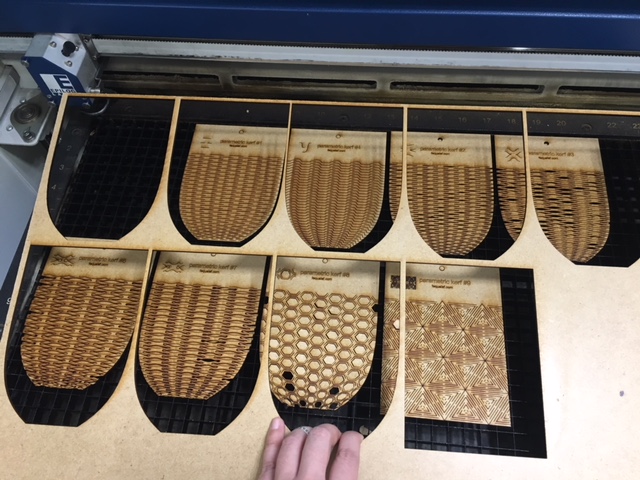
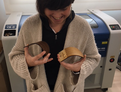
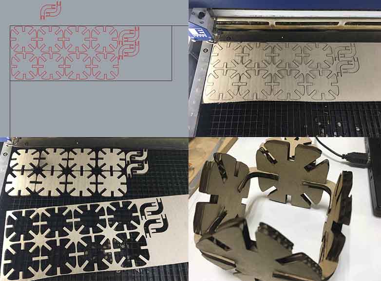
In the two images below you can see the 9 Parametric Kerf Templates made in 3mm thickness DM wood, and me testing them and having fun with it!
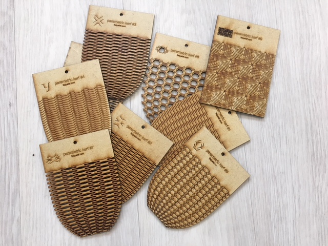
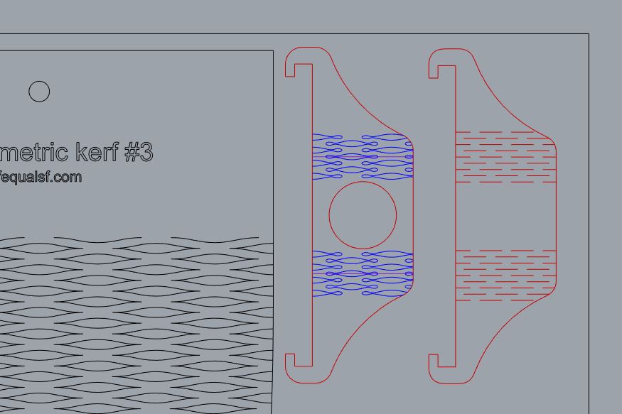
In these days we have found another Parametric Kerf Templates, Living Hinge Swatches (see the image below). We have prepared the Rhinoceros file with all layers to made them in the laser cut machine when we have more time. Work to the future!
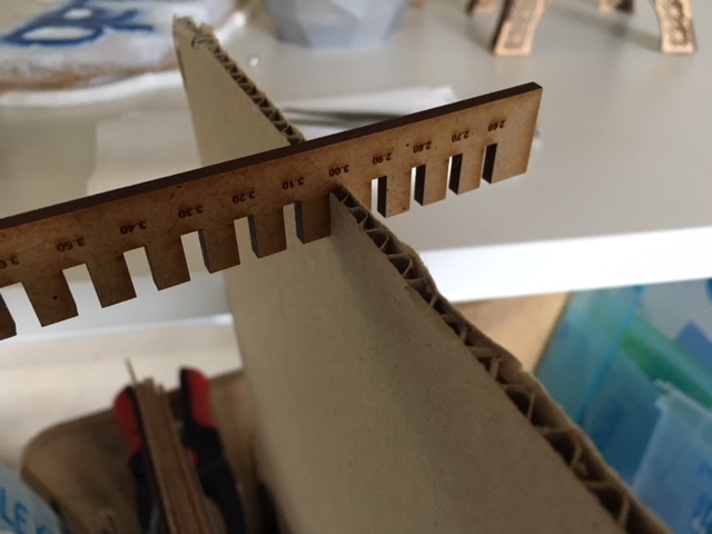
In the other way, we have created some thickness gauges, during the group assignment, see a sample image below:
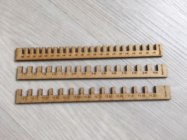
They will be very useful defining the press fits for our future designs. For example, you can see below press fit test to a 3 mm cardboard:
To see the complete files (.3dm and .dxf) click here:Parametric Kerf and Living Hinge Swatches. And for thickness gauges here.
INDIVIDUAL ASSIGNMENT
1_ VINILCUT
A vinyl cutter (or vinyl plotter) is a computer-controlled plotting device with a blade instead of a pen. A vector based design is created in a software program (usually Adobe Illustrator or similar) and then sent to the cutter where it cuts along the vector paths laid out in the design. The knife moves side to side and turns, while the vinyl is moved beneath the knife. The results from the cut process is an image cut into the material. The material is then 'weeded' where the excess parts of the figures are removed from the release liner.
For this exercise we are using adhesive vinyl, so finally a sheet of transfer tape with an adhesive backing is laid on the weeded vinyl. The transfer tape and the weeded vinyl is pulled off the release liner, and applied to a surface. When we pull the transfer, the vinyl will be sticked in the surface.
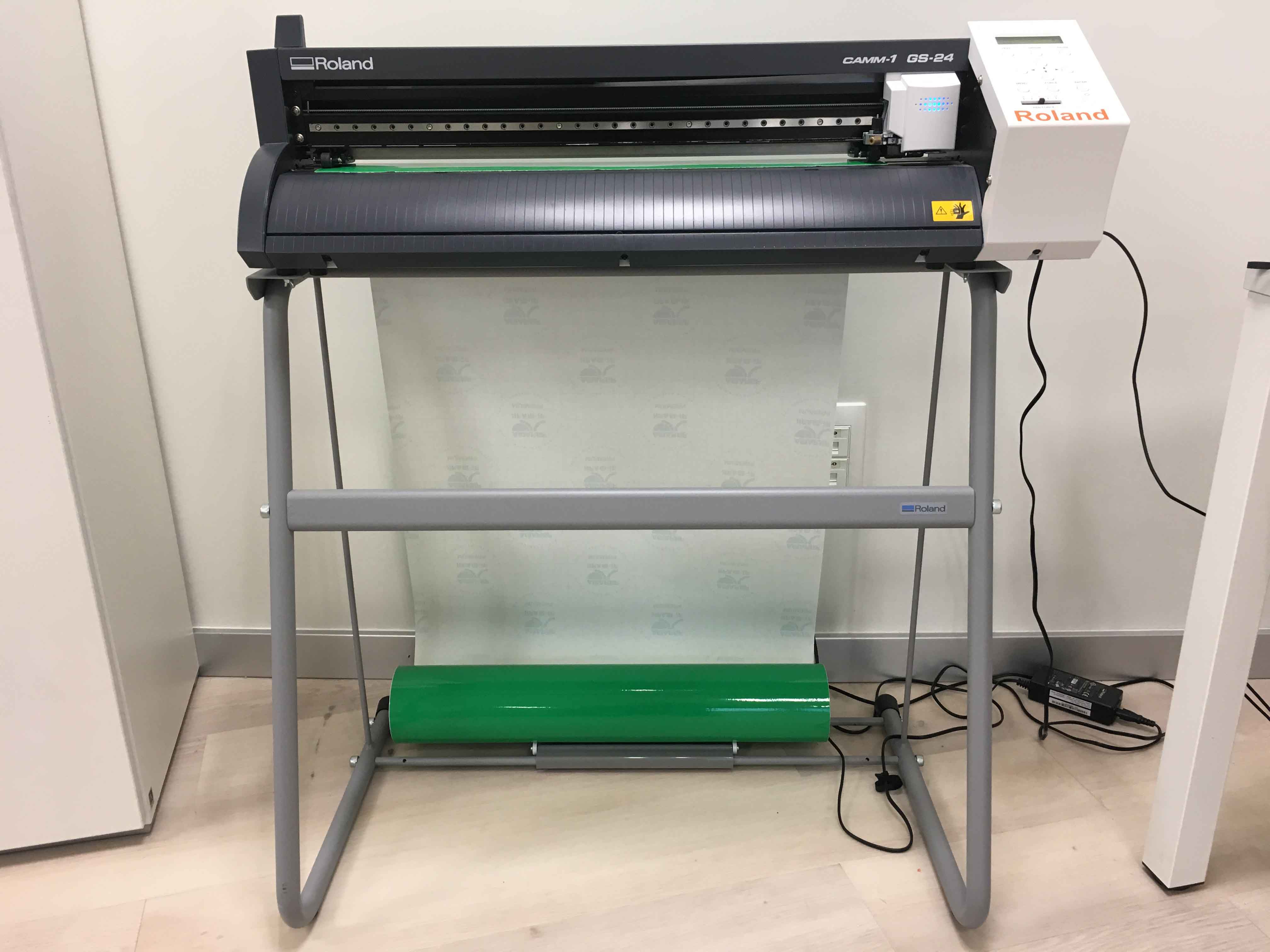
In Deusto Fablab the VinilCut Machine we have is Roland GS-24. Its maximum cut area is about 584x25000 mm, it can cut materials with thickness below 0.5 mm and it has an optical sensor which allows us to see the proper placement of the piece of material in the machine. The Force and Speed are specified in the machine menu just to be able to cut all the vinyl materials we have in the laboratoy, but we have to make tests and change them if its needed in the case we carry a new material. The parameters it has now, predetermined, are speed 20 m/s, power 20gf and offset 0.25 mm.
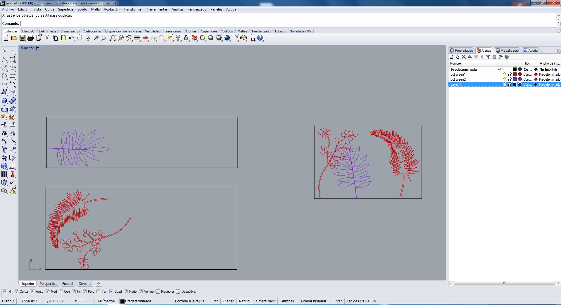
I have designed some leaf in Illustrator, simply, to dress my laptop. I export them in .dxf and put in Rhinoceros to send and cut them in the Vinyl Cut machine:
I used a vinyl roll and I put it in the machine as you can see in the image below:
The material has been aligned using the guide lines it has (see the image below) and the white marks combined with two wheel blocks. Then, we have the material cut maximum area, in this case only in the X axis, saying in the screen menu that it is a roll (Selec.Hoja/Rollo):
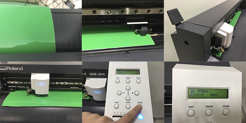
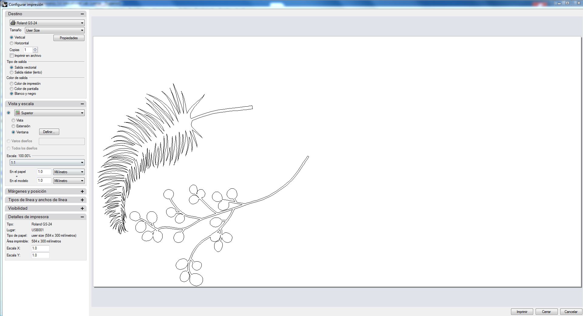
In the print configuration window (see below), we have to first get the Cut Area dimension from the machine (Propiedades/Get From Machine) and then center machine visualization onto the design we want to cut (Vista y Escala/Ventana/Definir). It is important to be sure about the scale 1:1, the file units and our design vector lines unity and continuity. It is very important not to be duplicate lines too, the machine has to pass only once through each vector.
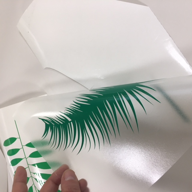
When the cut (print action) is finished, we have to delete all the parameters using the machine menu, and extract the piece of vinyl with the cut results. We take out now the excess parts of the figures, leafs in my case.
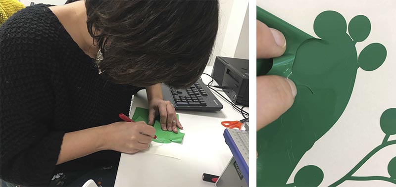
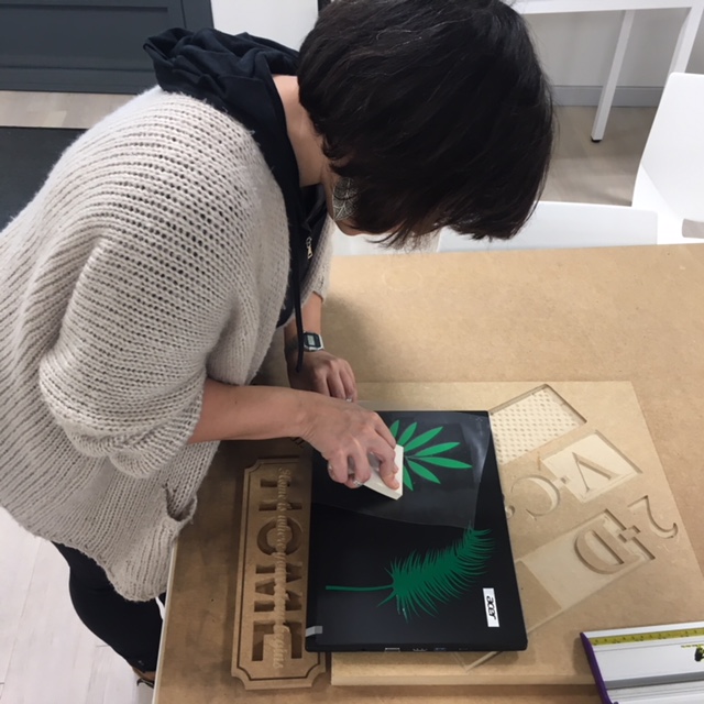
A sheet of transfer tape with an adhesive backing is put on the cleaned vinyl, helped with something flat to make press onto the vinyl part and be sure that the vinyl is going to be well stuck to the transfer.
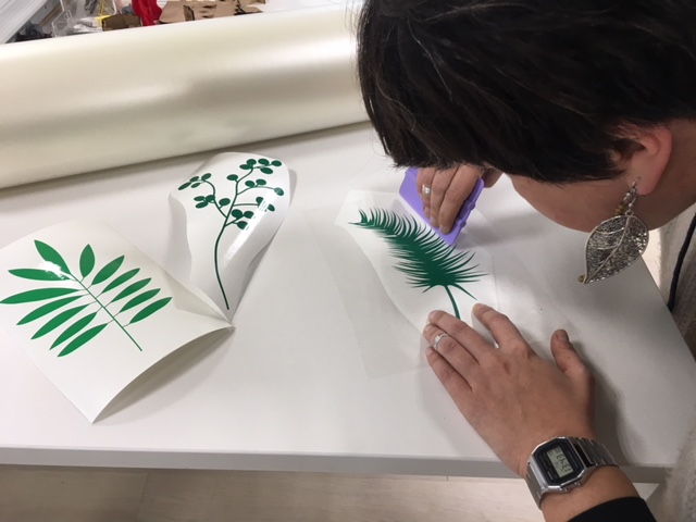
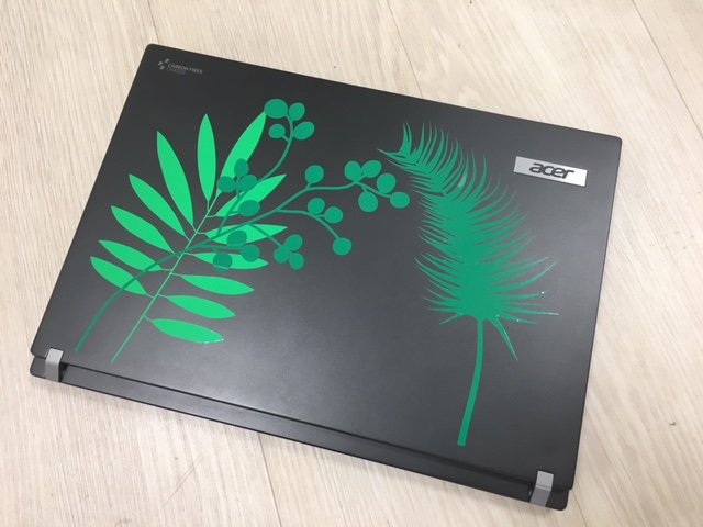
After it, I took the leafs one by one and I sticked them in my laptop, using a softer but flat piece to be sure that all parts of the leafs where sticking to the laptop surface.
Woala!
As you can see I had problems with the big-spiky leaf in the weeding phase: spiky parts were not easy to "clean" and finally I get a shorter leaf, but still beautiful as wild nature.
To see the complete files (.3dm, .ai and .svg) click here.
2_ PRESS FIT
An interference fit, also known as a press fit or friction fit is a fastening between two parts which is achieved by friction after the parts are pushed together, rather than by any other means of fastening.
We have to experiment with cardboard and Laser-cut creating some Press-fit parts. In addition, this parts have to be prepared parametrically, to adequate them to different material thickness easily.
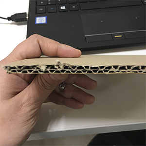
The cardboard we are going to use is 6mm corrugated we can see in the image below:
I have made two different Press-fits, A and B:
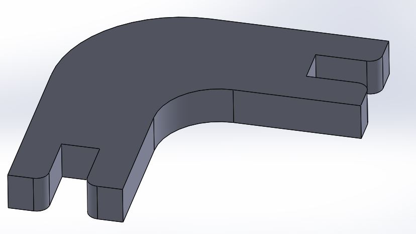
PRESS FIT A
This is a one piece design. Triangular one piece.
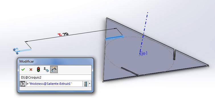
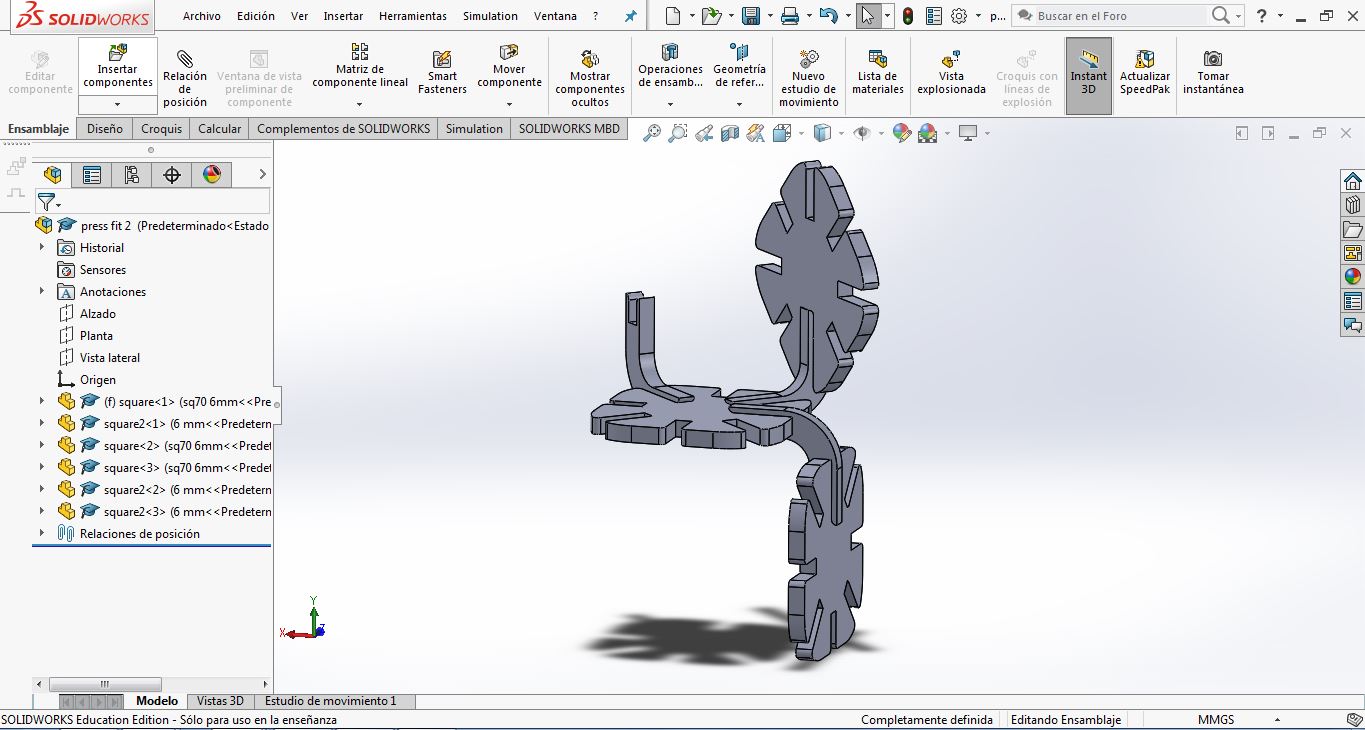
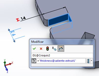
The design and parametrization has been made by SolidWorks, calling "thickness" to the dimensions related to the piece thickness and the width of the assembly guides. Theay are relaed, so if I change the thickness it will change the other too.
After choosing 6 mm thickness due to the cardboard we used, I exported it in .dxf to go to Rhinoceros. We use this to communicate with the Laser-cut machine.
In Rhinoceros I prepared the different layers for the cutting action (Cut and Material layers):
After preparing it with 10 repeated A pieces, I went to print menu and I set parameters to cut: Vector, speed 8, power 60, 90.
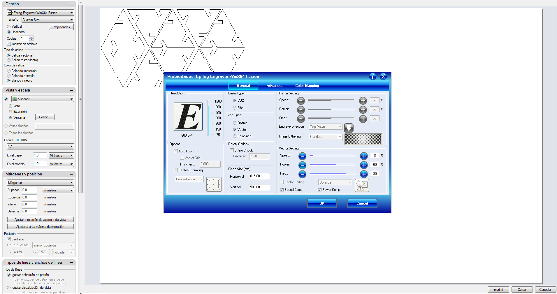
Put in the material, Focus the machine (Z axis 0), Jog (X and Y axis 0), close door, switch on fans an GO!
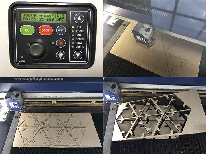
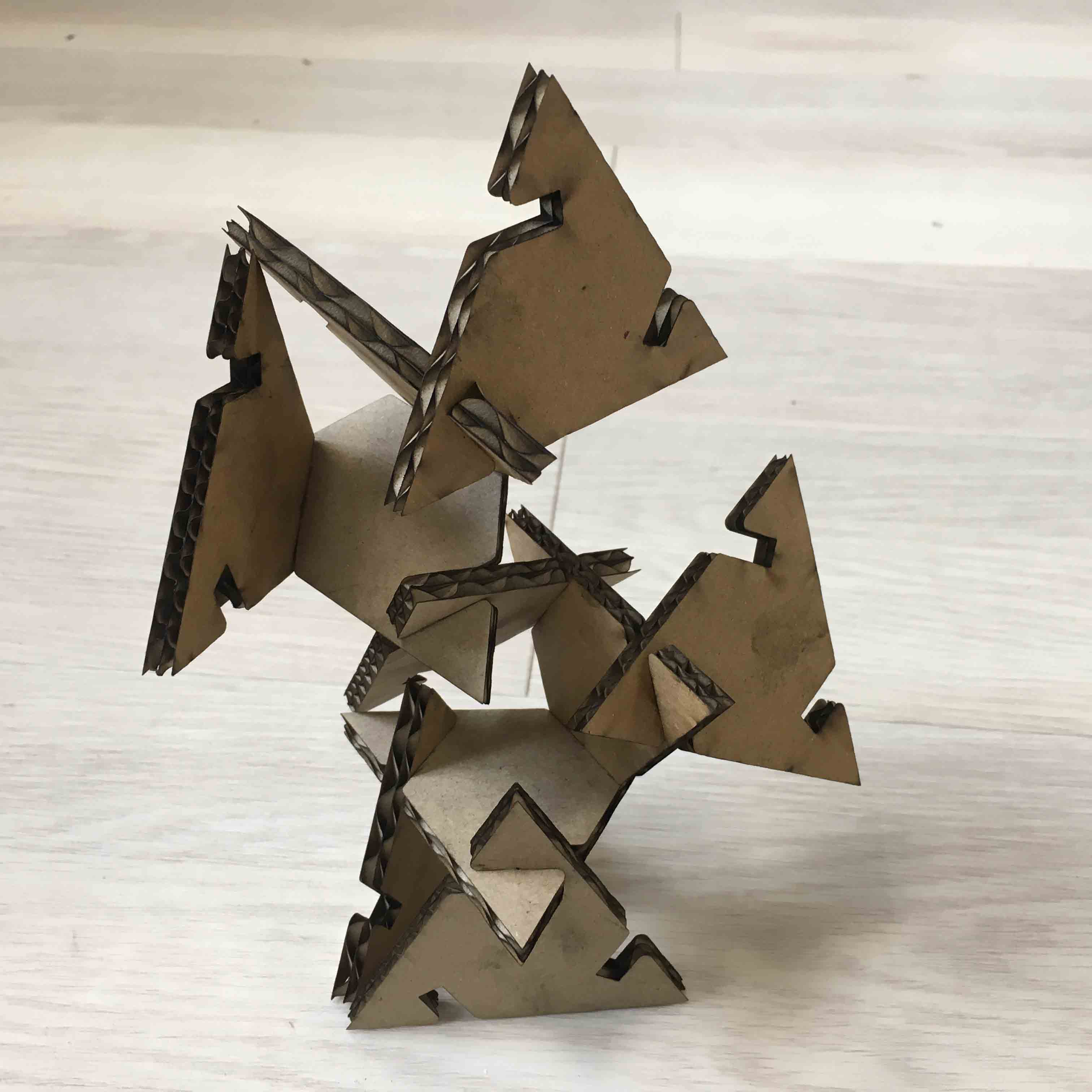
This is the final 10 A triangular pieces one of the assemblies option. :)
To see the A model .dxf files, for 6mm thickness cardboard, click here.
PRESS FIT B
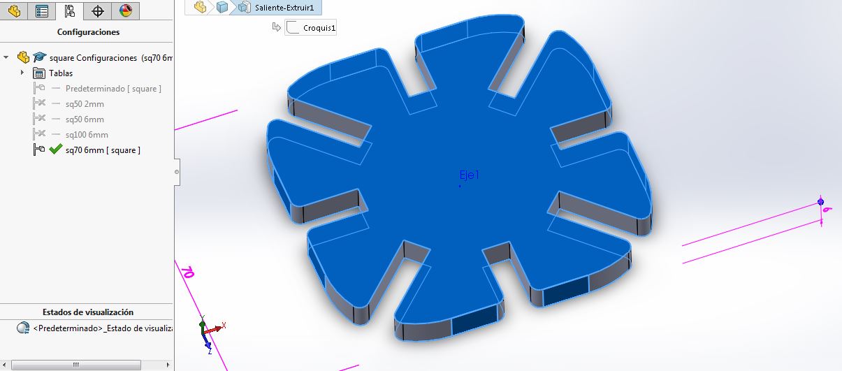
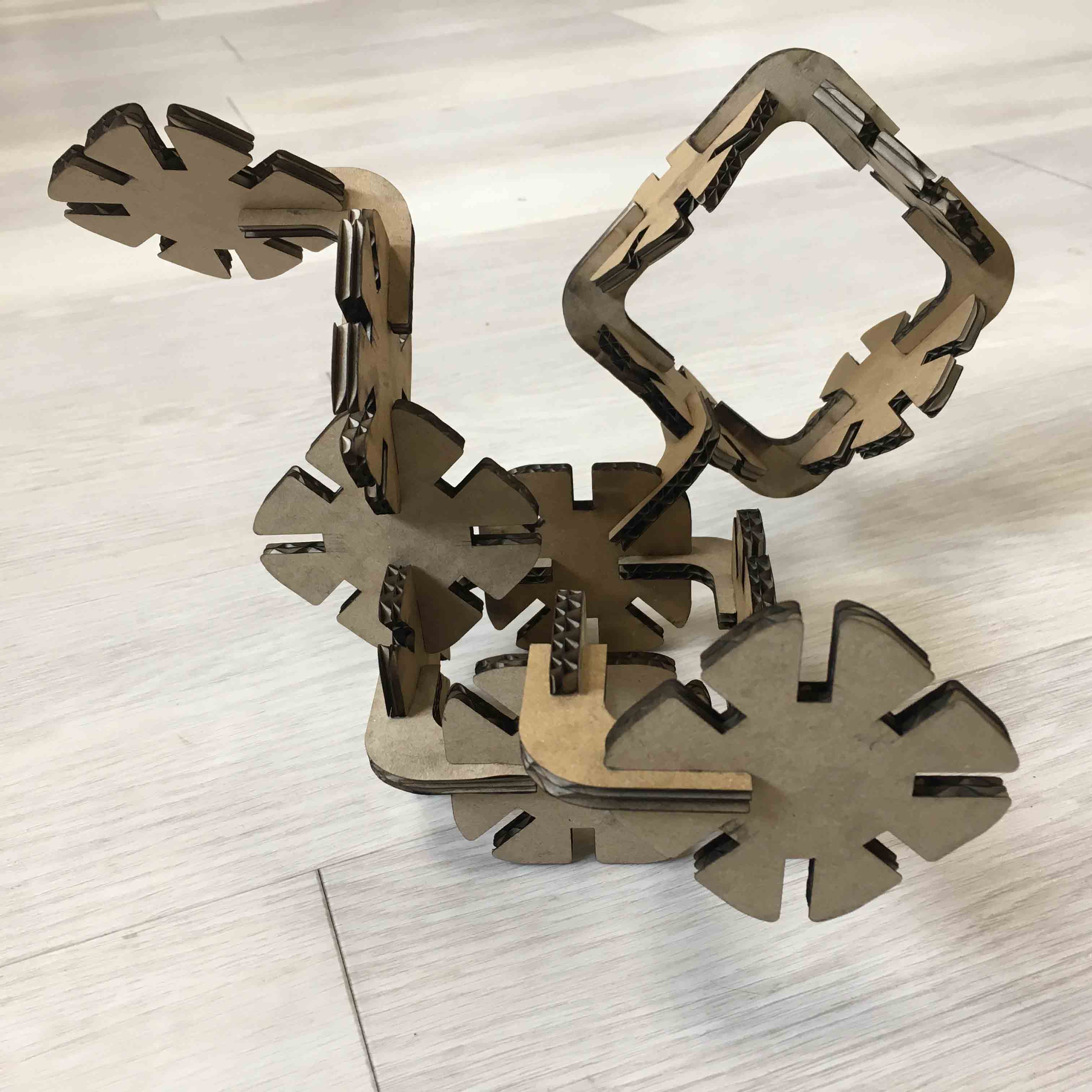
This is two pieces design. Square design.
The design and parametrization has been made similar to the A model, but in this case for two pieces:
The same parameters to cut: Vector, speed 8, power 60, 90. Put in the material, Focus the machine (Z axis 0), Jog (X and Y axis 0), close door, switch on fans an GO!
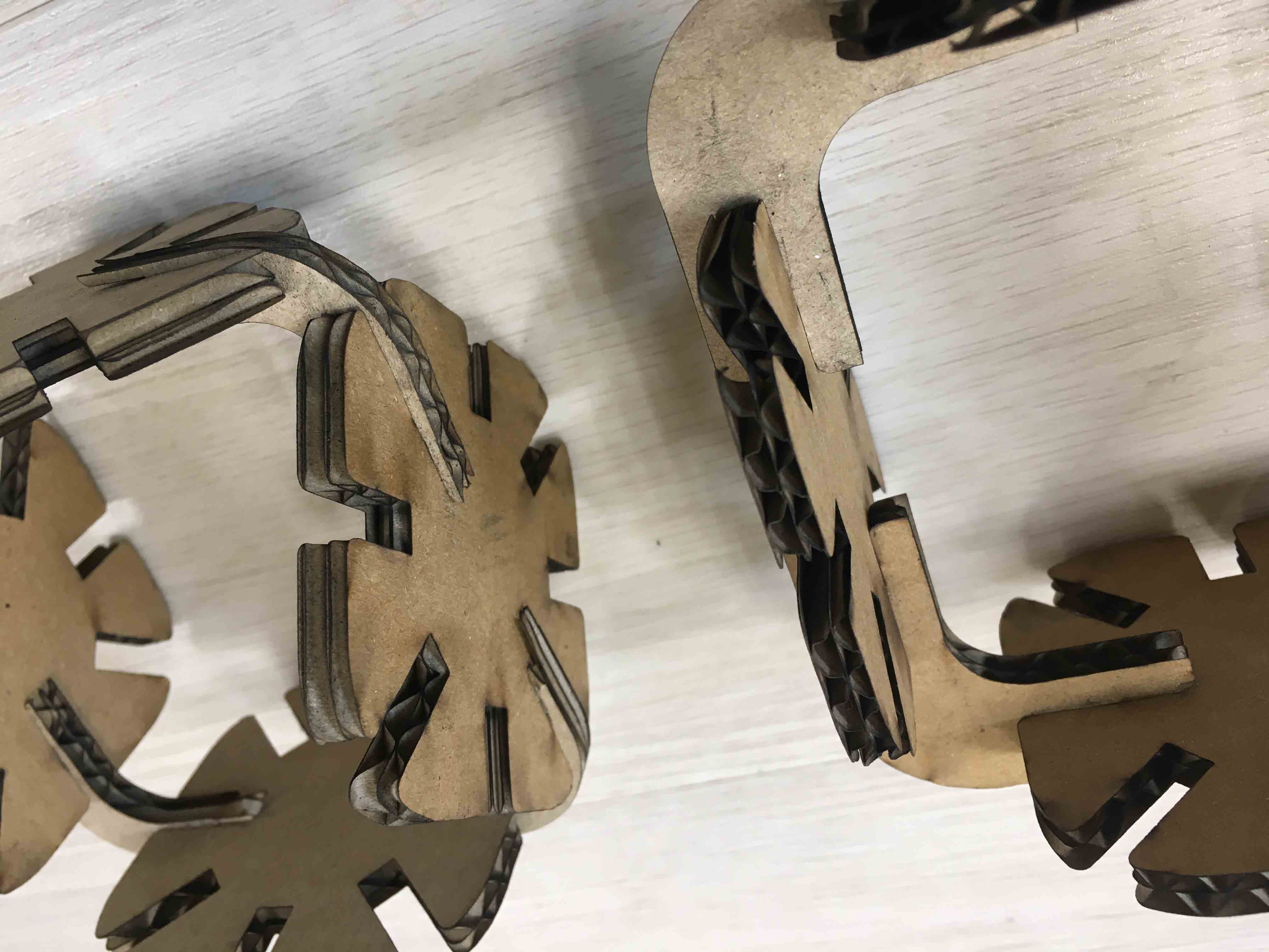
In this case I have had a problem with the Square2 design. It was so weak in the exterior part sides, they were not enough resistant to the fastening, so I changed the 3D and I parametrized this dimension too:
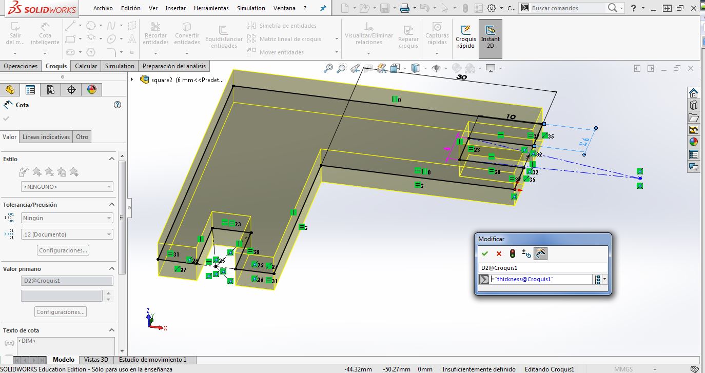
After making new ones I saw that it was good, and resistant. In the image below you can see the comparative between them:
And Woala!
To see the B model .dxf files, for 6mm thickness cardboard, click here.
To see the complete parametric files (Solidworks and Rhinoceros, .3dm) click here.
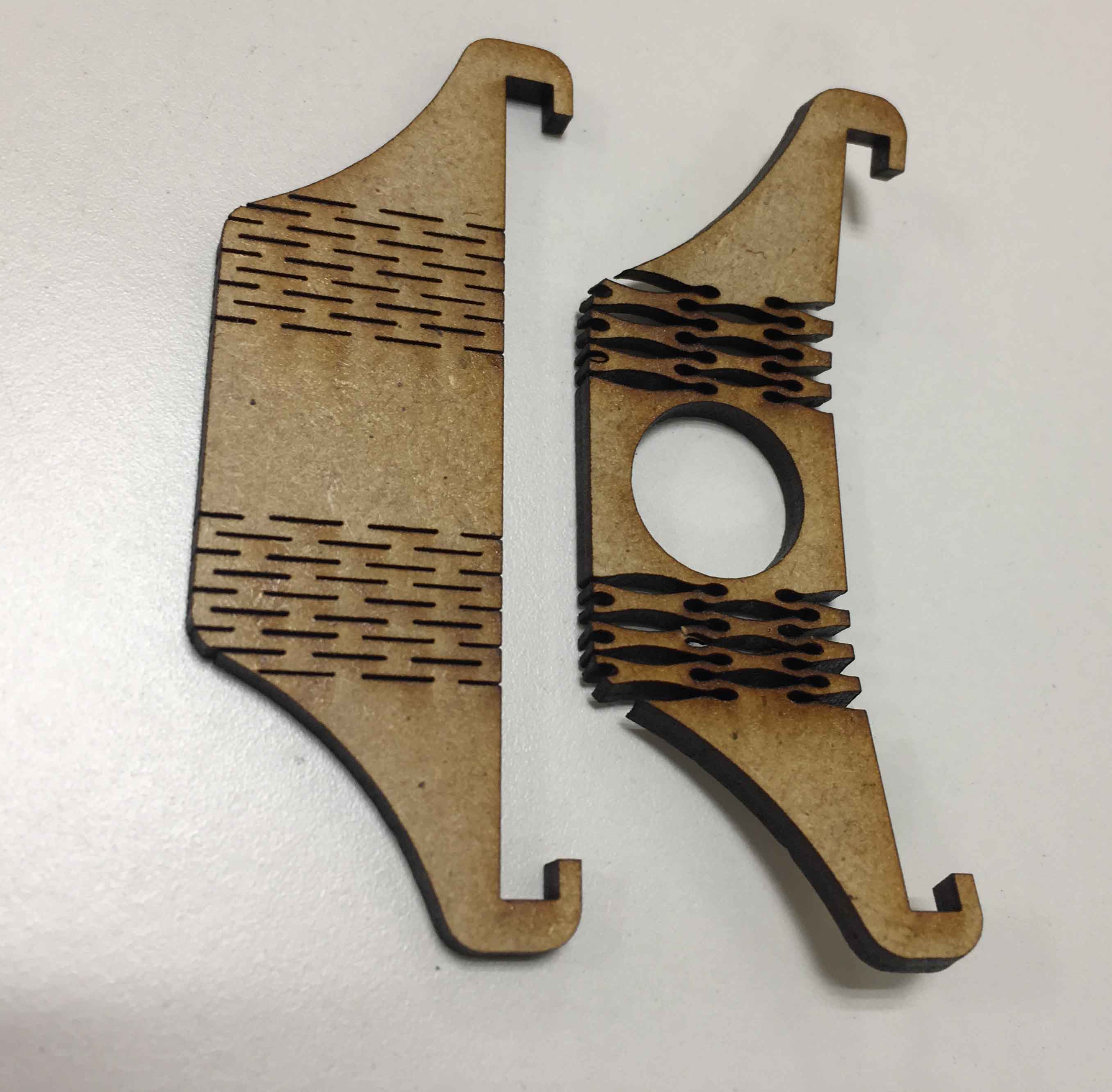
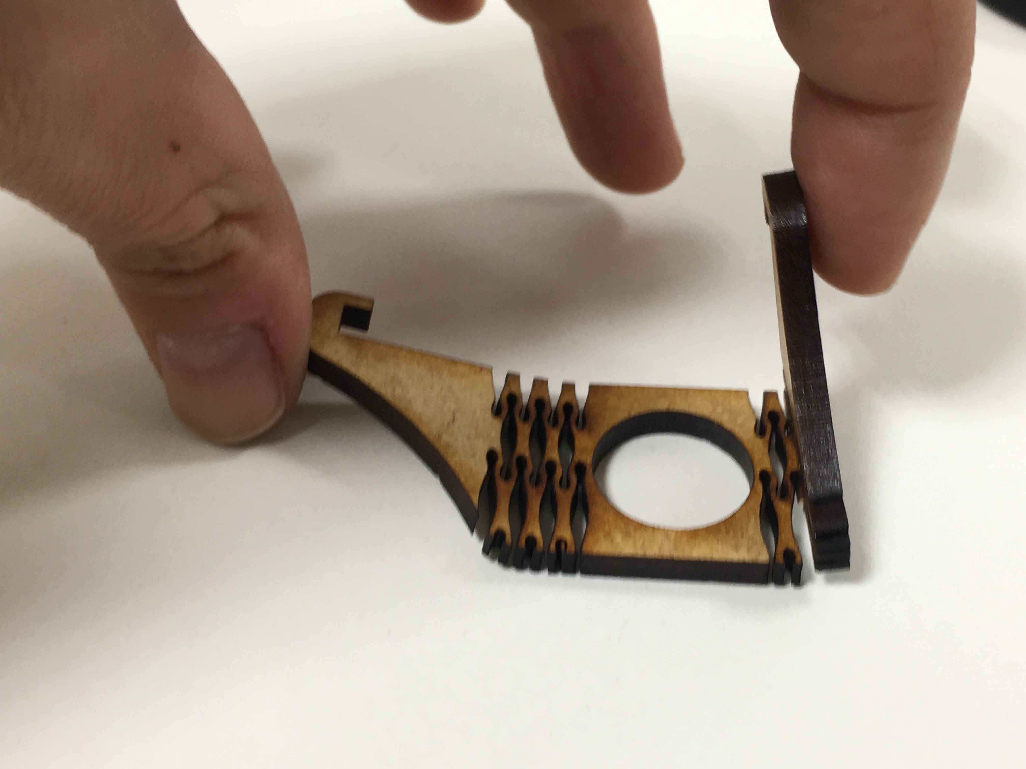
3_ FINAL PROJECT RELATED
And finally, I put my mind working in my final project. The foldable Smart Urban Garden!
The idea has been to create a small prototype to see how different hinge work in my parts, and then, to define exactly the press fit I need between the structure and the pot supports.
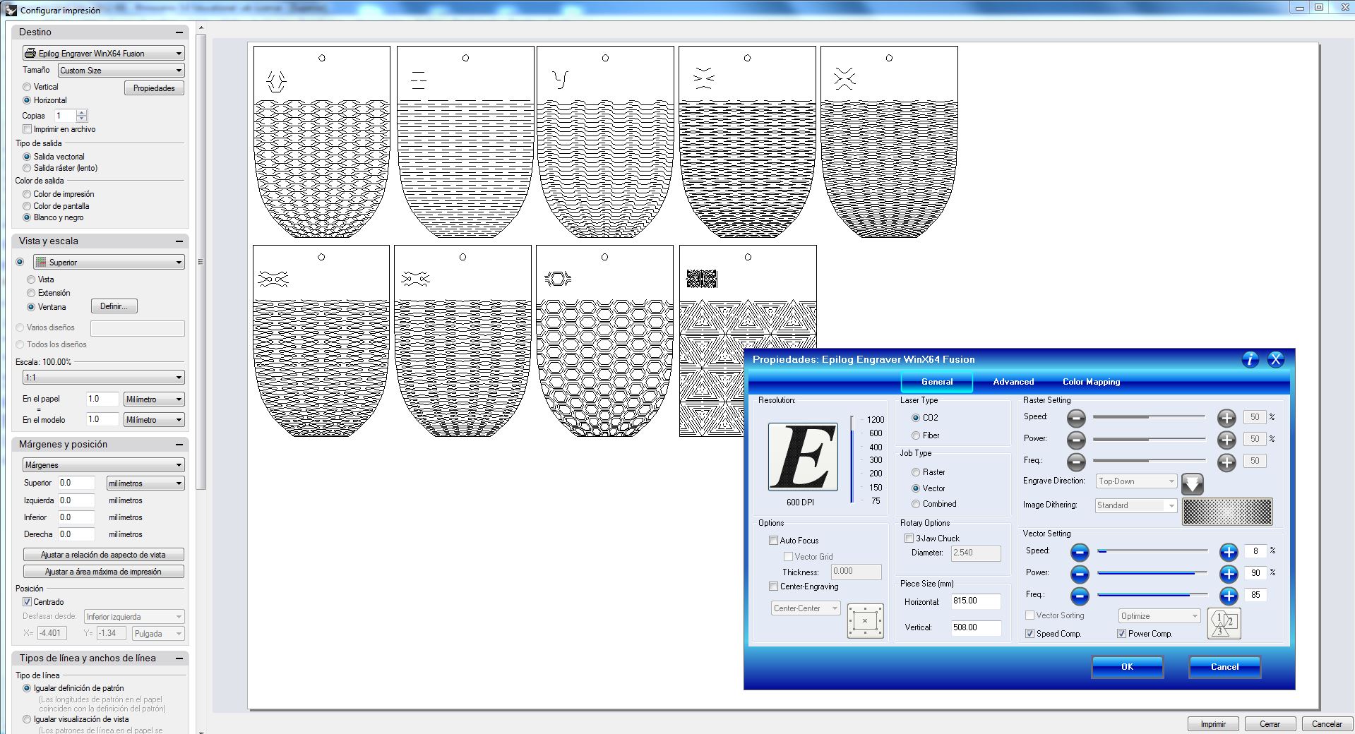
I began with the parametric kerf. One from the templates. The other one from the Living Hinge in Inkscape. I prepare them in a very small scale (75 mm high, see image below with the two options) and I realized that they were SO SMALL to be able to make real experiment results.
After the Regional Review, Nuria Robles advise me that:
_I have to have in my mind our Laser-cut Machine, Epilog, kerf. I have it in my mind and it is 0.1-0.15 mm.
_It is good to experiment with another materials too: take plywood and make living hinge cuts in the direction of the woodgrain and on the contrary.
_Think well how all my parts are going to work to define the angle and the radius they need to apply this kind of cuts.
DOWNLOADS
_ Parametric Kerf sampler files.
_ Living Hinge Swatches files.