Exercise 11. Input Devices
After the lesson about Input Devices, on Wednesday 4th April, the assignment for this week was to:
		INDIVIDUAL ASSIGNMENT:
			_ measure something: add a sensor to a microcontroller board that you have designed and read it

		GROUP ASSIGNMENT:
			_ measure the analog levels and digital signals in an input device
PREVIOUS CONSIDERATIONS
_ Sensors I have selected to this assignment are directly connected to my FINAL PROJECT: Temperature and Humidity sensors.
		I am going to use Tª and %HUMIDITY sensors which are going to be OUTSIDE PCB.
		They will be mounted INTO each plant soil, far away from the PCB:
				_ Soil Temperature is very important when we germinate seeds.
				_ Humidity sensor will allow user to know when each plant needs to be watered.
_ I am going to use, first, PCB I have done in week 07 assignment to test sensors I am going to use, one by one.
_ Then, I am going to design and make a new PCB, but not only thinking in this week assignment, I would like to add output devices connections too for the next week exercise. The idea is to make a "neutral" PCB for different connections (IN and OUT).
INDIVIDUAL ASSIGNMENT
1_First step I wanted to do was to undestand and test each sensor.
For this, I have taken exercise 07 PCB and I have connected each sensor to it, programing it with Arduino lenguage.
2_Then, when I understood them, I continued designing, making and testing a new PCB.
1_TESTING EACH SENSOR
HUMIDITY SENSOR AND ITS PROGRAM
The humidity sensor I am using is which we can see in the image below. It is DFRobot Moisture Sensor .
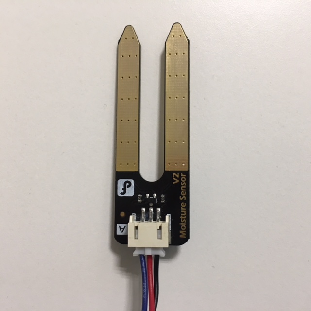
This Gravity: Analog Soil Moisture Sensor For Arduino can read the amount of moisture present in the soil surrounding it. It's a low tech sensor, but ideal for monitoring an urban garden, or your pet plant's water level.
SPECIFICATION:
		Power supply: 3.3v or 5v
		Output voltage signal: 0~4.2v
		Current: 35mA
		Pin definition:
			Analog output(Blue wire)
			GND(Black wire)
			Power(Red wire)
		Size: 60x20x5mm
		Value range:
			0 ~300 : dry soil
			300~700 : humid soil
			700~950 : in water
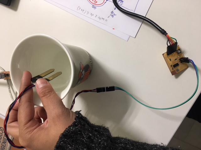
But, I want to be sure these value ranges are working as it says, and I made this first test to see real values it measures out and in water (water must be 100% of humidity by logic).
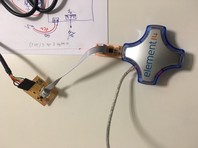
So, I made the program to it and I programmed PCB using USBTinyISP we have done in exercise 05: Electronics Production:
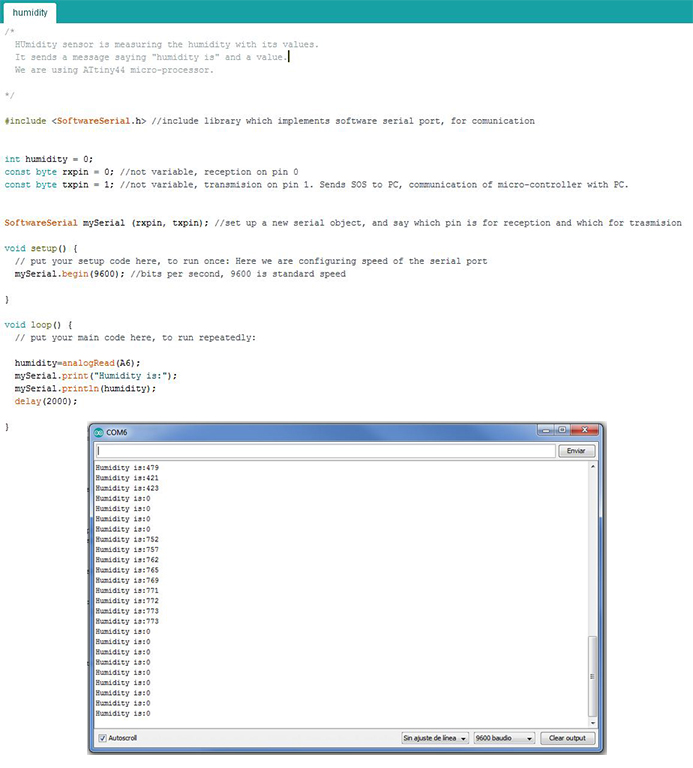
We can see now that it takes a value range between 0 (out of water) and 773 (into the water).
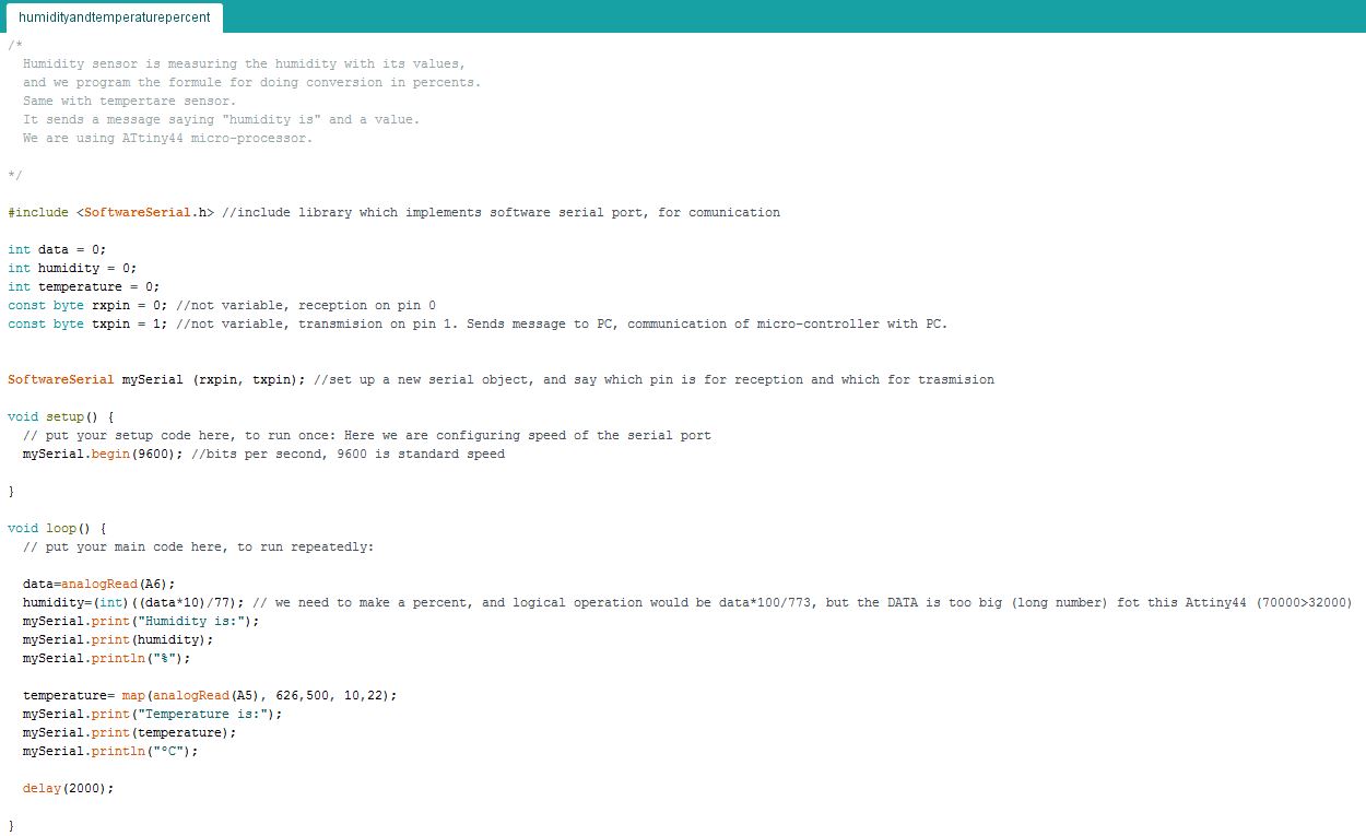
Taking this range in account, I reprogram PCB with a formula to convert values in percents:
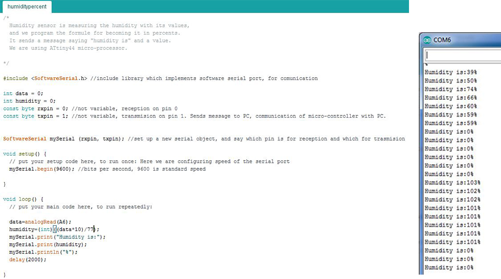
As Tiny44 has a maximun reading value near 32000, and making formula with sensors maximun value it has more than 77000, I had to change formula making it ((valuex10)/77) instead of ((value*100)/773).
Now, it works and I have its program ready.
TEMPERATURE SENSOR AND ITS PROGRAM
I made same procedure with thermistor, the Temperature sensor. I have a NTC thermistor you can see in the image below:
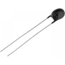
NTC stands for “Negative Temperature Coefficient”. NTC thermistors are resistors with a negative temperature coefficient, which means that the resistance decreases with increasing temperature. NTC sensors are typically used in a range from −55°C to 200°C. I need to see its real "resistor" values, and make a conversion, as before, but this time with a MAP tag.
More info about this type of resistors here.
First of all I made an easy connection with a resistor, it needs one, to, after programming PCB, connect all and see values range I can take from it. You can see it in the image below:
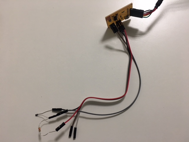
To insert real values, I used FabLabs inside and outside temperatures. I know it this right moment the Tª outside is 10ºC and inside 22ºC. So I first measure Thermistor real value readings outside (650) and inside (500) with the following program:
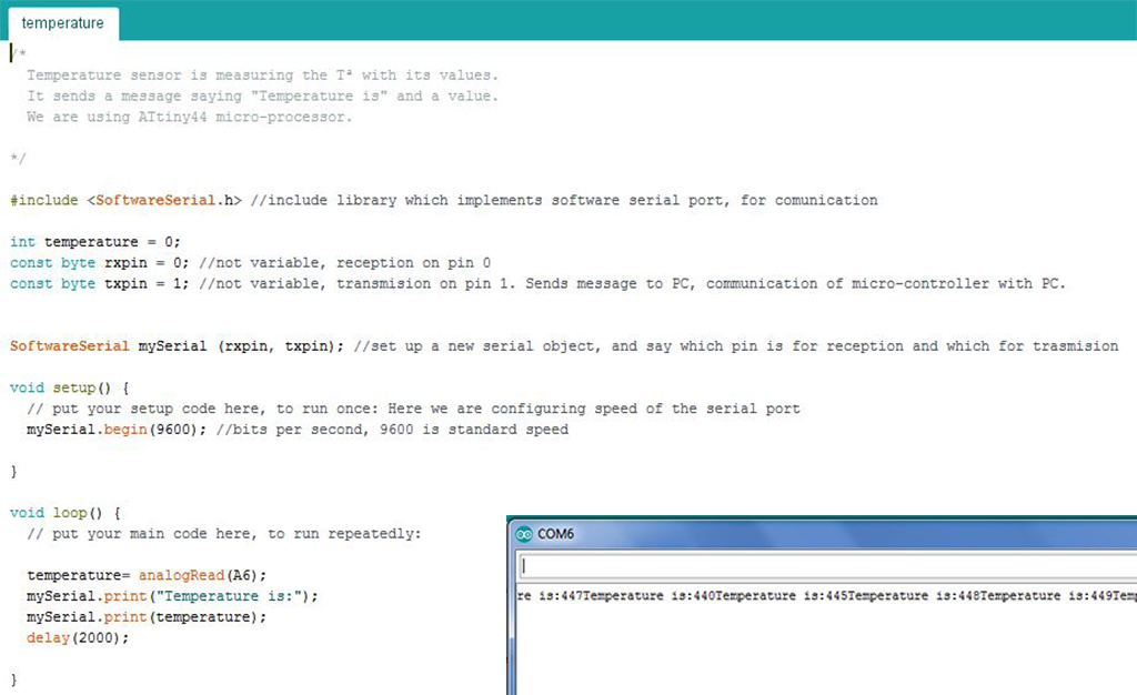
And then I modify code to obtain data in ºC:
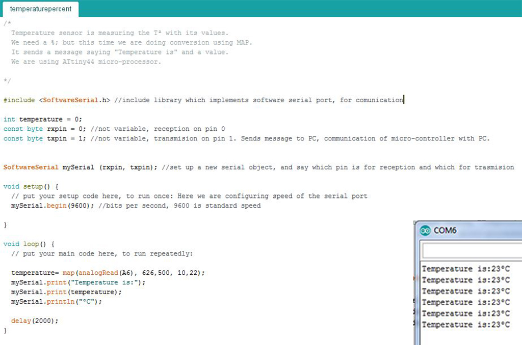
It is working and I have its program ready too. So next step is to design and make a new PCB to connect two sensors together.
2_ HUMIDITY AND TEMPERATURE TOGHETHER. NEW PCB.
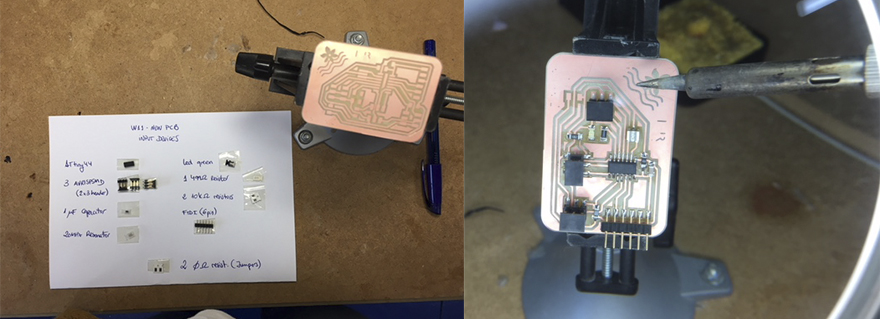
Once I knew how I was going to work, I began to design a new PCB. For this assignment I decided to continue with Tiny44 to simplify it, and I made a list with components I would need:
		- ATTiny44-SSU, micro-controller.
		- 2 AVRISPSMD, 2x3 header: (1) for Tiny44 and another (1) for Input Devices.
		- CAP UNPOLARIZEDFAB, 1uf capacitor.
		- RESONATOR, 20MHz crystal.
		- RES-US1206FAB, resistors: (2) 10k ohm for Tiny44 and Thermistor.
		- FTDI-SMD-HEADER, 6-pin header.
But I know next week I will have to make something with OUTPUT DEVICES: So, I decided to prepare the new PCB for this too. After discussing with my instructor, I decided I will use a Led related to Temperature, and a Servo related to Humidity, and I add this components also to the new PCB:
		(Preparing for Week 12 assignment: OUTPUT DEVICES)
		++
			- LEDFAB1206, one green.
			- RES-US1206FAB, resistor: (1) 499 ohm for the Led.
			- AVRISPSMD, 2x3 header: another (1) for Output Devices.
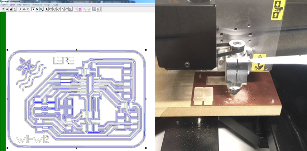
I opened Eagle and, with exercise 07 procedure, I made new PCB Schematic design:
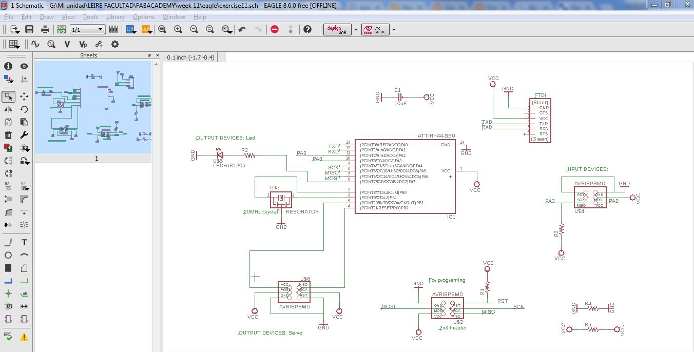
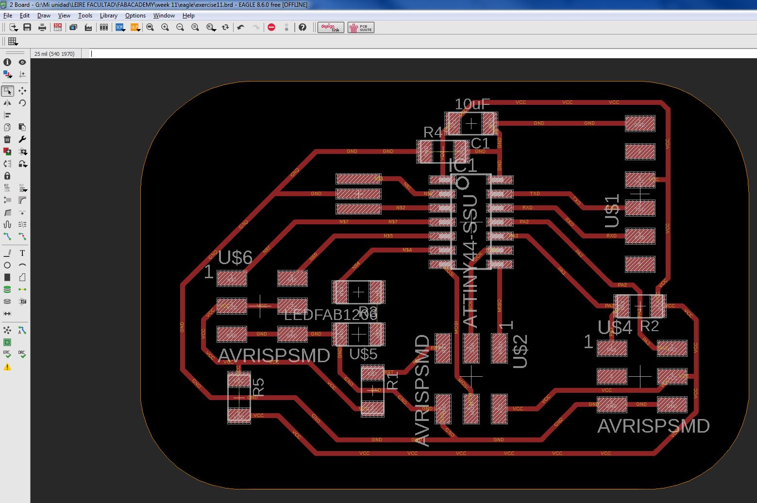
For the board design I had to add 2 0 ohm resistors as jumpers to unite everything well, and this is the result:
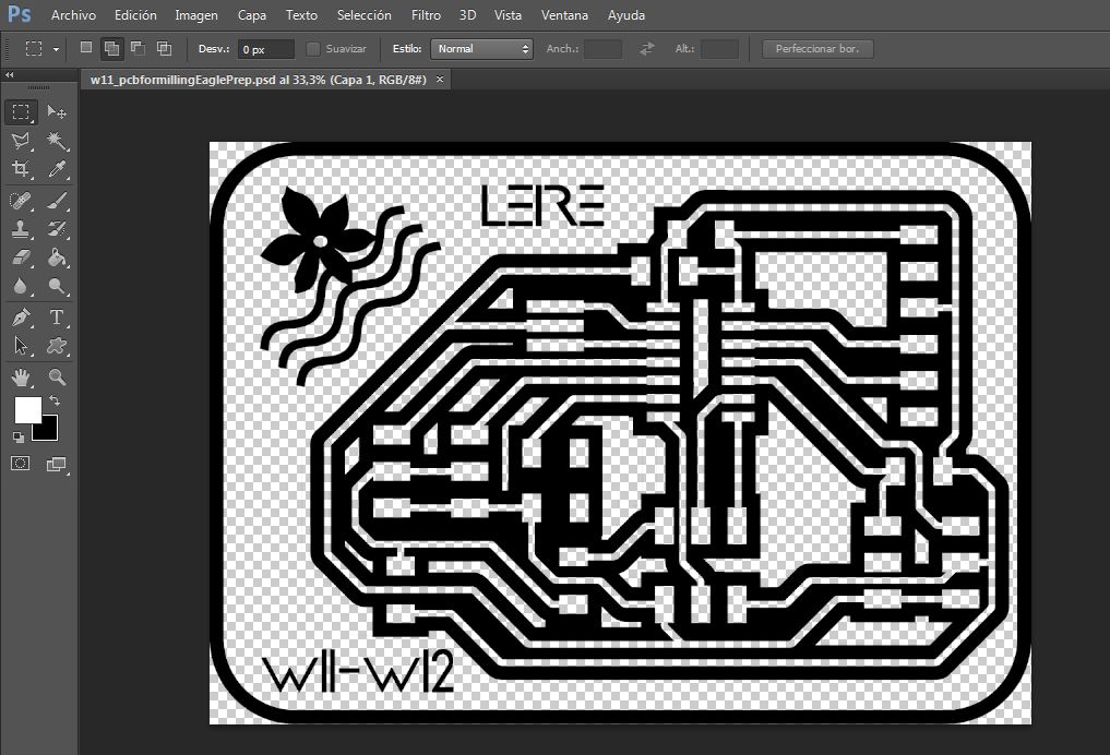
I opened it in Dr.Engrave software to send it to Roland MX40 we have. Tools used are: Engraver V tool and 1mm diameter end-mill (to final board cut).
And finaly, I prepared code, from tests made first, and I made an attempt to program it:
But OUCH! There was a problem with programming it. So, I had to test everything since PCB design, and I found 2 errors:
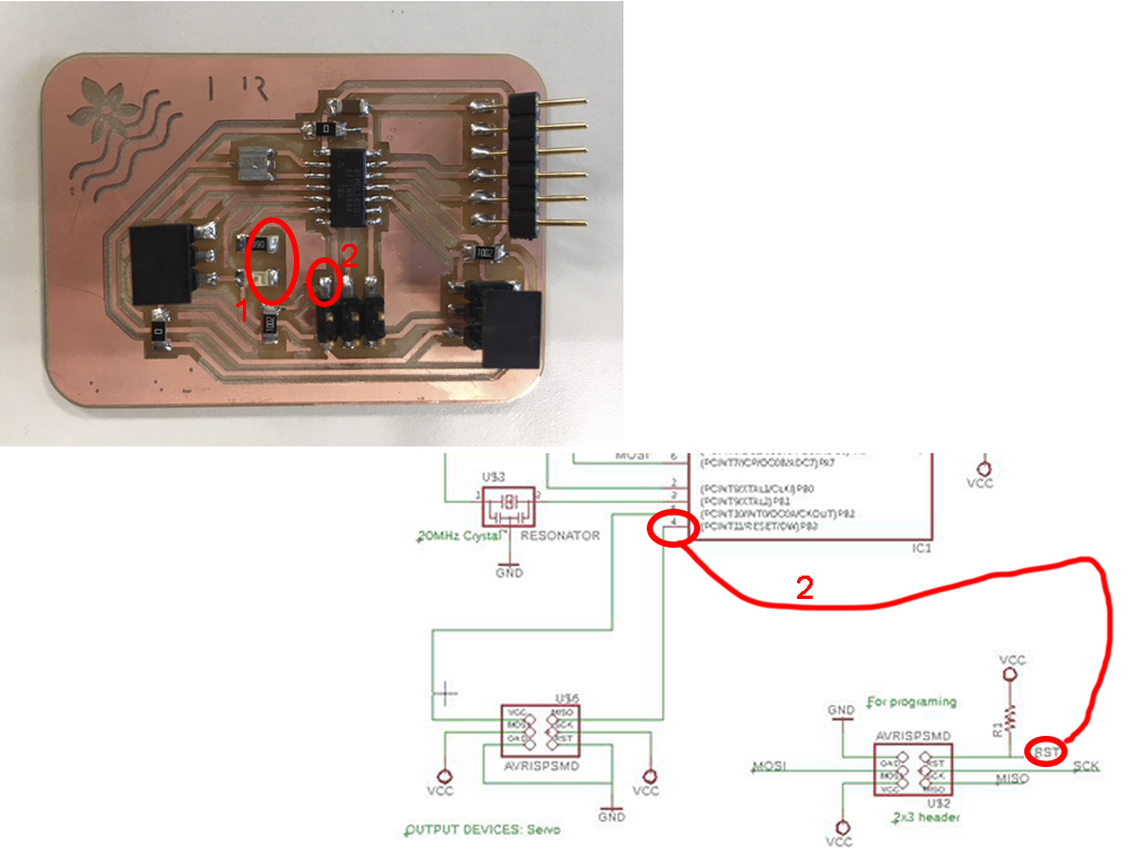
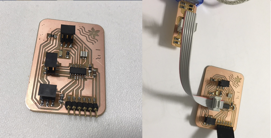
		1_ Led and its Resistor connection is not done:
						- It has ocurred due to Eagle board view, letters were hiding it and I did not noticed it.
						- As it is a component to week 12 assignment, I will fix it next week.
		2_ I used RST pin which is to program PCB for an Output Device, and it can not be:
						- I do not want t do a Fuse to disable RST pin and use it as PB3 always
						- NOW, only for this assignment, I will connect it with a cabe, as you can see in the image below:
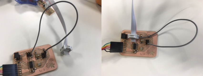
Programming is working now, so, I connect sensors to the PCB:
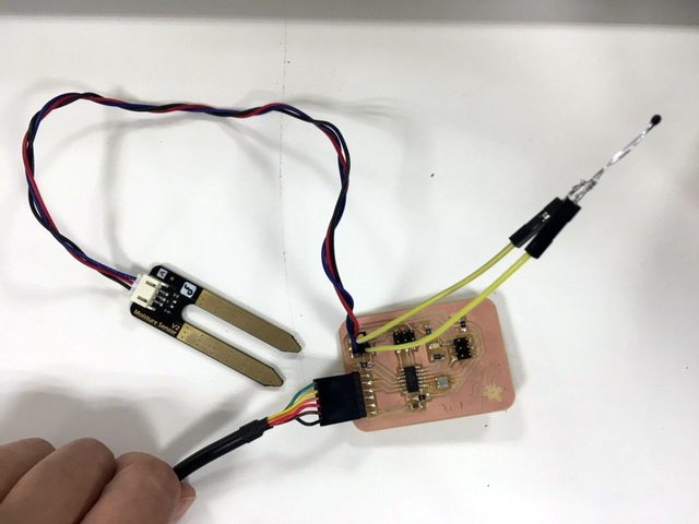
And I test it in water and into my little lettuce pot:
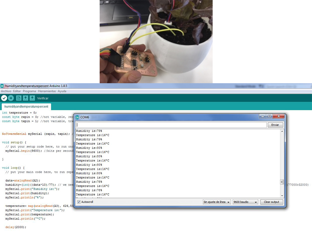
IT IS WORKING AND SENDING ME DATA! OUH YEAH!
*I have updated the PCB fixing the errors I have found here in exercise 12. Output Devices.
GROUP ASSIGNMENT
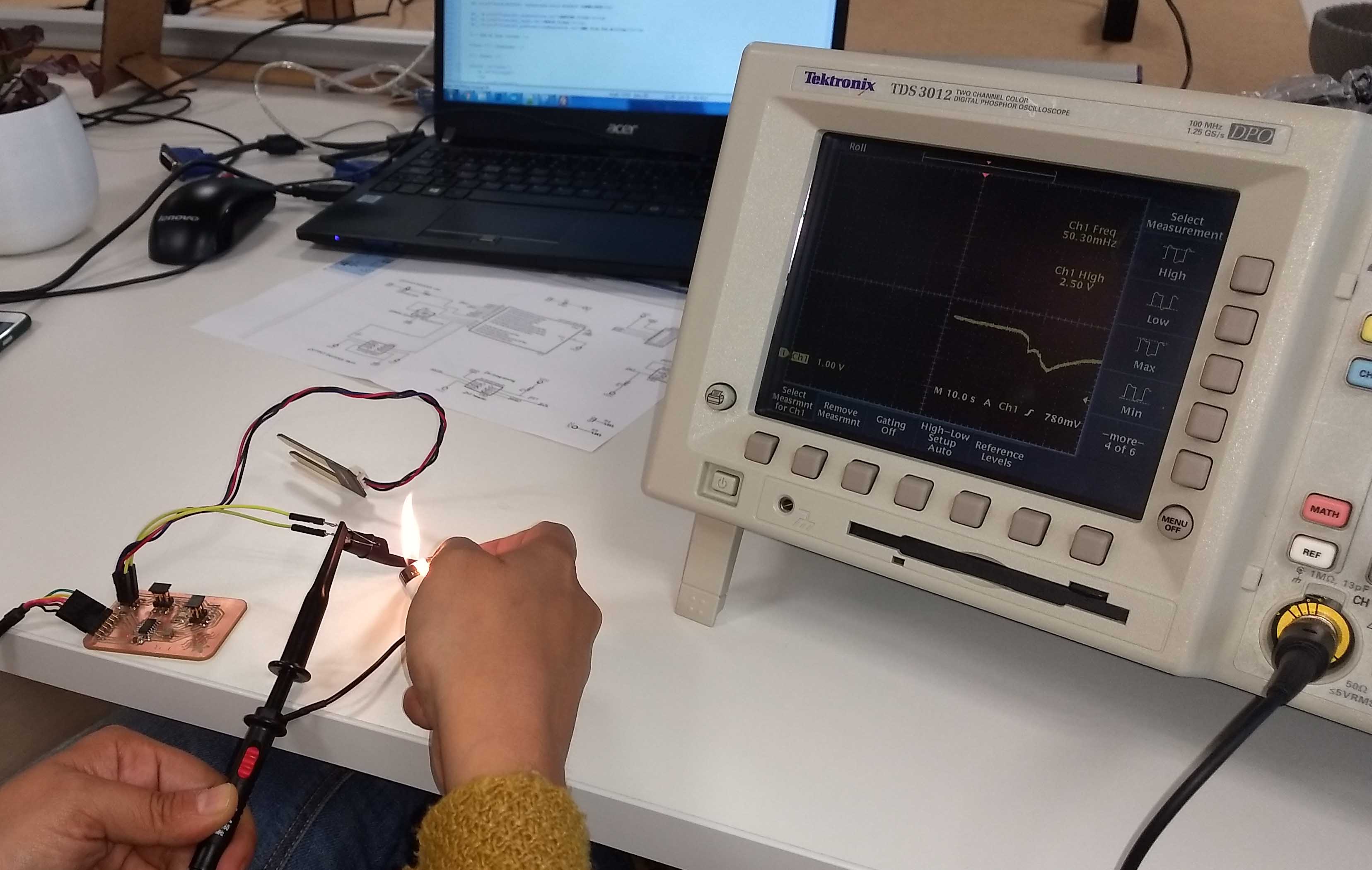
For measurement of an analog level we have used Leire's new PCB, and specifically NTC Thermistor levels. We have take a Oscilloscope and connect the probe to its two cabes. It has to, logically, drop down its signal level when we warm it.
We have warm it with a lighter, and then we have been waiting to see how it is going back to initial level. You can apreciate it in the image below:
And for viewing of the digital signal, we have used exercise 07 PCB , which has a button, and using a Multimeter (Tester, Polimeter, Voltimeter) we have seen how the measurement of the voltage changes. When we push the button, we close the circuit and VCC goes into it.
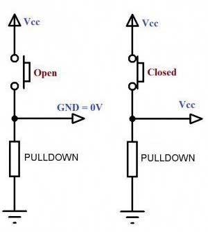
We can read it in Multimeters screen as you can see in the next video: