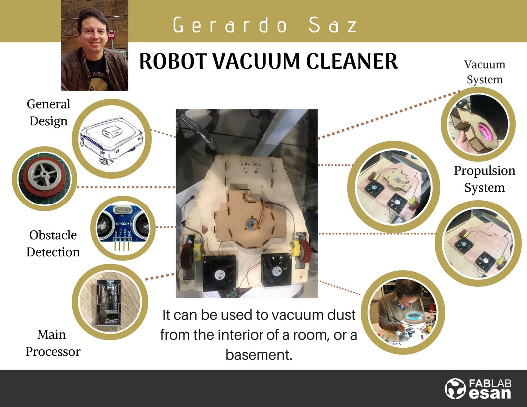
My Final Project
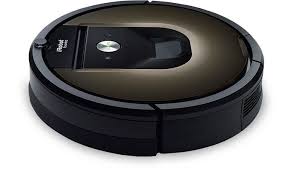
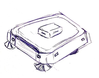
My final project is a robot vacuum cleaner based on iRobot's Roomba, although with my own design.
I chose this project because I will apply the knowledge I have
learned in the assigments below to build the robot vacuum cleaner
- Project manager, to plan and document the progress of the project
- Computer-aided design, to investigate on the right software for the product design
- Computer-controller cutting, for investigate and learn about how to cut flat pieces for my project
- Electronics production, will help me to make the PCB using the milling
- 3D scanning and printing, for the printing the internal supports and prototypes of parts and pieces of the vacuum cleaner
- Electronics design, will help me to investigate about electronic circuit design software and prepare my own plates
- Embedded programing, will help me to investigate programming languages for microcontrollers in my project
- Output devices, for work on the engines of the vacuum cleaner
- 3D molding and casting, for the manufacturing pieces, for example the wheels.
- Input devices, for work on the sensors of the vacuum cleaner
- Networking and communications, in order to specify the wireless communication between the cell phone (through which the command will be issued) and the vacuum cleaner.
- Interface and application programming, regarding the tools to program the communication interfaces
- Applications and implications, to formulate my final project using everything learned and researched
- Invention, intellectual property, and business models, to prepare documentation of licenses.
Once it is finished it can be used to vacuum dust from the interior of a room, or a basement.
Even though we can find this kind of vacuum cleaner in the national market, I believe that designing and building a
vacuum cleaner under the scheme proposed by Fab Academy will allow me to give an option for this product at a lower price.
In fact, in Lima, Roomba vacuum cleaner can cost more than 50% of the price that it is in the United States.
In fact, in Lima, Roomba vacuum cleaner can cost more than 50% of the price that it is in the United States.
The robot will have the following functionalities:
- Operable from a mobile application or automatically,
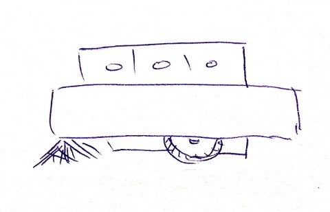
- Wheels for displacement that allow 360 ° rotation,
- Rechargeable battery,
- Sensors to avoid obstacles or falls,
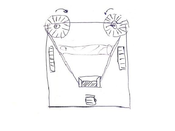
- Side brushes for sweeping dust,
- Aspiration system,
- Trash container with filter,
- Design with smooth and rounded surfaces, and
- Positional lights to avoid accidental tropping
Schedule
| Job \ Weeks | 1 | 2 | 3 | 4 | 5 | 6 | 7 | 8 | 9 | 10 | 11 | 12 | 13 | 14 | 15 | 16 | 17 | 18 | 19 |
|---|---|---|---|---|---|---|---|---|---|---|---|---|---|---|---|---|---|---|---|
| 1.0 GENERAL DESIGN | |||||||||||||||||||
| 1.1 Project proposal | |||||||||||||||||||
| 1.2 Distribution of components | |||||||||||||||||||
| 1.3 Exterior design | |||||||||||||||||||
| 1.4 Interior design | |||||||||||||||||||
| 2.0 VACUUM SYSTEM | |||||||||||||||||||
| 2.1 Get a motor brushless | |||||||||||||||||||
| 2.2 Vacuum propeller | |||||||||||||||||||
| 2.2 Vacuum box | |||||||||||||||||||
| 2.3 Fan controller | |||||||||||||||||||
| 2.4 Rollers | |||||||||||||||||||
| 2.5 Brushes | |||||||||||||||||||
| 2.6 Motor and transmission | |||||||||||||||||||
| 2.7 Side skirts | |||||||||||||||||||
| 3.0 POWER SUPPLY | |||||||||||||||||||
| 3.1 Get batteries | |||||||||||||||||||
| 3.2 Recharging circuit | |||||||||||||||||||
| 4.0 PROPULSION SYSTEM | |||||||||||||||||||
| 4.1 H-Bridge Motor Controller | |||||||||||||||||||
| 5.0 NETWORKING | |||||||||||||||||||
| 5.1 Bluetood controller | |||||||||||||||||||
| 6.0 OBSTACLE DETECTION | |||||||||||||||||||
| 6.1 Input devices | |||||||||||||||||||
| 7.0 ILLUMINATION | |||||||||||||||||||
| 7.1 Lights controller | |||||||||||||||||||
| 8.0 MAIN PROCESSOR | |||||||||||||||||||
| 8.1 Fabduino |
Bill of Materials
-
Electronics:
- 1 6-pin connectors
- 2 A4953
- 3 attiny44
- 3 AVRISP 2x3
- 2 cap 0.1uF
- 2 cap 10uF
- 3 cap 1uF
- 3 HC-SR04
- 1 header male 1x6
- 2 header male 2x2
- 1 header male 2x5
- 1 mini-usb connector
- 3 MOTOR GEAR
- 3 PCB 2x3in
- 6 Res 0k
- 2 Res 100 ohm
- 3 Res 10K
- 1 Res 1k
- 1 Res 499 ohm
- 2 Resonator 20MHz
- 1 ribbon cable
- 1 USB connector
- 1 usb mini cable
- 2 Zener Diode 3.3V
-
3D Printing:
- 1 PLA
- 1 PVA
-
Laser Cutting:
- 1 MDF plate 600x300mm
-
Moulding and Casting:
- 1 Silicone type F-20 Plus
- 1 CP-40 Plus catalyst
- 1 Mold Max 60 Silicone rubber compound and its catalyst
- 1 Block blue wax
Construction of the final project
- Vaccum System
- Propulsion System
- Proximity sensors
- Sweeping brooms system
- Chassis and case of the vacuum cleaner
Vacuum System
With what I learned in "Computer-controlled cutting", parametric design with Grasshopper and in "3D scanning and printing", I designed the aspiration system.Suction propeller
For the design, I helped myself with some images from the internet. The turn of the propeller had to create a vacuum that attracted dust particles. I chose the third type of propeller.

I used parametric Grasshopper design to make the propeller

In this image, FlashForge Creator Pro 3d printer is printing the base of the suction propeller.

In this image, the printing is over, some filaments are seen inside, they are the supports.

Here you can see in more detail the supports and how the base is detached.

In this image, you can see the bottom part of the base on which the propeller was printed.

This is a top view of the propeller, before removing the supports, you can also see the filling in the form of hexagons.

Files to Download
Brushless motor controller
To make the driver of the brushless motor,
I used the assignment "output devices", unfortunately the motor did not work,
I will leave for a second stage to investigate more about the A4941 microcontroller.
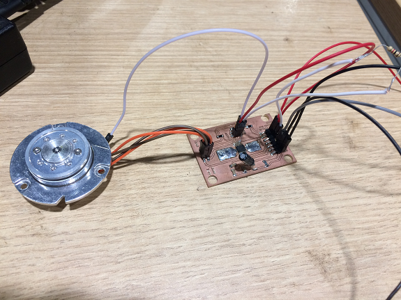
For that reason I made another circuit to control the engine,
based on what I found on the internet Link .
I made this schematic diagram with Livewire.
I made this schematic diagram with Livewire.

Funcionality test
This is just a test run of the suction propeller with 9 volts from some batteries and with an Arduino to test the program.
I will not use Arduino in the project.
This is just a test run of the suction propeller with 9 volts from some batteries and with an Arduino to test the program.
I will not use Arduino in the project.
Files to download
Suction box
For the design of the suction box I was inspired by the coolers that are inside the Mac. The box has a circular shape but the axis of the propeller is eccentric to the axis of the box.

Propulsion System
Gear motor controller
The PCB controller of the robot engines I did with what I learned in "Output Devices", the detail of the design and manufacturing are there.
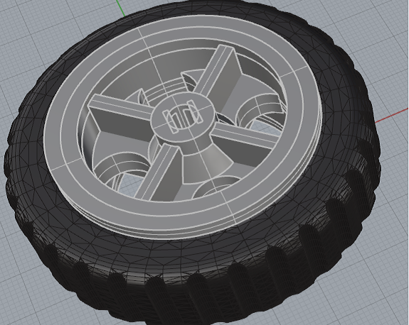
Wheels and Tires
With what I learned in "3D scanning and Printing" I made the rims of the robot vacuum cleaner's wheels.Here some images. More details, click here.
In the "Molding and Casting" assignment, design the robot tires.

Proximity sensors
Ultrasonic sensors 3in1
For the design and manufacture of the sensors I used everything learned in "Input Devices".
So that the robot can move without hitting any object, in my design the robot has three ultrasound sensors, controlled with a PCB.
These are the schematic and PCB diagrams. I added texts to indicate the location of the cables that go to the sensors.


After finishing the PCB milling, I proceeded to weld the components.

In this image you can see the three sensors connected to the controller card with an ATTiny44.
Files to download

Here, we see a zoom to the PCB with the connections.

Sweeping brooms system
The swept system consists of a gear motor, two transmission shafts, four straight bevel gears and brooms.Transmision Shafts
I designed the transmission axis parametrically, using Grasshopper from Rhinoceros. As it is going to be subjected to torsion, I put a diameter of 14mm.

Once I finished the design, I exported it as an STL file. and I edited it in BNC3D Cura, there I reinforced the filling density. At one end, it has a hole to be assembled on the shafts of the gear motor, and on the other, it will assemble with a bevel gear, to prevent the shaft from resurfacing with the movement, I leaked a key that fits inside the gear.

The best way to print the transmission axes is horizontal. In this way, with the effort they do not break. The printing took 2 hours 13 min.

This is the transmission axis, without the supports or the base. You can see the detail of the key on one end.
Files to Download
Files to Download

Conic Gear
To change the direction of movement of the motor to the brooms I manufactured four straight bevel gears.
The design can be seen in "Computer-aided Design" and for
printing it was useful "Scanning and printing"
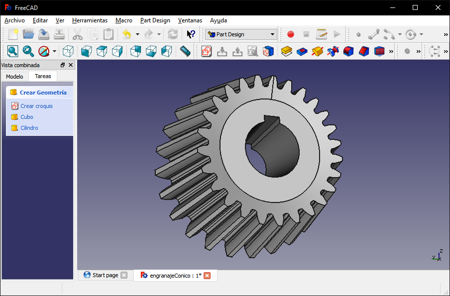
Video of the 3d printing of one of the bevel gears.

Brooms
The swept system consists of a gear motor, two transmission shafts, four straight bevel gears and brooms.
The brooms were made with parametric design using Grassshopper. The cylindrical shape fits into the hole of the bevel gear, the rod is to be able to easily remove the broom from the gear when it requires change.

In this image you can see a simulated cut of the inside of the brooms, to reinforce them and avoid breakages I changed the height of the layers to 0.14mm, the width of the walls to 1.6mm (red and green) and the filling to 75% with a octagonal pattern (yellow color).

Difficulties during 3d printing
The printing of the three brooms (one is spare) would take 1h50min, but at 27 min the filament was broken. Fortunately, I was nearby and I got the impression.
I checked the filament and found several brittle stretches. The filament becomes brittle if it is exposed to humidity, in Lima - Peru humidity is 70% or more, so special care must be taken with its storage.
The break usually occurs at the pressure point of the printer's traction gear. As soon as the filament breaks, the extrusion stops, because nothing drives it.

I changed the filament for another one. I checked this filament doing a simple test, with the fingers double a piece of filament, if it breaks at 90 ° I keep trying, until I find a stretch that only be bent.
Despite that, this time I sent to print one by one.
The best way to print a piece subjected to pressure is with the horizontal axis, because if they are printed vertical, it is very likely that they split by the union of a layer when being subjected to pressure.
Despite that, this time I sent to print one by one.
The best way to print a piece subjected to pressure is with the horizontal axis, because if they are printed vertical, it is very likely that they split by the union of a layer when being subjected to pressure.

These pieces are brooms, they will be assembled by the bottom of the robot. Still need to stick a few brushes in the holes.
3d printing took 30 minutes.
3d printing took 30 minutes.

For the bristles of the brooms I used the bristles of a 3" wide brush.

Cut them, grouped them and glued them with a bit of glue in the holes of the piece.


In this picture it is already in place with the brushes attached.
Files to download
Files to download

Chassis and case of the vacuum cleaner
Chassis
The chassis is the structure that supports all the components of the vacuum cleaner, I designed one high enough to move on a carpet or a small unevenness of the floor, but not so high that you lose the suction power of the engine. The material that I used to make the chassis was a 3mm MDF plate. I made the design in Rhinoceros with Grasshopper, totally parametric.
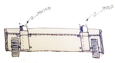
I attached the wheel motors on the inner side of the base of the chassis, so that the wheels can be seen through side holes.
In the central part I made the suction hole.
On the left and right front I made the holes for the motor supports and broom gear system.
In the central part I made the suction hole.
On the left and right front I made the holes for the motor supports and broom gear system.
I imported the other pieces that I had already designed and with them I could define the final dimensions.


I designed a 28mm x 28mm plate with Grasshopper with rounded corners to avoid clogging.

I re-located the motors and wheels at the ends and with the "solid intersection" component I made the holes for the wheels.


Case
To cover and protect mobile and electronic parts, I designed a case with Grasshopper.

With the "rectangle" component, I created a rectangular figure around the base and with the "extrusion" component raised the figure 53mm, just enough to cover all the elements of the robot.

Then, with the "Fillet Edge" component round the upper edges.

For access to the garbage container, I used the "Rectangle" component with the same dimensions as the lid of the container but with the height of the case.
Then, with the "Intersection of solids" component, I obtained a solid with the same curvature as the rest of the case.
Then, with the "Intersection of solids" component, I obtained a solid with the same curvature as the rest of the case.


And to have clear the area of the sensors I added some rectangles of the same dimensions of the sensors.
I selected the resulting pieces and with the "Bake" command I created the Case models. Then this model I exported as STL.
I selected the resulting pieces and with the "Bake" command I created the Case models. Then this model I exported as STL.

Files to download
To build the base of the mold I used "Slicer for Fusion 360", this software is very intuitive, with it you can quickly get cuts in 2d of a 3d object.
In the following image shows the STL file just imported to Slicer.
In the following image shows the STL file just imported to Slicer.

Before continuing, it is highly recommended to define the size and thickness of the material that will be used. In my case, I used a 500mm x 700mm sheet of 3mm corrugated cardboard. these measures must be defined in "Manufacturin Settings".
On the right side of the cutting simulation you can see the distribution of pieces 2d on the previously defined sheet.
On the right side of the cutting simulation you can see the distribution of pieces 2d on the previously defined sheet.

You can add, move or eliminate slices.
To export the cutting plans, you must go to the "Get Plans" menu and select export as a DXF file.
To export the cutting plans, you must go to the "Get Plans" menu and select export as a DXF file.

This is the view of all the pieces that make up the mold for the case.

For the cutting of the pieces I used everything learned in "Computer-controlled cutting"
In the second image I already had the pieces ordered for the assembly.
In the second image I already had the pieces ordered for the assembly.


All the pieces have a numbering in the central part and next to each assembly slot the numbering of the piece in which it must fit.


As soon as I finished assembling all the parts I began to cover it with tape and paper to give it a profile as rounded as possible.


First assembly
Here we can see the pieces together, still re-wiring, the operational tests and the cover.
Here we can see the pieces together, still re-wiring, the operational tests and the cover.

Funcionality test
This is just a test of brooms with 5 volts from an Arduino board. At that time I did not have the source finished.
I will not use Arduino in the project.
This is just a test of brooms with 5 volts from an Arduino board. At that time I did not have the source finished.
I will not use Arduino in the project.
This is part of my presentation of my final project to Esan students
Operation test
In this test, the vacuum works autonomously, and collects dust, pieces of paper and hair from the floor.
This project is licensed under a CC-By-NC-ND (Attribution-Non Commercial-Non derivate) Creative Commons license
