Week 9
Molding and Casting
The theme of this week was "Molding and Casting", with this I learned to design appropriate objects within the limitations of 3-axis machining and to demonstrate the workflows used in the design of the molds, construction and casting.
The objective of this assignment was:
The first thing I did was to see how this assignment could help me with my final project.
- Design a 3D mold with the material and tools that I have used, machine it in the CNC milling machine and use it to cast parts.
I had several ideas: the dust and garbage container in acrylic resin, the silicone tires, the sweeping rollers. I chose to make the tires.
Original design
My Workplan
My workplan was as follows:
1. Design a wheel and tire.
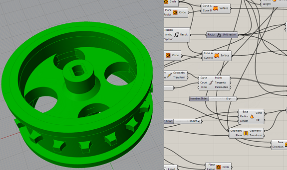
For the design of the wheel and the tire I used Grasshopper by Rhinoceros, this parametric design tool
allowed me to move forward with the design and make adjustments and tests just by changing the parameters.
To design the tire, I needed to design the complete wheel.
The wheel rim should fit with the tire and should not move.
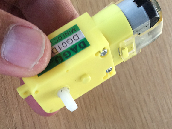
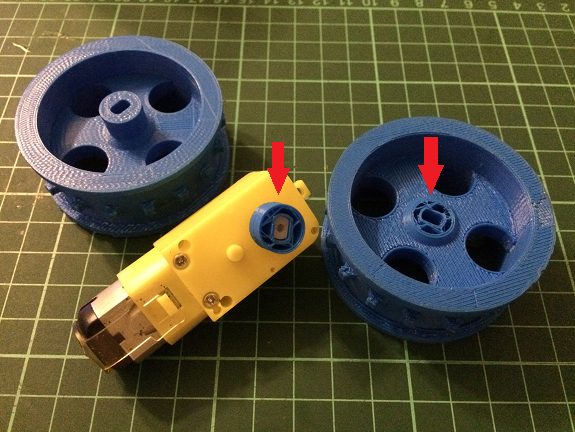
Each wheel will be driven by a gear motor. The motor shaft has a diameter of 5.6 mm, then the diameter of the hole must have a tolerance that allows a press-fit with the motor shaft.
Each wheel will be driven by a gear motor. The motor shaft has a diameter of 5.6 mm, then the diameter of the hole must have a tolerance that allows a press-fit with the motor shaft.
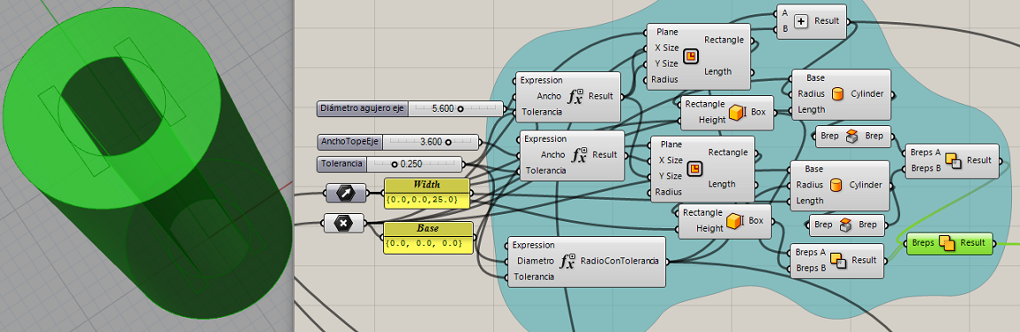
In the following image shows how I made the parametric design of the wheel axis, with a tolerance of 0.25mm.
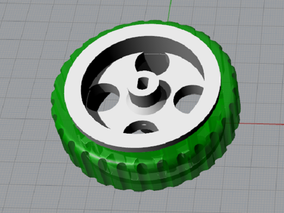
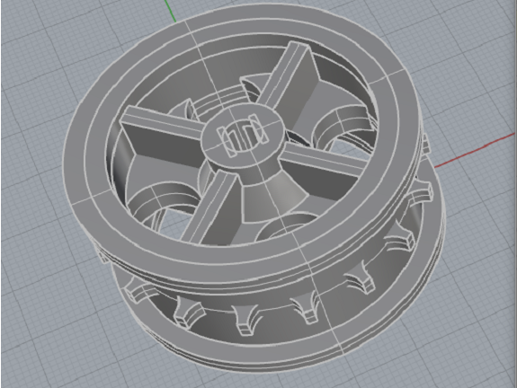
In this picture you can see the design of the rim,
I added some holes to make the spokes and some teeth on
the surface of the rim so that the tire does not move.
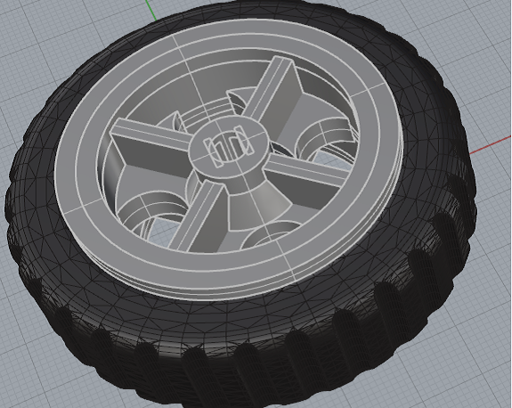
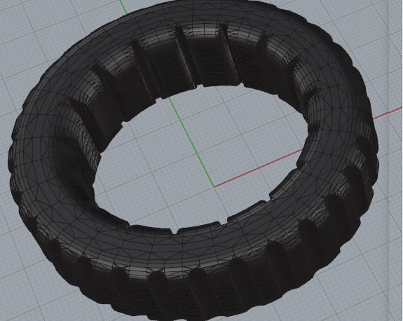
This image shows the design of the tire, with a subtraction of cylinders around the tire I added the tread.
The 3d printing time of the rim was 2h 25min.
I did it on the 3d printer "BCN3D Sigma", with 3mm PLA filament.
I did it on the 3d printer "BCN3D Sigma", with 3mm PLA filament.
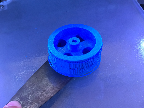
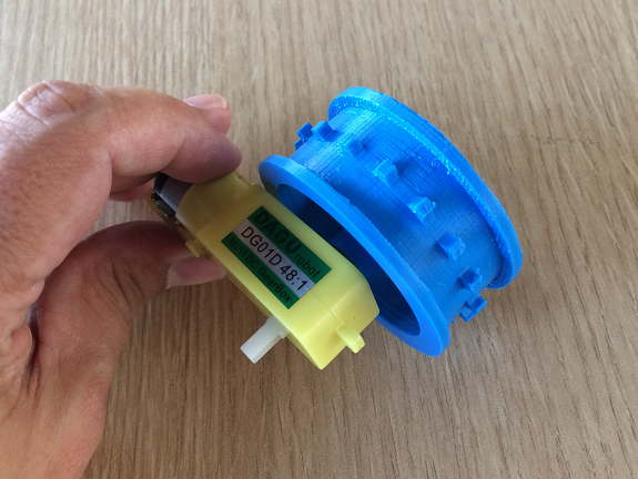
This is a press-fit test with the gear motor.
Design Issue
Although, it seemed that the design was ok, but the truth was that the structure was weak and would not withstand efforts or blows.
Here you can see the pieces broken after falling to the floor.
Although, it seemed that the design was ok, but the truth was that the structure was weak and would not withstand efforts or blows.
Here you can see the pieces broken after falling to the floor.
Solution
I enlarged the cone-shaped reinforcement in the union of the axle with the spokes and added four radial reinforcements, in this way the load will be distributed and will not break.
I enlarged the cone-shaped reinforcement in the union of the axle with the spokes and added four radial reinforcements, in this way the load will be distributed and will not break.
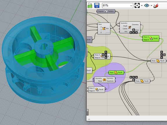
This image shows the new version with the reinforcements, after using the bake command.
Files for download, at the bottom of the page
This image contains the changes in the design of the rim, I have included how it would look with the tire.
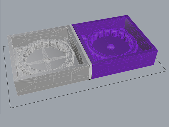
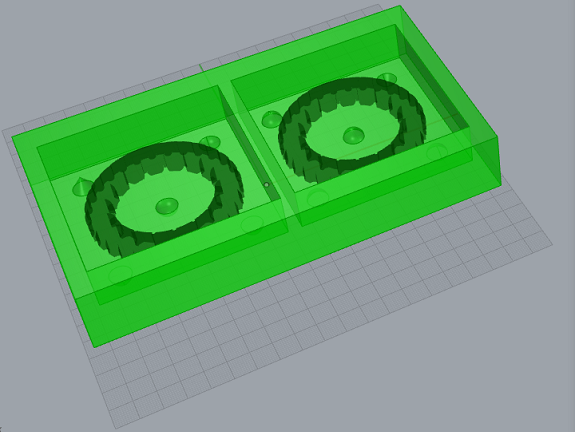
This image shows the tire, to make the mold I split the design in two with the Split component and I put them in a box with the Move and Rotate components.
These two images can be seen both parts of the tire already placed inside the boxes,
to which I put four spheres and a cone so that the molds assemble in the correct position.
With the bake command I obtained the object in Rhinoceros and then I exported it as an STL file (stereolithography).
With the bake command I obtained the object in Rhinoceros and then I exported it as an STL file (stereolithography).
Files for download, at the bottom of the page
2. Milling the mold.
With the STL file, I was ready to start milling the mold.
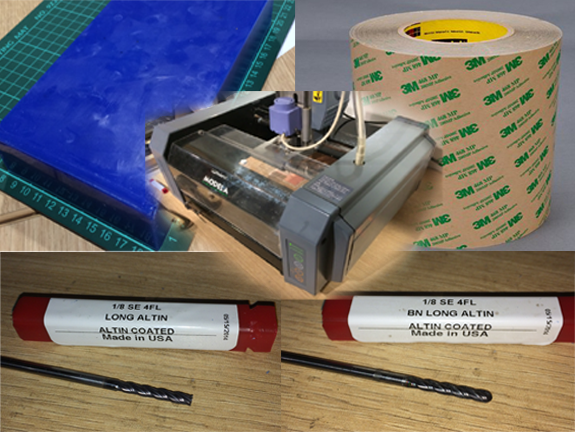
To make the mold I used a block of blue wax of 19.5cm x 13cm x 3cm, this wax is used to make molds for jewelery, dental, etc. It is suitable for making detailed molds, can work with mechanical methods, can cut, file, grind or melt. (107°C)
To make the mold I used a block of blue wax of 19.5cm x 13cm x 3cm, this wax is used to make molds for jewelery, dental, etc. It is suitable for making detailed molds, can work with mechanical methods, can cut, file, grind or melt. (107°C)
Materials and equipment needed
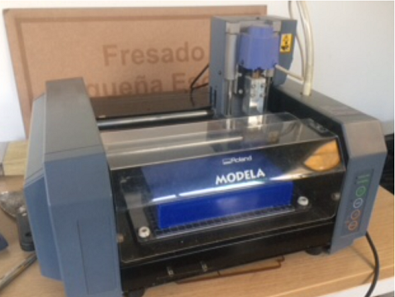
- Roland MDX-20 milling machine.
- Blue wax block 19.5cm x 13cm x 3cm.
- Adhesive transfer tape.
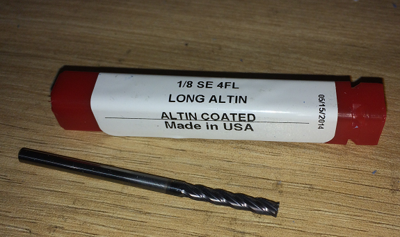
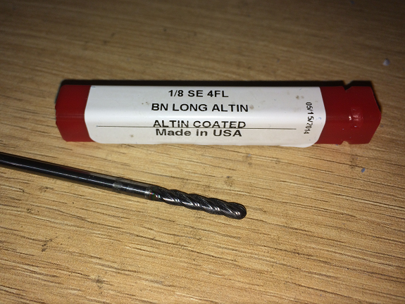
- Milling drill 1/8", flat tip.
- Milling drill 1/8", rounded tip.
The milling process
The work of milling is done in two stages, in the first stage, the milling bit with a flat tip is used, with it the roughing of the material is done until very close to the shape of the model. Then, in the second stage, the round tip milling bit is used, with it you get to shape the model.
The work of milling is done in two stages, in the first stage, the milling bit with a flat tip is used, with it the roughing of the material is done until very close to the shape of the model. Then, in the second stage, the round tip milling bit is used, with it you get to shape the model.
With the STL file and the blue wax block I went to the computer connected to the Roland MDX-20
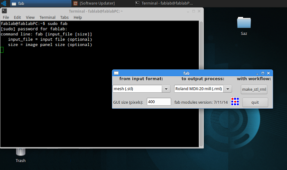
In the terminal of the computer connected to the router I executed the command "sudo fab" and the password,
then I selected the input format: "mesh (.stl)" and the output process: "Roland MDX-20 mill (.rml )",
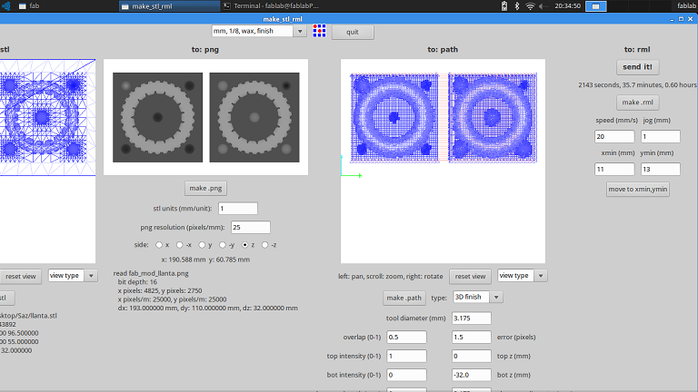
then I pressed the "make_stl_rml" button.
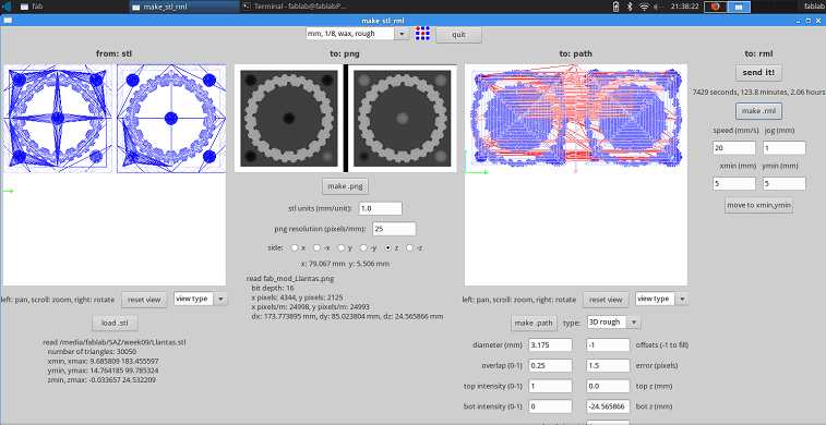
On the "make_stl_rml" screen, I selected the type of milling bit that I will use, in this case the 1/8" flat tip.
Then I loaded the STL file, the geometry of the model is shown on the left side of the screen as an object of triangular polygons. Then I clicked the "make .png" button to create a PNG file at scale scales that represent the depths of the model.
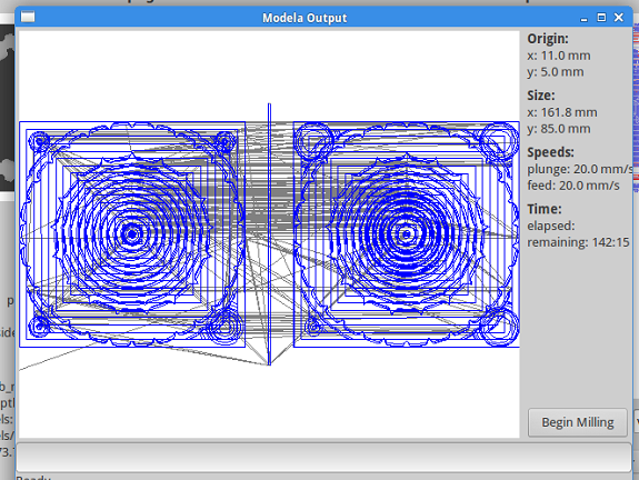
The next step was to create the path, by clicking on the "make .path" button, after a few minutes of processing the paths that the milling bit will follow will be drawn on the right side of the screen.
Then I loaded the STL file, the geometry of the model is shown on the left side of the screen as an object of triangular polygons. Then I clicked the "make .png" button to create a PNG file at scale scales that represent the depths of the model.
The next step was to create the path, by clicking on the "make .path" button, after a few minutes of processing the paths that the milling bit will follow will be drawn on the right side of the screen.
After preparing the first job, I installed the milling bit on the router's mandrel and made the height calibration,
in the same way as the "Electronic production" assignment.
With everything ready, I pressed the "make .mrl" button, process a few seconds and calculated the milling time in 2 hours.
After 2 hours passed, the mold already had some form. But I realized that I had made a mistake when placing the bit in the milling machine.
I should have put the flat-tipped one, and not the round-tipped one.
It was not such a big mistake, I thought, so I continued with the second stage. I turned off the router, and repeated the process of calibrating the height.
In the program I changed the job to "mm 1/8, wax, finish". But when I started the milling job, I noticed that the milling cutter hit one side and did not touch the opposite side. So for fear of breaking the tool, I aborted the job
In the program I changed the job to "mm 1/8, wax, finish". But when I started the milling job, I noticed that the milling cutter hit one side and did not touch the opposite side. So for fear of breaking the tool, I aborted the job
I took the opportunity to review and improve the design of the mold from Grasshopper, I took the measurements of a new block of blue wax and redesigned the box for the mold, I made it as big as possible so that the tire could be a little bigger.
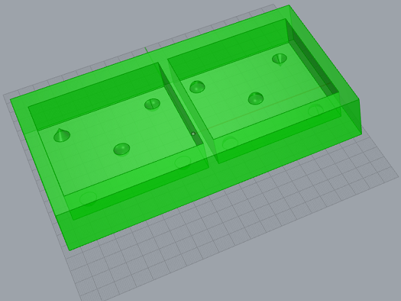
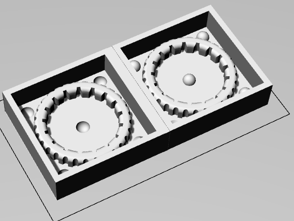
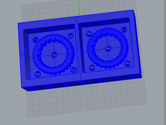
This is the new mold with both sides of the tire, and the object created with the "Bake" command ready to export as an STL file.
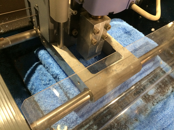
With the new STL file ready, I started the milling job, this time I placed the milling bit 1/8" flat tip.
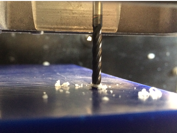
The following image shows the moment when the milling drill touches the surface of the blue wax block.
The following image shows the moment when the milling drill touches the surface of the blue wax block.
This image shows the new milling job, the first stage, with the flat milling drill lasted 2 hours 15 minutes,
While the second stage, with the round tip milling drill took 36 minutes.
Recommendation
The process of milling in the Roland MDX-20, produces a large amount of waste, it would be good if the machine had a system of aspiration of waste like the Shopbot.
The process of milling in the Roland MDX-20, produces a large amount of waste, it would be good if the machine had a system of aspiration of waste like the Shopbot.
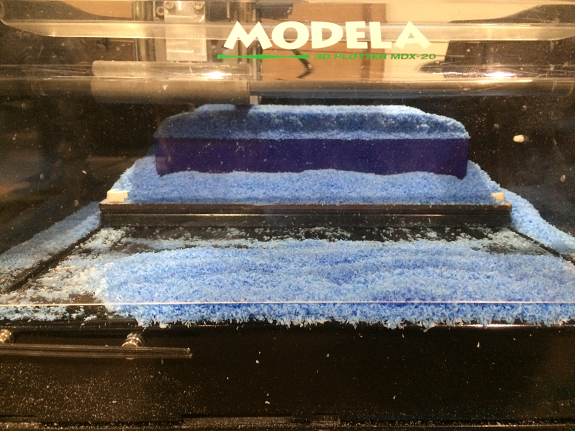
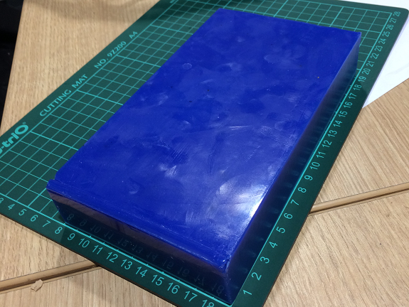
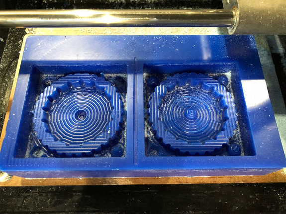
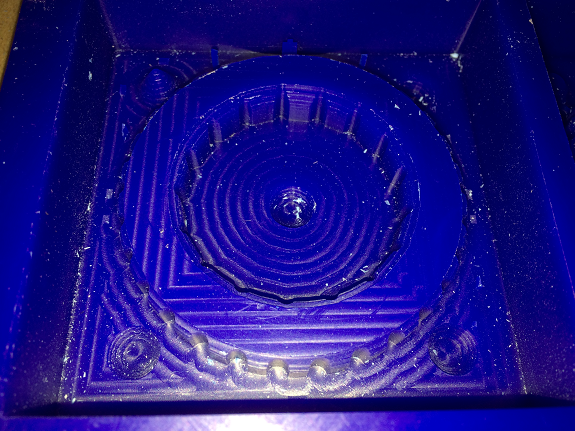
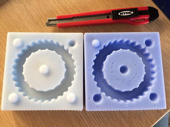
This image shows the wax mold after the first milling stage.
The surfaces look smooth, although the shapes are still square.
The surfaces look smooth, although the shapes are still square.
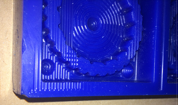
Here we see an approach to a part of the mold.
In the second stage, I changed the flat tip milling bit to the round tip bit.
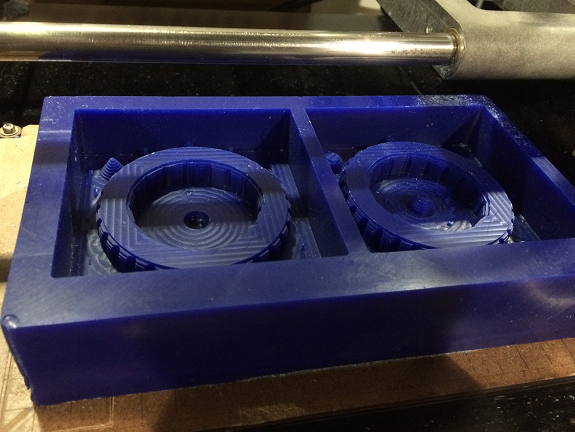
After 36 minutes passed, I got the finished mold.
It still has square details. This is because I should have used a thinner milling bit like 1/16 ", but we do not have one long enough to reach the bottom of the mold.
It still has square details. This is because I should have used a thinner milling bit like 1/16 ", but we do not have one long enough to reach the bottom of the mold.
3. Make the silicone mold.
Cautions

Gloves should be worn to avoid contact with silicone or catalyst, it is very sticky.
I recommend using an apron or some protector to prevent the silicone from falling on clothes.
I recommend using an apron or some protector to prevent the silicone from falling on clothes.
With the blue wax mold, the next step is to make the silicone mold.
Materials and equipment needed
Materials and equipment needed
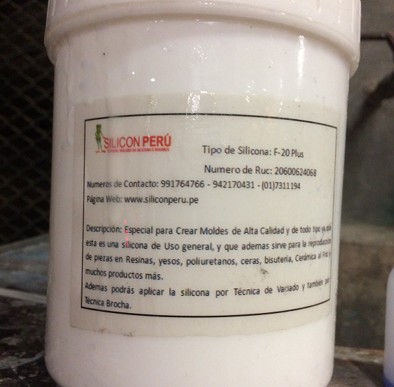
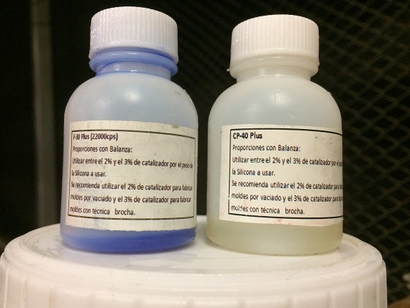
- Silicone type F-20 Plus
- CP-40 Plus catalyst
- A pair of gloves
- A balance to weigh
- Plastic cups
- Tongue depressor
I did not have enough catalyst for both molds so I used another one with similar characteristics.
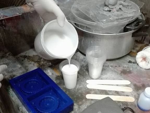
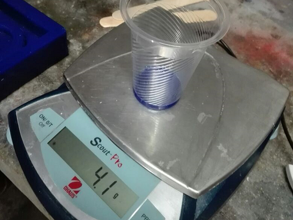
I filled a 5 ounce plastic cup with Silicone F-20 Plus.
The glass with the silicone weighed 138.5 grams.
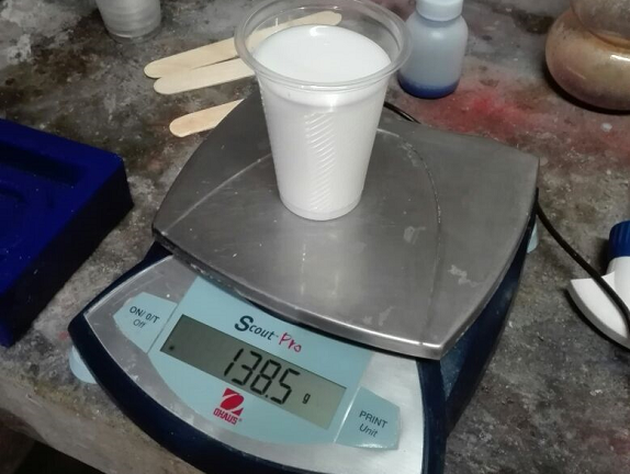
According to the instructions, 3% by weight of the Catalyst should be used.
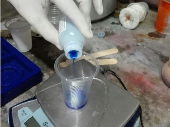
Then I mixed the silicone with the catalyst with a tongue depressor.
The mixture must be made slowly to avoid the formation of air bubbles, but not so slow as it could solidify before emptying it into the mold.
It must be completely mixed, because the silicone parts without catalyst will never solidify.
The mixture must be made slowly to avoid the formation of air bubbles, but not so slow as it could solidify before emptying it into the mold.
It must be completely mixed, because the silicone parts without catalyst will never solidify.
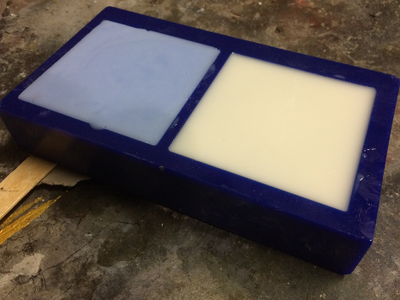
I emptied the silicone mixed with the catalyst in one of the molds,
then I repeated the process for the second mold, this I did with the yellow catalyst.
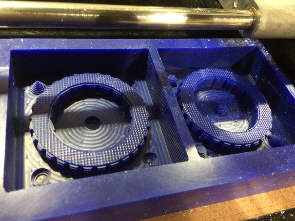
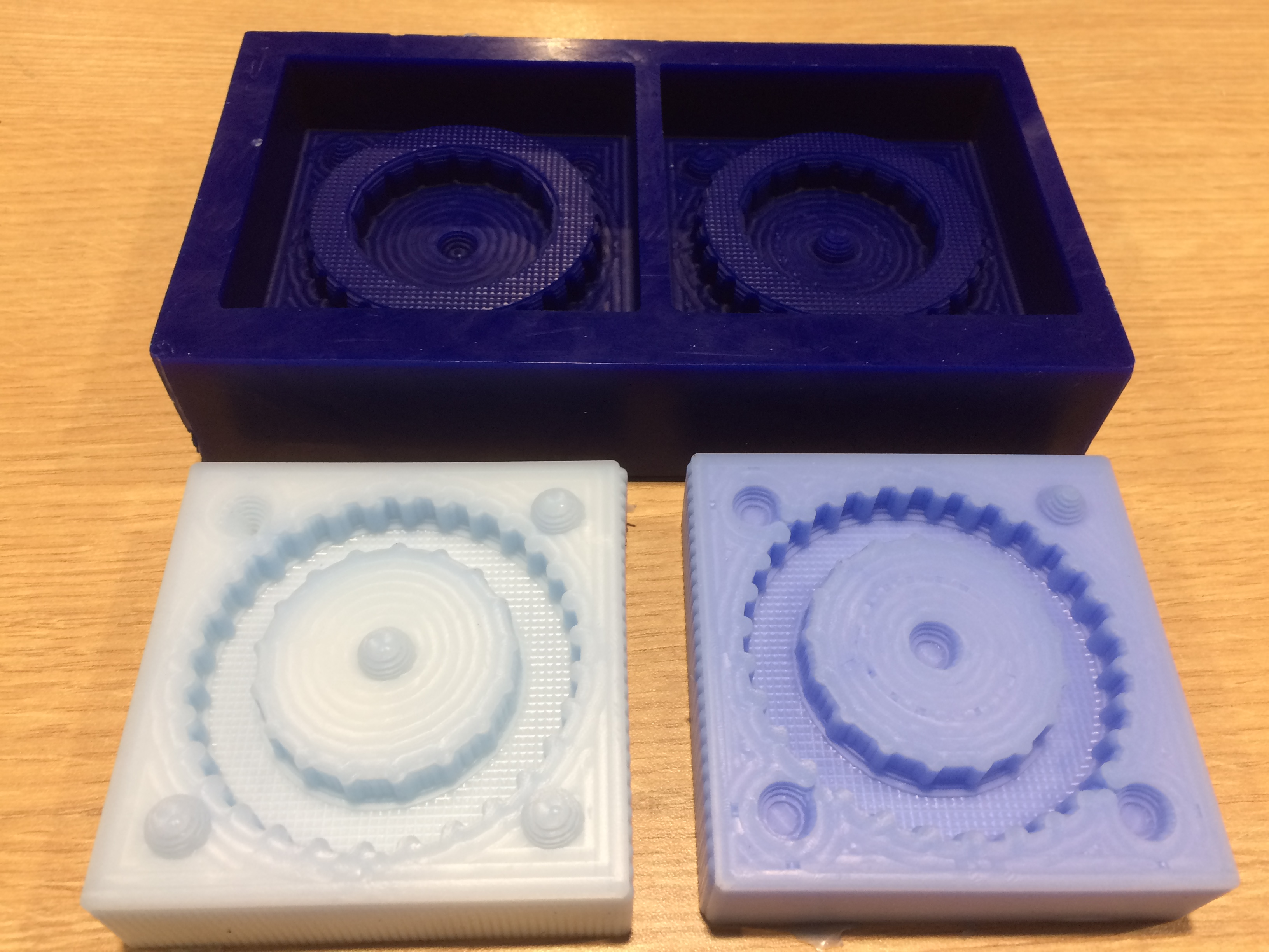
In this image both molds are filled with silicone.
In this image both molds are filled with silicone.
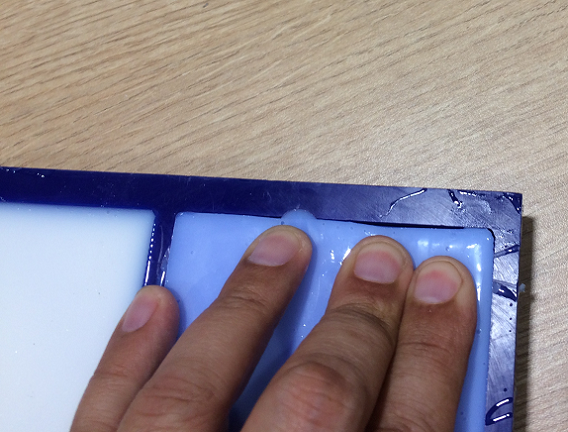
This silicone takes 20 minutes to solidify, although I left it until the next day.
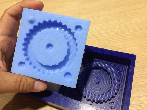
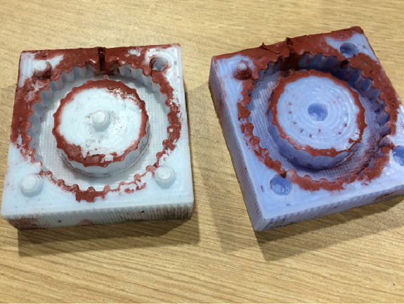
After a while, the silicone was already solid and easily detached from the mold.
After a while, the silicone was already solid and easily detached from the mold.
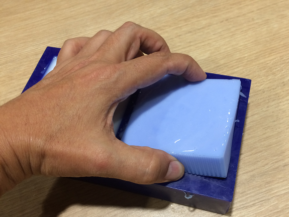
I removed the silicone from both molds. No residue left, the mold was clean.
The silicone mold was ready for the next stage.
The silicone mold was ready for the next stage.
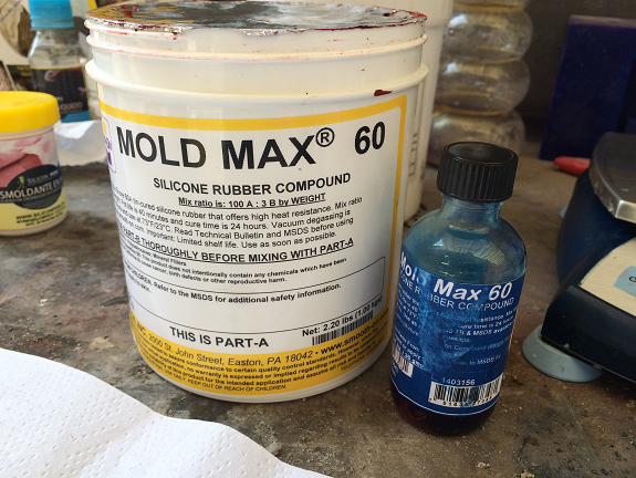
4. Make the tire.
To make the tire I used Mold Max 60 Silicone rubber compound and its catalyst.
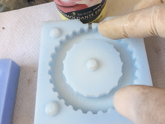
To prevent the silicone rubber compound from sticking to the silicone mold I used paste release agent.
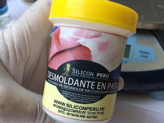
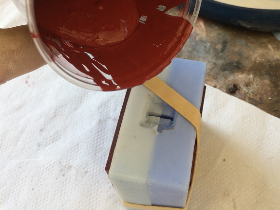
To be able to empty the silicone rubber compound, I made a cone shape cut on one side of the mold
I applied the mold release agent inside the mold and on the faces that are in contact.
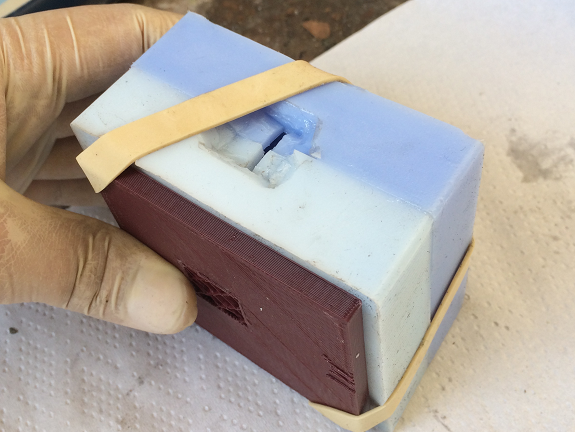
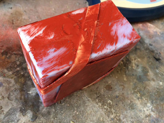
Then I secured the molds with a rubber band and some pieces of rigid plastic to prevent the mold from deforming.
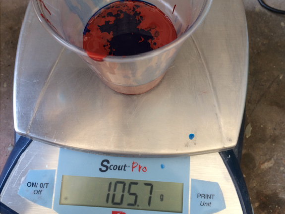
I filled a plastic cup with 102.7 gr of silicone rubber compound.
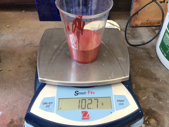
Then, in the same glass I added 3% of the catalyst.
The emptying took about 15 minutes, the hole was very small and the silicone was beginning to solidify.
It was necessary to give the mold some blows so that the bubbles could come out.
It was necessary to give the mold some blows so that the bubbles could come out.
The instructions say that the curing time is 24 hours.
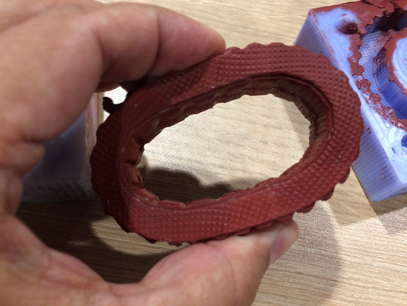
After 24 hours, I removed the rubber band and separated both parts of the mold.
It came off easily, due to the release paste.
It came off easily, due to the release paste.
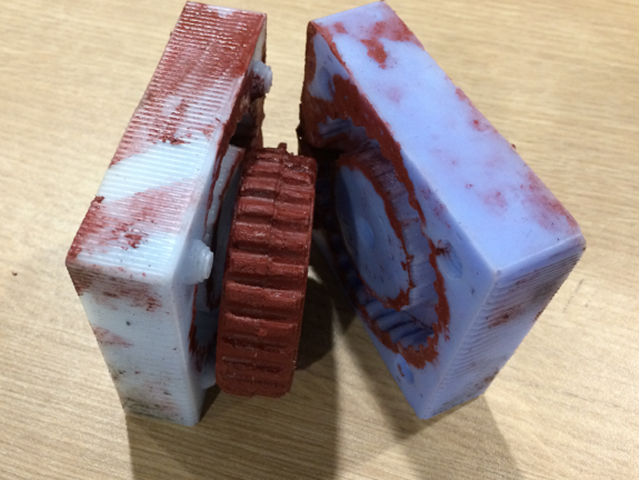
The tire has some small bubbles and a burr that I removed with a cutter
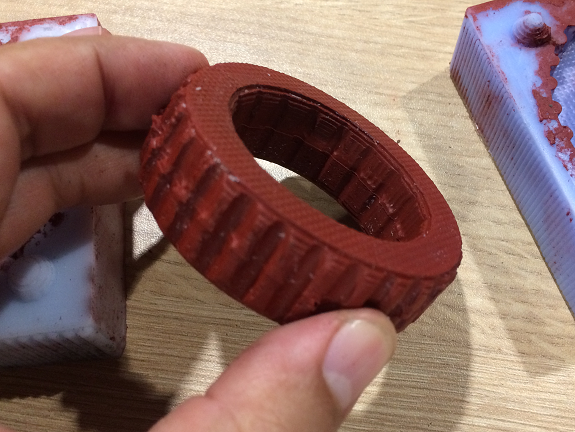
The tire is flexible, does not lose its shape and does not crack when pressed.
In the mold was some silicone, I think I did not use enough paste to unmold.
5. Make the wheel for tire test.
I exported the Rim as an STL file and I opened it with the BCN3D Cura software, in this picture you can see how it will make the filament layers.
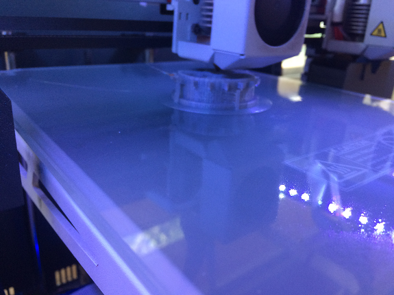
In the next two images, the control screen of the 3D printer and the start of the print job.
In the next two images, the control screen of the 3D printer and the start of the print job.
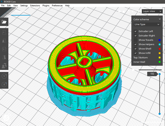
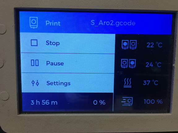
The 3D printing of the rim took 3 hours 56 minutes, I used PLA filament of 2.85 mm. selecioné infill pattern Cubic, density 40%.
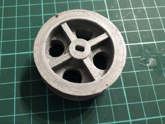
In this image the reliefs are seen so that the tire does not slip in the rim.
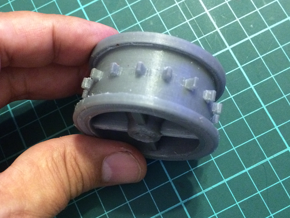
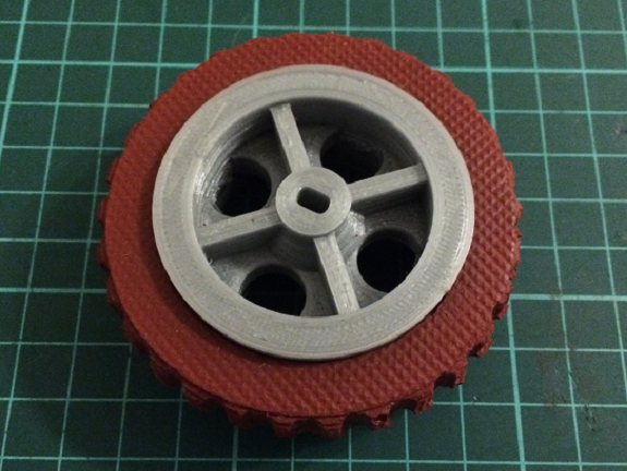
Here we can see the design of the complete wheel and compare it with the rim (made with 3d printing) and the rubber silicone tire made by molding.