Week 10
Input devices
This week's theme was: "Input Devices", where we already apply the knowledge and skills acquired in the previous weeks and we investigate on sensors that allow us to capture information about the environment so that an electronic device can do something.
What I researched and learned this week was very helpful for my final project.
The objective of this assignment were:
What I researched and learned this week was very helpful for my final project.
The objective of this assignment were:
- Measure something: add a sensor to a microcontroller board that you have designed and read it
Of the many sensors that we have seen, I decided to make a proximity sensor, since for my final project this type of sensors is necessary to detect objects or barriers that are approaching and changing the course.
I used as base the PCB that I made in the assignment "Electronic Design" and in "Embedded Programming".
I used as base the PCB that I made in the assignment "Electronic Design" and in "Embedded Programming".

My workplan was as follows:
1. Design the PCB.
For the schematic diagram, use as my basis the diagram of the "Embedded Programming" assignment.

This is the schematic diagram, it includes a pair of LEDs to show alerts if the object is approaching.

This is my component diagram. The next step is to export as a PNG image at 500 dpi and monochromatic.

2. Milling the PCB.
This is the list of components for weld on the PCB.
- 1 ATtiny44 microcontroller
- 1 20MHz resonator
- 1 resistance 10K smd
- 1 capacitor 1uF smd
- 1 pin header 2x3
- 1 pin male 1x4
- 1 pin male 1x6
- 2 resistances 499 ohm smd
- 1 red led smd
- 1 yellow smd led
- 1 PCB 2x3 "
- 1 milling bit 1/64 "
- 1 drill bit 1/32 "

I loaded the file with the strokes in the program, and sent it to mill. The work was planned for 20 minutes.

Do not forget
The milling bit must be well adjusted, otherwise the movement will loosen and fall, breaking the tiny tip.
The milling bit must be well adjusted, otherwise the movement will loosen and fall, breaking the tiny tip.

Bad idea # 2
After doing a broken bit, I wanted to try another way. So I tried to cut the circuit on a sheet of adhesive copper with the Roland vinyl cutter.
The result was disastrous, I had to edit the file so that the tracks are thicker, and to adjust the pressure of the blade on the copper sheet.
After doing a broken bit, I wanted to try another way. So I tried to cut the circuit on a sheet of adhesive copper with the Roland vinyl cutter.
The result was disastrous, I had to edit the file so that the tracks are thicker, and to adjust the pressure of the blade on the copper sheet.


Finally, I finished milling the PCB, next time, I'll be more careful.

3. Components weld.
I started by soldering the ATtiny44 microcontroller, first I fastened it with a pair of tweezers and welded a leg so it would not move, then I applied tin to the others.

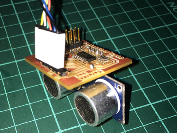
In this view you can see with more detail the components welded to the PCB, only the ultrasound sensor is missing.

To welder the ultrasound sensor I used a 1/32 "Dremel drill bit

4. Programming of the PCB.
I connected my new PCB with the sensor to my FabISP programming board and both to the computer.

For the programming, the numbering of the pins was made using this table as a guide.
| Function | #pin | #Arduino |
|---|---|---|
| Trigger | 5 (PB2) | 8 |
| Echo | 6 (PA7) | 7 |
| Led1 | 10 (PA3) | 3 |
| Led2 | 11 (PA2) | 2 |
| Rx | 12 (PA1) | 1 |
| Tx | 13 (PA0) | 0 |

This is the program that I used to test the functioning of the sensor. The distance readers send them to the serial port.
#include <SoftwareSerial.h>
const byte rxPin = 0; // pin12 PA1 -->1 analog input 1
const byte txPin = 1; // pin13 PA0 -->0 analog input 0
int trigger =8 ; // pin5 PB2 -->8 PWM
int echo =7 ; // pin6 PA7 -->7 analog input 7
int led1=3; //pin10 -->3 analog input 3
int led2=2; //pin11 -->2 analog input 2
SoftwareSerial mySerial(rxPin, txPin);
long distancia;
long tiempo;
void setup(){
mySerial.begin(9600);
pinMode(trigger, OUTPUT); /*activación del pin 9 como salida: para el pulso ultrasónico*/
pinMode(echo, INPUT); /*activación del pin 8 como entrada: tiempo del rebote del ultrasonido*/
pinMode(led1,OUTPUT);
pinMode(led2,OUTPUT);
digitalWrite(led1, LOW);
//delay(1000);
//analogWrite(led2,HIGH);
//analogWrite(led1,LOW);
//delay(1000);
//analogWrite(led2,LOW);
mySerial.println("Ready......");
}
void loop(){
digitalWrite(led1,!digitalRead(led1));
digitalWrite(trigger,LOW); /* Por cuestión de estabilización del sensor*/
delayMicroseconds(50);
digitalWrite(trigger, HIGH); /* envío del pulso ultrasónico*/
delayMicroseconds(50);
tiempo=pulseIn(echo, HIGH);
/* Función para medir la longitud del pulso entrante. Mide el tiempo que transcurrido entre el envío
del pulso ultrasónico y cuando el sensor recibe el rebote, es decir: desde que el pin 12 empieza a recibir el rebote, HIGH, hasta que
deja de hacerlo, LOW, la longitud del pulso entrante*/
distancia= double(tiempo * 10 / 292 / 2); /*fórmula para calcular la distancia obteniendo un valor entero*/
/*Monitorización en centímetros por el monitor serial*/
mySerial.print("Distancia ");
mySerial.print(distancia);
mySerial.println(" cm");
delay(1000);
}
5. Test run.
This is the performance test I did, you can see how the sensor's return values change as an object moves in front of it.
Files to download
 UltrasonicSensor.ino