Week 3
Computer-controlled cutting
This week we have learned to use the laser cutter and the vinyl cutter. These tools will be very useful for the final project. First we must prepare the files with the respective designs.
The objective of this assignment were:
- Cut something on the vinylcutter.
- Design, lasercut, and document a parametric press-fit construction kit, accounting for the lasercutter kerf, which can be assembled in multiple ways.
My Workplan
My workplan was as follows:
1. Vinil Cutting.
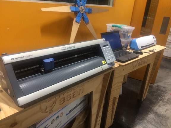
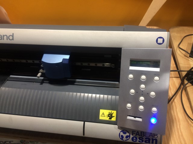
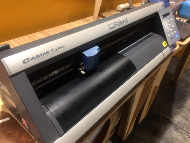
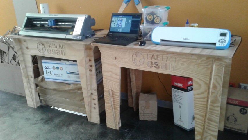
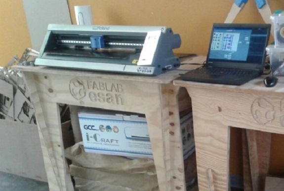
The vinyl cutting machine with which I will work is the "Roland's CAMM-1 Servo"
It is a plotter with a blade that moves by a shaft of 70cm long, has rollers that move the vinyl roll forward and backward allowing the blade serious any form.
Here we have a video explaining its use https://www.youtube.com/watch?v=f-0hViMnrzI
And this for the installation
https://www.youtube.com/watch?v=a7huuzGMHPk
And this for the installation
https://www.youtube.com/watch?v=a7huuzGMHPk
Cautions
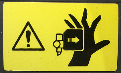
We must be careful when operating the vinyl cutter, because it has a very sharp blade.
When in operation, the blade holder moves horizontally very fast and could hit or cut the operator's hand or catch a finger
When in operation, the blade holder moves horizontally very fast and could hit or cut the operator's hand or catch a finger
Design in Photoshop
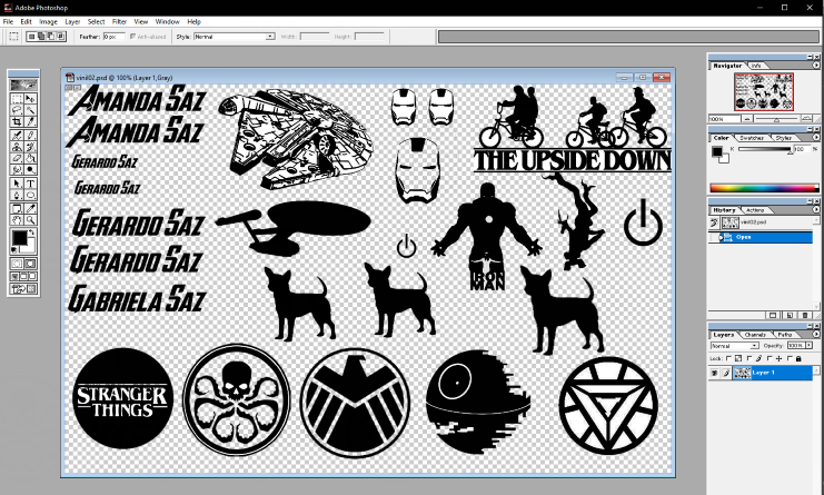
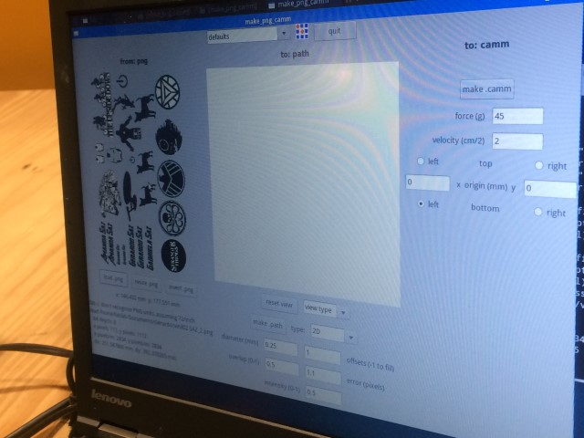
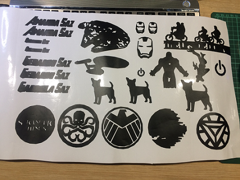
Without much time to research, I prepared a test sheet with some figures that I found on the internet in Adobe Photoshop. I saved the file in PNG format.
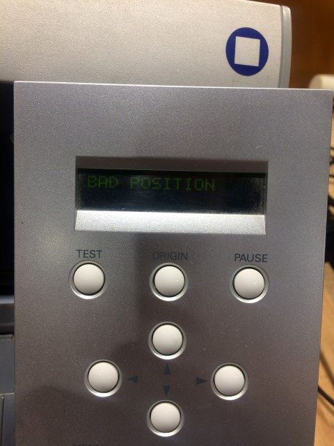
In the vinyl cutting machine, the first thing to do is secure the material for the cut, for this we must place the stops at the ends of the material, here you can see some pictures placing the material and placing the stops in the wrong way. The cutter notices the error and displays a "BAD POSITION" message.
In the vinyl cutting machine, the first thing to do is secure the material for the cut, for this we must place the stops at the ends of the material, here you can see some pictures placing the material and placing the stops in the wrong way. The cutter notices the error and displays a "BAD POSITION" message.
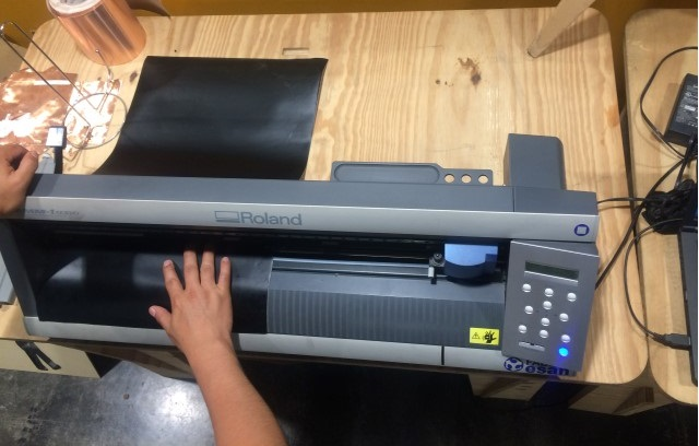
I noticed that there are certain positions for the stops that are marked in another color, it is in those places where the stops must be established. Again, I tried. In this second chance the cutter made a stop motion butt and showed a message indicating the width of the material to work.
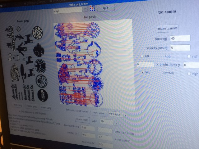
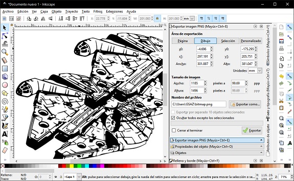
Without more than adjusting I loaded the file with my designs in the software of the cutter. In the following images you can see the newly loaded designs and the route map that the cutter will make (blue for the cut and red for the displacement).
Without more than adjusting I loaded the file with my designs in the software of the cutter. In the following images you can see the newly loaded designs and the route map that the cutter will make (blue for the cut and red for the displacement).
It started cutting the vinyl according to plan.
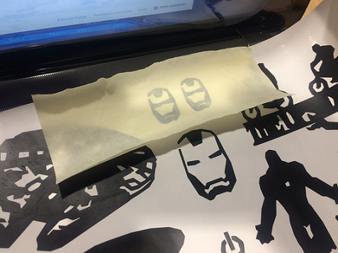
As soon as it finished I removed the material and I noticed that the work was what I expected, no cuts were made in the parts with small details and in other places there was no cut. Only the simple images were cut well.
As soon as it finished I removed the material and I noticed that the work was what I expected, no cuts were made in the parts with small details and in other places there was no cut. Only the simple images were cut well.
Learned lessons
I checked the file I prepared in Photoshop and noticed that the edges of the images weren’t defined.
The images must be formed only by lines and curves, only contours.
I will chose a figure to redesign it and return to the cutter.
The images must be formed only by lines and curves, only contours.
I will chose a figure to redesign it and return to the cutter.
Design in Inkscape (Second try)
I discovered that the problem with Photoshop is that it is not ready to work with vector graphics.
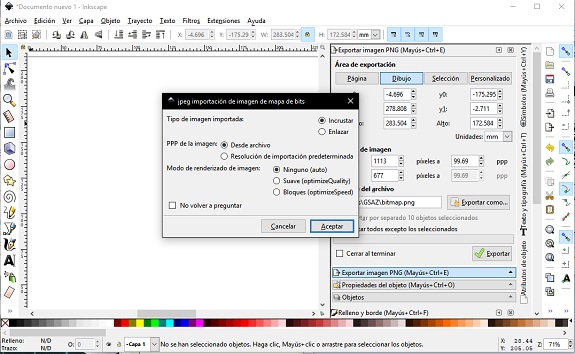
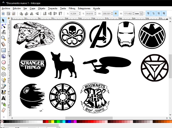
So, I decided to do the test with Inkscape, in the main menu "File", I selected "Import".
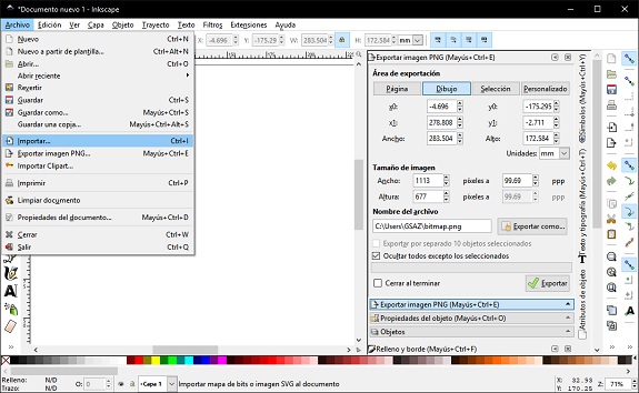
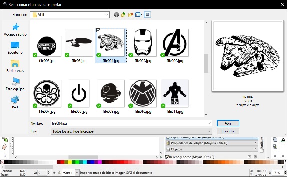
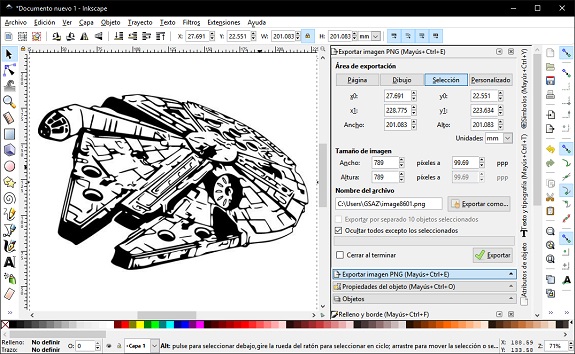
I looked for the images that I already had separated, and I imported it.
Then a dialog box appeared. I did not make any changes to the selected elements. since in this case it suits me that the image is not linked to any external file.
Then a dialog box appeared. I did not make any changes to the selected elements. since in this case it suits me that the image is not linked to any external file.
The software of the Roland vinyl cutter needs the images to be in PNG format, but not any PNG, but one of vector graphics.
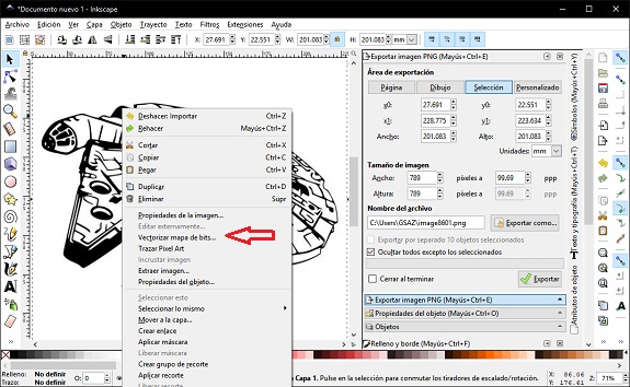
Inkscape can convert bitmap images to vector graphics, to get it you just have to right click on the image and select "Vectorize bitmap ...".
Inkscape can convert bitmap images to vector graphics, to get it you just have to right click on the image and select "Vectorize bitmap ...".
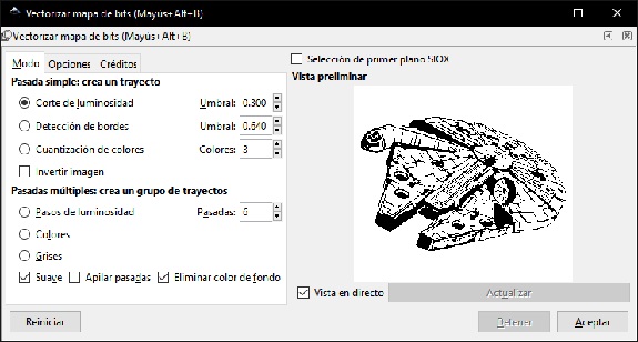
Then, a dialogue box was opened with several conversion alternatives. I used "Lightness cut" with threshold = 0.3
Then I clicked on the "Accept" button and closed the dialog box. What I got were two images, one of them is the original bitmap and the other the vector image (I moved the images so they can be seen).
Then I clicked on the "Accept" button and closed the dialog box. What I got were two images, one of them is the original bitmap and the other the vector image (I moved the images so they can be seen).
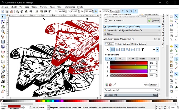
To determine which is the vector image, I selected both and in the properties area of the objects I changed the color of the fill to red. The image that did not change color is the one of bitmap, that image I eliminated it.
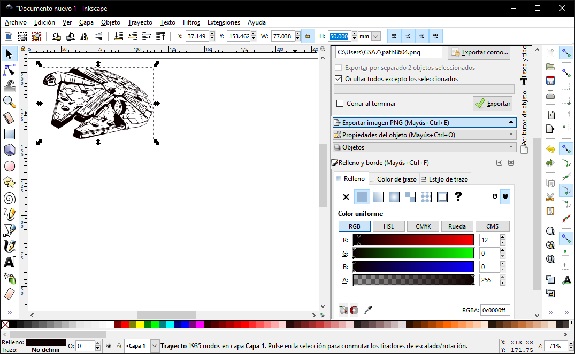
I relocated the vector image and changed its size, in the upper part there is a bar of controls of size and scale, mark the padlock so that the proportions do not change when reducing it.
I relocated the vector image and changed its size, in the upper part there is a bar of controls of size and scale, mark the padlock so that the proportions do not change when reducing it.
I followed the same procedure with the other images.
Then I exported the file with PNG format.
Files to download
Then I exported the file with PNG format.
Files to download
Vinil Cutter
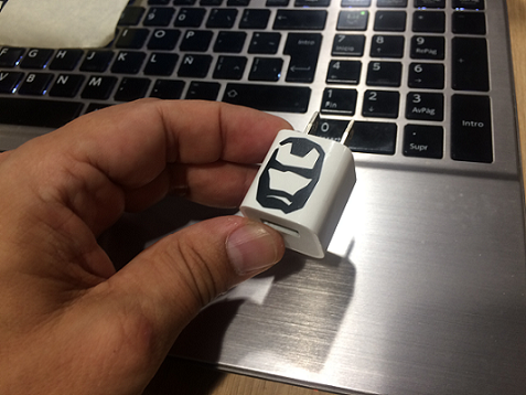
With the new design of vector images and in PNG format, I went to the Roland vinyl cutter.
2. Laser Cutting.
Previous experiences
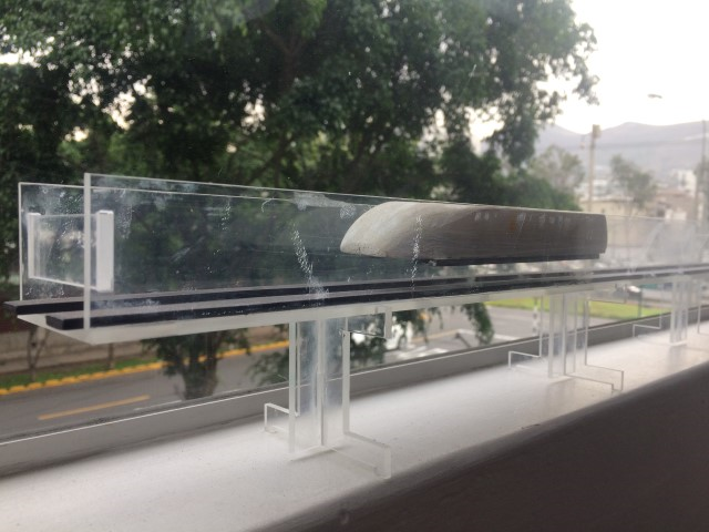
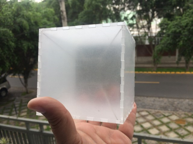
A few months ago, I had commissioned laser cutting jobs near my house. The first one was to help my oldest daughter in her science fair work (magnetic levitation train). The second is a cube-shaped lamp (the tesseract), still unfinished.
A few months ago, I had commissioned laser cutting jobs near my house. The first one was to help my oldest daughter in her science fair work (magnetic levitation train). The second is a cube-shaped lamp (the tesseract), still unfinished.
To do both I was asked for a file with the design, due to this reason I learned the basics of AutoCAD. I must say that, at that time, I did not know anything about the press-fit, it was enough for me that the pieces fit in, because my final objective was to paste them later
The Laser machine:
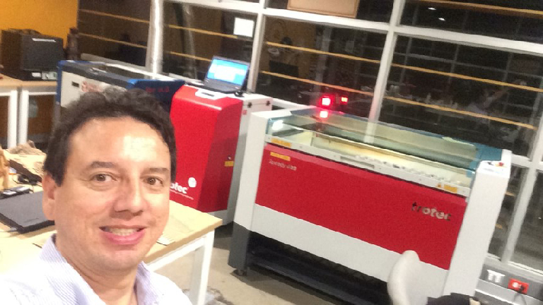
The laser cutter with which we will work is the "Trotec Speedy 400".
www.trotec.com.
It is used to cut silhouettes in sheets or engrave the surface of rubber, acrylic, coated metal, tin, special steel, anodized aluminum, cork, cardboard, glass, leather, marble, various plastics and wood (MDF, plywood, etc.)
It is used to cut silhouettes in sheets or engrave the surface of rubber, acrylic, coated metal, tin, special steel, anodized aluminum, cork, cardboard, glass, leather, marble, various plastics and wood (MDF, plywood, etc.)
The main components of the machine are:
- Laser Cutter Head, responsible for directing the laser beam that has a wavelength of 10.6 μm (infrared) and is invisible, so to help center the cut also has a red laser guide.
- Special table with a grill made of metal material in the shape of honeycomb of variable height, works in combination with a gas aspiration system.
- Travel rails, the cutting head shifts on them
- Toxic gas extraction and filtering system
Cautions

Due to the high density of laser light it is highly dangerous to the eyes or body parts. For that reason, it is advisable to use safety glasses and keep the machine cover closed.
Certain materials can release toxic vapors and dust. Due to this situation, the cutter cover must remain closed until all gases and dust are removed.
The work:
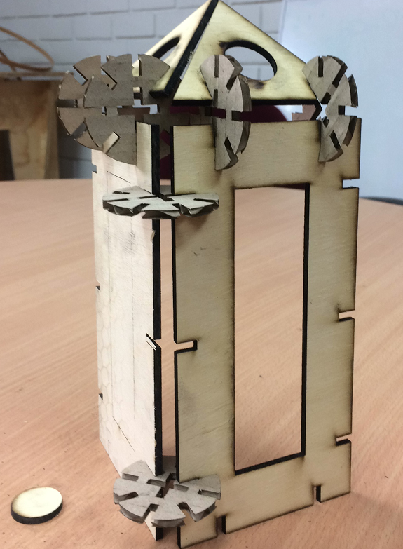
I want to make a construction kit of flat pieces that can be used to build houses or castles, etc. I did a previous design in Rhinoceros.
I want to make a construction kit of flat pieces that can be used to build houses or castles, etc. I did a previous design in Rhinoceros.
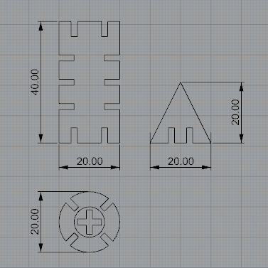
I will make rectangular, square, triangular and circular shapes, all with grooves that allow connecting with each other and with measures that can change depending on the thickness of the material. For the design I will use Rhinoceros with the Grasshopper plug-in, which is a tool for parametric design.
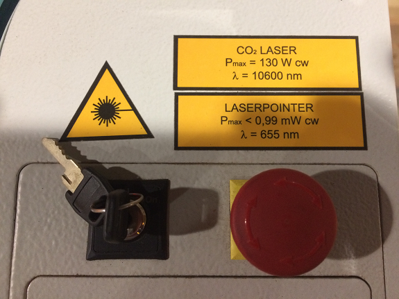
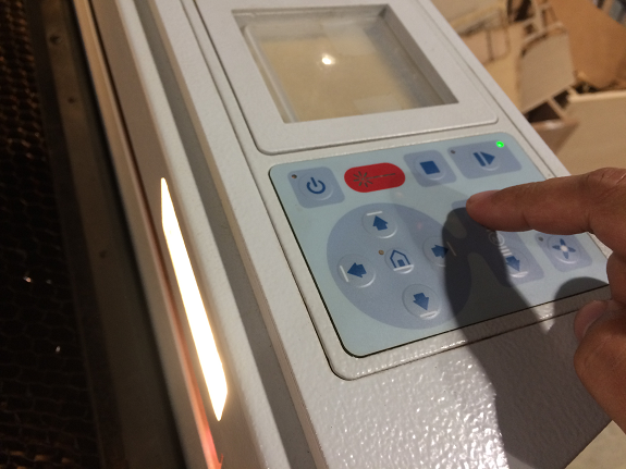
Control panel - On / off - Emergency stop
To turn on the Laser Trotec Speedy 400 cutter, the ignition key must be located, it is on the control panel, on the right side.
In the image we can see the key put in its place to turn it on, you must turn the key in the clockwise direction, as if you were lighting a car.
At that moment the air circulation system is activated and the cutting platform moves downwards.
In case of an emergency, just press the red button and immediately the cutter will stop working.
In case of an emergency, just press the red button and immediately the cutter will stop working.
The Laser lens moves from left to right and from top to bottom while it is operating. When it is stopped, its movement can be controlled from the control panel.
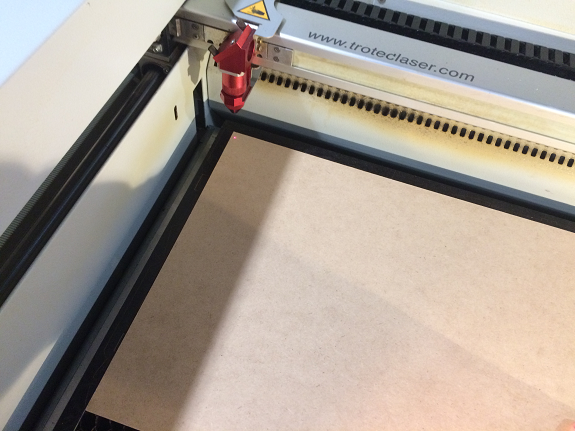

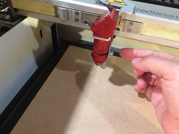
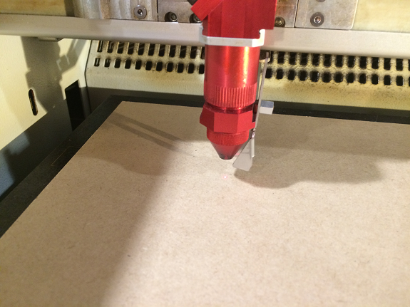
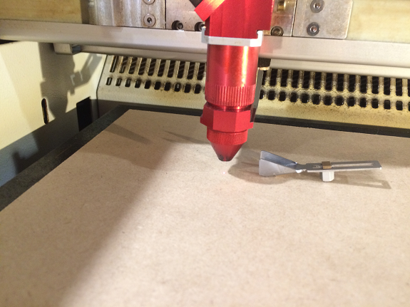
Calibration vertical axis
The laser lens is designed to operate at a certain distance from the cutting surface, for this a metal element is required to be placed on the pointer, then using the command buttons on the control panel, the cutting platform is raised With the material to be cut, be careful when climbing, since the calibrated distance is when the metal element touches the surface and falls off the pointer.There are other laser cutters that have a self-calibration system like the Epilog
With the calibrated laser cutter, I focused on the design of the pieces
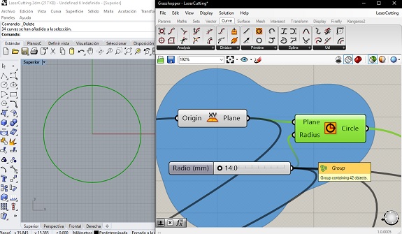
Parametric Design
I started by designing the pieces using "Parametric Design", in this way, I can make changes in the press-fit depending on the thickness of the material and the dimensions.
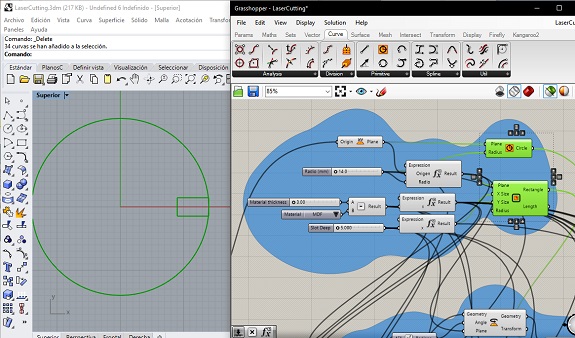
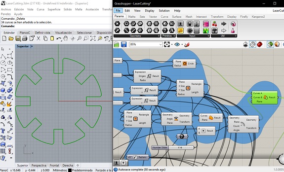
For this I used Rhinoceros Grasshopper. In this image shows the initial design of a circle of 14 mm radius in the coordinates (0,0).
I started by designing the pieces using "Parametric Design", in this way, I can make changes in the press-fit depending on the thickness of the material and the dimensions.
For this I used Rhinoceros Grasshopper. In this image shows the initial design of a circle of 14 mm radius in the coordinates (0,0).
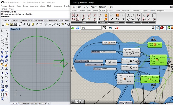
The circular piece that I designed joins others through cuts of the thickness of the thickness of the material, in this case 3mm, here we see the use of the "Rectangle" component with the necessary dimensions and location.
I did not want that at the moment of obtaining the circular figure it has edges, that's why I added a bevel, for it I created a square, I placed it on the edge of the circle and I turned it 45 °
With the component "Region Union" I joined the two parts in a single figure.
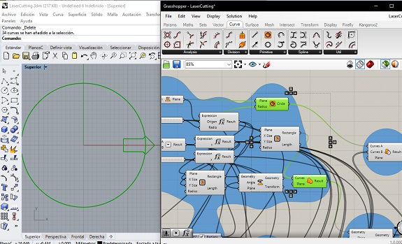
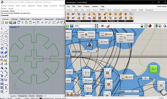
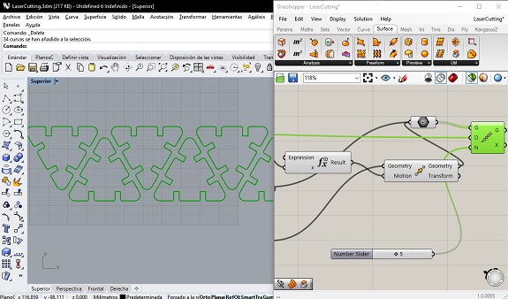
With the "Array Polar" component, I created copies of the figure and rotated them around the center, as it is parametrizable, I can decidor increase the number of figures and then cut them to the circle.
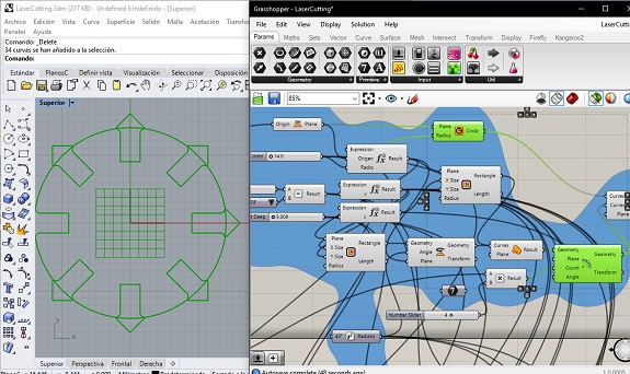
With the component "Region Difference" I cut out of the circle the figures that I created
Following the same technique, I added a hole in the center in the shape of a cross.
with the "rectangular array" tool create several copies of the same figure in rows and columns. These rows and columns are parametrizable.
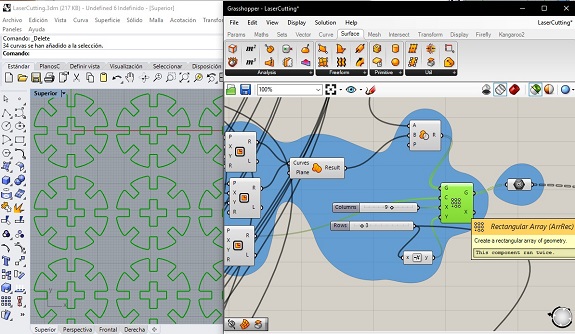
I proceeded in the same way as described above with a figure of rectangular shape.
I increased a Voronoi figure to later record it on the rectangular figure, for that I used the "Voronoi" component, as parameters are added to the figure and a region populated point in random positions.
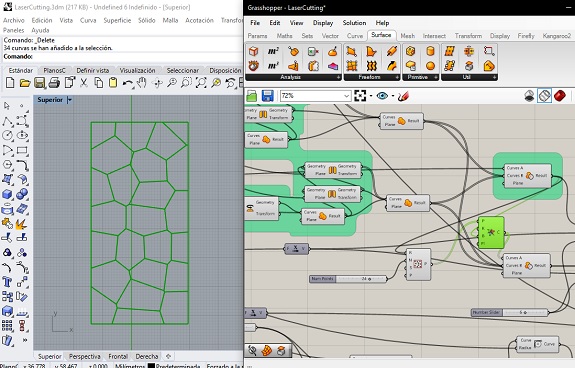
In this image you can see the rectangular figure with the cuts for press-fit and a Voronoi engraving on it.
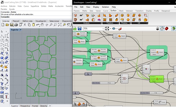
With the "Linear Array" component, I created several copies of the same figure.
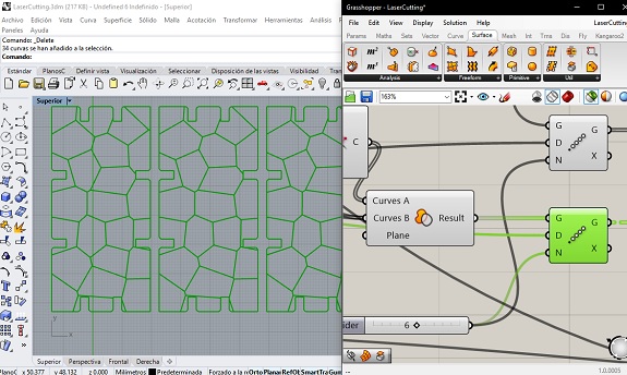
Finally, I made a parametric triangular figure, also with press-fit cuts
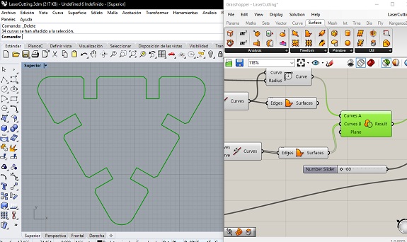
This triangular figure, I also duplicated it several times.
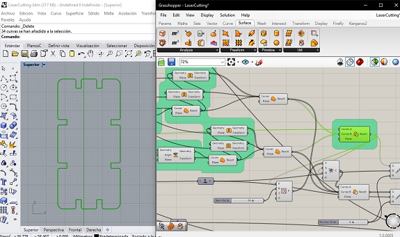
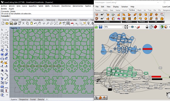
Here, on the left you can see all the figures projected to Rhinoceros. And to the right a view of all the parametric elements that the figures generated.
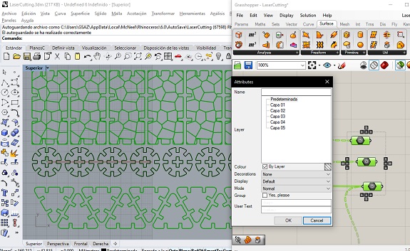
To make the figures permanent, the "Bake" component is used, the figures created are no longer parametric.
As I worked on the upper plane, the resulting figures are flat and it is not necessary to project them to the horizontal plane with the Make2D command.
As I worked on the upper plane, the resulting figures are flat and it is not necessary to project them to the horizontal plane with the Make2D command.
I selected the figures in Rhino and exported them in DXF format, to then open them in CorelDraw
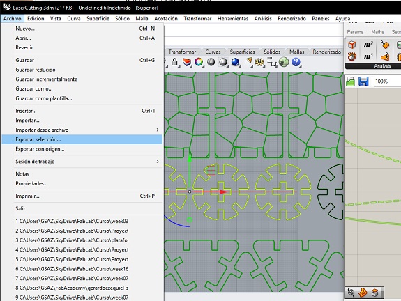
I opened the DXF file in CorelDraw to cut it in the Trotec laser cutter.
Here you can make some adjustments, such as re-locating, duplicating or deleting some figures.
Here you can make some adjustments, such as re-locating, duplicating or deleting some figures.
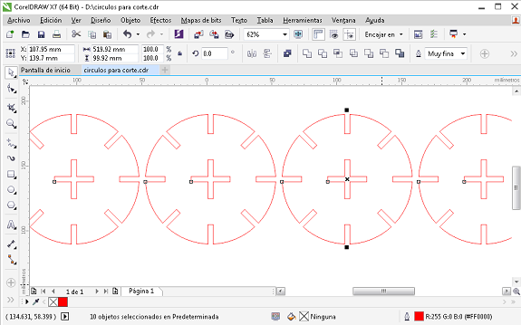
For the Trotec, the definition of cut is: "Very thin" lines and in red color, for engraving "very fine" lines and in black color.
Video
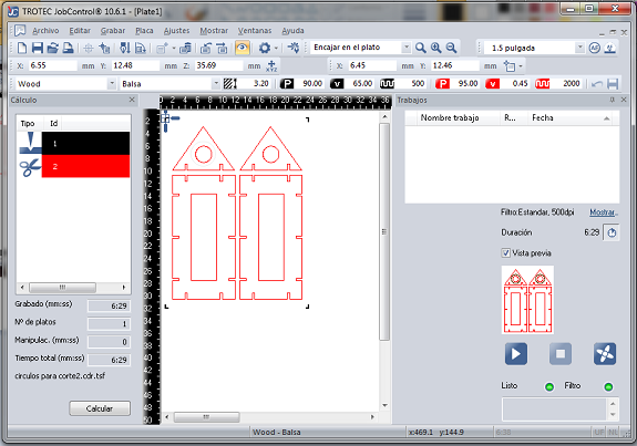
In this video I did it by cutting the circular figures in corrugated cardboard.
In this video I did it by cutting the circular figures in corrugated cardboard.
In this video, the Laser Trotec cutter is making an engrave of some Voronoi figures on the MDF.
This is a sample cut in corrugated cardboard and plywood.
Files to download