Mechanical Design, Machine Design
Have you:
- [x] Explained your individual contribution to this project on your own website
On the group page, has your group:
[x] Shown how your team planned and executed the project
[x] Described problems and how the team solved them
[x] Listed future development opportunities for this project
[x] Included your design files, ‘hero shot’ photos of the machine and a short video of it operating
2018 Tiny G Controller Project
Design Files: Right Click + Save
As a continuing student, I asked to join the class at Dassault 3D Experience Lab. There, I collaborated on an automated Etch-A-Sktech.
The first issue was that the machine was very top heavy. This created a problem with the automation of the erasing process on the Etch-a-Sketch screen. The original design was that a motor on the Z-axis would flip the screen 180 degrees to erase any drawing. The problem with the machine being top heavy meant that gravity would pull the screen downwards. The majority of the time, a motor on the Z-axis would have to do work to hold the screen in place while the sketch was being rendered on the X and Y axes. After advice from Jean-Michel Molenaar, we considered adding a counter weight to the device. Placement became an issue, at that point. At the top of the device and behind the screen, the counter weight would continue the rotation. I brought up the physics of a Drinking Bird as a possibility to resolve the issue. Perhaps we could have used an hour glass shaped container with sand or fluid to help control the weight issue. Ultimately, the team resolved to install a manual lever due to the deadline. Future development plans for the machine still include a way to automate the erasing process on the Z-axis.
The second issue involved talking to the Tiny G controller to send code to automate the motors. The team could send individual moves to the controller through CoolTerm.
2015 Gestalt Board and Stage Project
Design Files: Right Click + Save
See also: Work done submitting the gestalt node to Seeed Studio
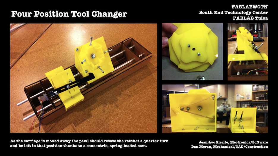
This is a group project that I worked on with Dan Moran, Fab Lab Tulsa. Using the instructions on the modular Machines that Make page, we built a single stage and planned for an end effector. Rather than have a single end effector, we decided to prototype a mechanical four-position tool.
The concept is to sacrifice some of the carriage’s travel distance to rotate a ratchet and swap tool heads.
Description from Dan:
“The lead screw will move the carriage to one of its limits where a ratchet on the carriage will engage a static pawl anchored to the stage housing. As the carriage is moved away the pawl should rotate the ratchet a quarter turn and be left in that position thanks to a concentric, spring-loaded cam. So by sacrificing a small portion of its overall travel to the ratcheting action, a single stage should now have the ability to use 4 times the tools.”
The build took several rounds of revisions in order to get the ratchet and pawl to engage reliably and stay in contact longer.
After several revisions, we improved on engagement by adding an additional rake to the pawl and ratchet.
The carriage will translate backwards towards the stepper motor to the engage the pawl attached to a platform screwed to the stage housing and as the carriage moves away, the pawl will rotate the face plate a quarter turn as controlled by the 4 lobe cam and rubber band powered cam follower.
We used #8 screws to illustrate tools.
We mounted the pawl assembly over the stepper motor end of the stage and put it through several manual cycles with my hands. Here are distances as measured from the pawl platform leading edge to the leading edge of the cardboard carriage (lead screw nut end) that would influence the range of the stage:
- 30 mm Pawl makes contact with ratchet (carriage moving toward pawl assy. and stepper motor)
- 33 mm Pawl seated in ratchet tooth (carriage moving away from pawl assy. and stepper motor)
- 70 mm Pawl clears ratchet tooth (carriage moving away from pawl assy. & stepper motor)
These distances were a little difficult to measure with much accuracy. The stage would loose at least 70mm of its range in the current design or potentially more since the pawl assembly can be mounted anywhere along the length of the lead screw.
Catching up with you on the software side of our machine. I have attached the code and a “path.csv” to manage the coordinates for moves.
The file can be executed by navigating to the directory and typing “python pawl.py” I’d probably copy this into /examples/htmaa. Wasn’t sure if there were any other dependencies. For this round, I did not include the bootloader.
Notes:
- I need to know the device ID of the FTDI cable on your end. I left it as the default: “/dev/ttyUSB0”. You can find the device by typing “ls /dev/tty.usb*”
- I noticed several threads come up that can be resolved by deleting the “test.vmp” file. I added that as our first step.
- Because we need to move the carriage from a home point, towards the motor and back; I wanted to do this in three moves to avoid errors. The first move takes the carriage back to home (70) in case of any power outage or interruption. The carriage then moves toward the motor (30) to engage the pawl. The final move (70) causes the pawl to rotate the face plate. These are set in the path.csv.
- I used Bas’s FABNET Bridge Board to test. Attached the traces.
- We can control the velocity of the moves, considering wear on the pawl and how quickly we want to make the change.
Sources
Moran, Dan "Machine Building" Message to Jean-Luc Pierite. 26 May 2015. E-mail.
Moran, Dan "Machine Design End Effector Update" Message to Jean-Luc Pierite. 2 June 2015. E-mail.
Pierite, Jean-Luc "Machine Design End Effector Update" Message to Dan Moran. 8 June 2015. E-mail.