Embedded Programming
Have you:
[x] Documented what you learned from reading a microcontroller datasheet.
[x] What questions do you have? What would you like to learn more about?
[x] Programmed your board
[x] Described the programming process/es you used
[x] Included your code
In order to start working on inputs and outputs for the final project I started to work on embedded programming. My first couple of attempts were with using the HUZZAH32 and flashing sketches through the Arduino IDE. After talking with Francisco at Beach Lab, I was convinced that I should work outside of the Arduino IDE and flash programs coded in C through the avrdude toolchain.
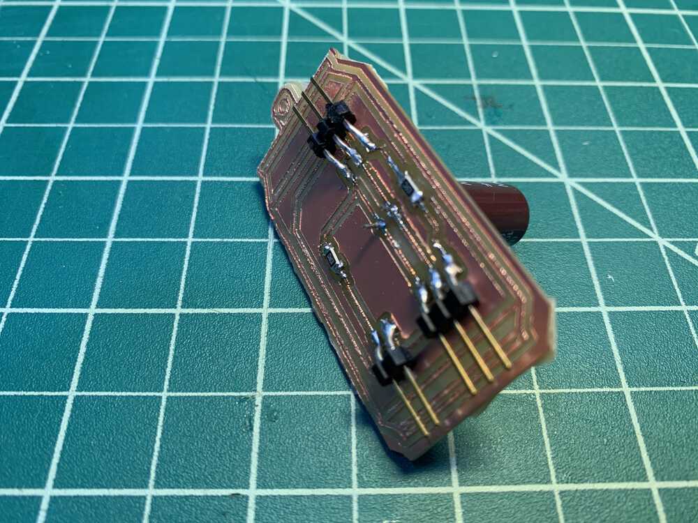
As discussed in Computer-Controlled Machining week, I added a strip of Neopixel LEDs to simulate grow lights for the Planetary Soda cabinet. I also added a fan to drying compartment. I designed a shield to connect both devices to the HUZZAH32.
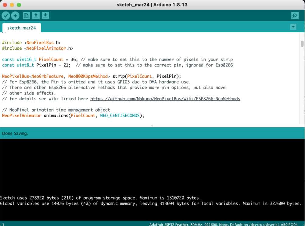
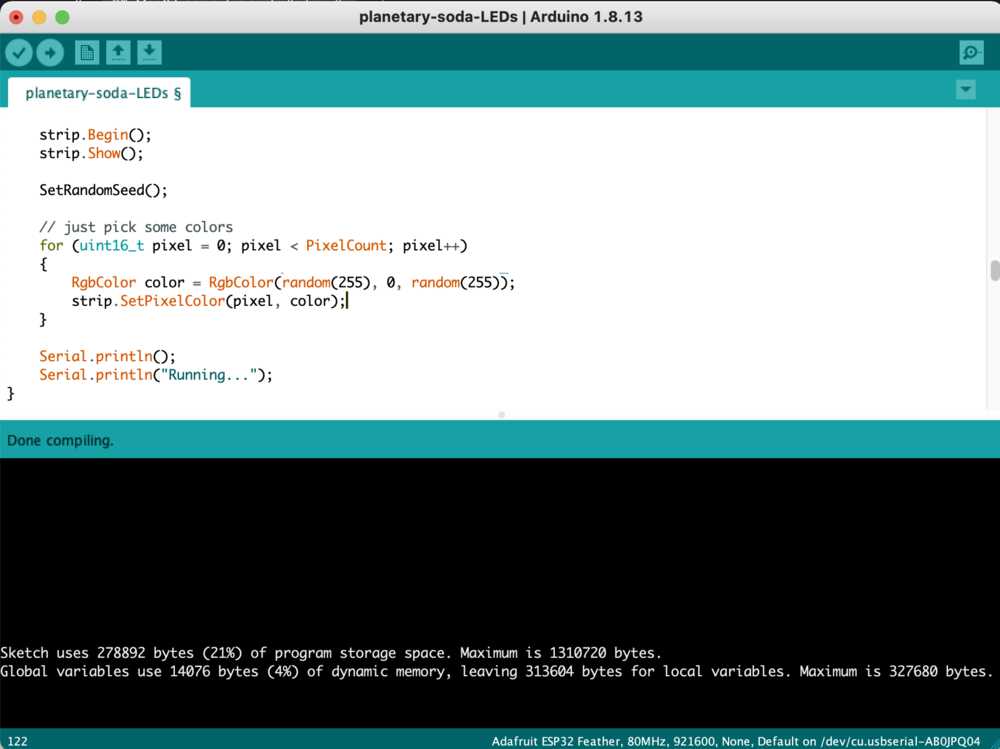
I then started with an example sketch, the main things to modify from the example were the number of LEDs and the pin which would communicate with them. Another change from the original example was to initialize each pixel with random colors, except any including a green value. The reason for this is because the spectrum is not conducive to photosynthesis. Therefore, I set the green to zero in both the setup function which is called at the beginning of the program and in SetupAnimationSet() which is called in the main loop. The sketch overall took up 21% of the storage space of the ESP32.
Design files: Right click + Save As
Design files: Right click + Save As
Going from the Arduino IDE into the avrdude toolchain, I programmed an ATTiny44 to flash the name of my final project “Abundance” to a 16x02 LCD through the SparkFun SerLCD v.2.5 backpack with PIC16F688.
Link to Output Devices week >>

Sending C code through AVR tools and testing through Arduino serial Monitor:
Breaking down Neil's code
I'm familiar with reading code through my experience writing HTML for websites and C++ for video game development.
This is the program from Neil's code it relies on definitions earlier in the file or in the includes. There are also specific data types that the code relies on to define variables.
The first data type is a char-acter. We see a variable chr created, followed by an array buffer[max_buffer]. max_buffer in Neil's code is a global which is a variable created outside of the main loop to allow for all functions defined in the file to use. max_buffer is hard coded to 25. The next data type is and int-eger. This holds whole numbers. The variable created is called index.
max_buffer at this point seems like a good candidate for changes.
int main(void) {
   //
   // main
   //
   static char chr;
   static char buffer[max_buffer] = {0};
   static int index;
CLKPR is the Clock Prescale Register defined in the ATTiny44 data sheet. Rahpael Schaad, provided a tutorial with a helpful breakdown on this point.
If we want to run at the full 8MHz and not mess with the LFuse, we simply set > CLKPR to divide by 1 in code:
CLKPR = (1 << CLKPCE);
CLKPR = (0 << CLKPS3) | (0 << CLKPS2) | (0 << CLKPS1) | (0 << CLKPS0);
From the data sheet:
The CLKPCE bit must be written to logic one to enable change of the CLKPS bits. The CLKPCE bit is only updated when the other bits in CLKPR are simultaniosly written to zero. CLKPCE is cleared by hardware four cycles after it is written or when the CLKPS bits are written. Rewriting the CLKPCE bit within this time-out period does neither extend the time-out period, nor clear the CLKPCE bit.
   //
   // set clock divider to /1
   //
   CLKPR = (1 << CLKPCE);
   CLKPR = (0 << CLKPS3) | (0 << CLKPS2) | (0 << CLKPS1) | (0 << CLKPS0);
The next bit of code initiatizes the outpins as Neil comments in the code. serial_port is defined globally as PORTA. Defined in the datasheet:
Port A is a 8-bit bi-directional I/O port with inte rnal pull-up resistor (selected for each bit). The Port A output buffers have symmetrical drive characteristics with both high sink and source capability.
serial_pin_out is defined as (1 << PA1). Writing logic one to enables the Analog to Digital Converter, Channel 1.
   //
   // initialize output pins
   //
   set(serial_port, serial_pin_out);
   output(serial_direction, serial_pin_out);
The integer variable index gets initialized to 0 just before the main loop. while loops will run while the condition passed is TRUE. As a Boolean type, the value of "true" is 1 and the value of "false" is 0. Because a 1 is passed into the while loop, this will be what runs on the processor after all is initialized.
   //
   // main loop
   //
   index = 0;
   while (1) {
get_char is a function defined earlier in the file. The first parameter passed is a reference to a global variable, serial_pins.
Regarding references or the ampersand before the variable: there are some helpful questions on stackoverflow regarding references and pointers, and stack and heap.
serial_pins is defined as PINA. From the datasheet,
As inputs, Port A pins that are externally pulled low will source current if the pull-up resistors are activated. The Port A pins are tri-stated when a reset condition becomes active, even if the clock is not running.
serial_pin_in writes logic one to PA0 which enables the Analog to Digital Converter, Channel 0.
We also pass a refrence to the character chr defined earlier in main.
get_char(&serial_pins, serial_pin_in, &chr);
In the definition of the function, we pass the reference to PINA as a pointer or memory address. We also pass the specific pin or PA0. We also have a pointer to the original chr variable.
There are some functions defined globally such as pin_test whihc "tests for the port pin."
bit_delay is defined globally with bit_delay_time set at 8.5 which is for 115200 baud rate for serial communication with overhead. bit_delay calls _delay_us which is defined in util/delay.h in the includes.
void get_char(volatile unsigned char *pins, unsigned char pin, char *rxbyte) {
   //
   // read character into rxbyte on pins pin
   //    assumes line driver (inverts bits)
   //
   *rxbyte = 0;
   while (pin_test(*pins,pin))
      //
      // wait for start bit
      //
      ;
   //
   // delay to middle of first data bit
   //
   half_bit_delay();
   bit_delay();
These are the includes. Before compiling the code, I made sure that each was available on my computer using the locate command in terminal. My current working laptop is an Intel Core 2 CPU T7200 @ 2.00 GHz x 2 running Ubuntu 16.04 LTS.
#include <avr/io.h>
#include <util/delay.h>
#include <avr/pgmspace.h>
The rest of get_char takes the 8-bit character and reads through each of the bits. It takes 10 bits to snd one character: a start bit, 8 data bits, and a stop bit. The data bits are read right-to-left. A helpful tutorial on Sparkfun brokedown how characters are sent and baud rate.
   //
   // unrolled loop to read data bits
   //
   if pin_test(*pins,pin)
      *rxbyte |= (1 << 0);
   else
      *rxbyte |= (0 << 0);
   bit_delay();
   if pin_test(*pins,pin)
      *rxbyte |= (1 << 1);
   else
      *rxbyte |= (0 << 1);
   bit_delay();
   if pin_test(*pins,pin)
      *rxbyte |= (1 << 2);
   else
      *rxbyte |= (0 << 2);
   bit_delay();
   if pin_test(*pins,pin)
      *rxbyte |= (1 << 3);
   else
      *rxbyte |= (0 << 3);
   bit_delay();
   if pin_test(*pins,pin)
      *rxbyte |= (1 << 4);
   else
      *rxbyte |= (0 << 4);
   bit_delay();
   if pin_test(*pins,pin)
      *rxbyte |= (1 << 5);
   else
      *rxbyte |= (0 << 5);
   bit_delay();
   if pin_test(*pins,pin)
      *rxbyte |= (1 << 6);
   else
      *rxbyte |= (0 << 6);
   bit_delay();
   if pin_test(*pins,pin)
      *rxbyte |= (1 << 7);
   else
      *rxbyte |= (0 << 7);
   //
   // wait for stop bit
   //
   bit_delay();
   half_bit_delay();
   }
Back in the main loop, we are outputting a string to the serial_pin_out. Each time that we pass through the while loop, a character will be captured. The string includes quotes that have escape characters. The buffer will be populated with characters on each pass, up to 25 characters which is the max value set earlier. The string will then end with a close quote and a new line character.
      put_string(&serial_port, serial_pin_out, "hello.ftdi.44.echo.c: you typed \"");
      buffer[index++] = chr;
      if (index == (max_buffer-1))
         index = 0;
      put_string(&serial_port, serial_pin_out, buffer);
      put_char(&serial_port, serial_pin_out, '\"');
      put_char(&serial_port, serial_pin_out, 10); // new line
      }
   }
The easiest path to modifying the code will be to alter the initial string and the buffer. I can then play with the typing and echoing to the terminal.
2017 Class Review
André Rocha, FCTFabLab (Portugal), was trying to send a "bootloader" to his ISP. Neil interjected André was misusing the term "bootloader". Going to Neil's "helloEcho" example code, Neil demonstrated that it was just a program that was loaded by a programmer. A bootloader is something different, there are multiple bootloaders available. The processor is designed to be programmed through the ISP interface. It is not directly designed to be programmed from the serial interface. A bootloader is a program that takes a program through the serial interface. An ISP rewrites the whole memory on a processor, but a bootloader will sit on the processor and load programs over itself. In this way, the ISP is no longer needed to program the processor. It's two routes, either you use an ISP to program and rewrite the whole memory of the processor; or you use a bootloader program to load programs and communicate with the board directly.
Birkir Thor, Fab Lab Hornafjordur (Iceland), had a final project to make a guitar. Neil searched for Alex Schaub's documentation, and Emma Pareschi reminded him where it was linked. Jens Dyvik had Alex in his lab, they all discussed the final project and the developments on mtm projects at Fellesverkstedet. Returning to Birkir, Neil remarked that his documentation was exactly what should be uploaded to the repository. Birkir outlined the workflow for using the Arduino IDE and an ISP to send a sketch to a board. Arduino IDE was not originally able to program ATTiny. David Mellis demonstrated that it was straight forward to do. To go further with the assignment and demonstrate multiple methods, Neil suggested to burn a bootloader using the Arduino IDE and to try using C to load the program directly.
Ilia Feldshtein, Fab Lab Israel (Israel), at the first plugin, his board got heated. Neil explained that heat means power is going where it shopuldn't. If the board is getting hot. Then, it's "fried". Neil asked if Ilia left off the external pull up resistor on the example board. Ilia said that he left one off between the ATTiny and the button. Neil explained that you do not need a pull up resistor to the button. There is a pull up resistor in the ATTiny that can be turned on. Looking at the datasheet, Neil referred to the I/O port. The pin can be an input or an output. It has an onboard pull up resistor. Logically, you write a 0 or 1 to the pin. If you write a 1 to the pin, it turns on the pull up. Ilia experienced problems with USB identification. The example board, Neil explained, has an FTDI and ISP connection. On the ISP, there is a pin labeled V, this is an output to tell the programmer what voltage the board is operating at. The FTDI header has a VCC pin and it's a power supply. Commercial programmers expect the V pin on the ISP to be an output. If the board is connected through the ISP and not the FTDI. Then, it shouldn't work because the FTDI is the power supply. After trying with the designed board, Ilia tried with a Photon board to practice coding. He then tried coding with an Arduino commercial board. Referring back to Birkir's documentation, Neil reminded Ilia of the workflow that was discussed. While Ilia's back up to the assignment was good, the bill of materials for the example boards are $1's. Once mastered, the goal is to be able to pick a processor, pick the form factor, and pick the peripherals.
Javi Burongarcia, Fab Lab Madrid CEU (Spain), had the programmer and the echoboard. He demonstrated both the Arduino IDE and directly with C code. Javi milled away the excess copper from the PCB, Javi is "an aesthetic person". For high frequency or low noise circuit boards, this is important to do. It's optional for this assignment. Javi was a little confused by the code. Neil walked through both the sketch and the C code. In the sketch for the example board, a function called digitalWrite() sends arguments and "magically" writes to a pin. In the C code, Neil uses macros. Going back to the datasheet, Neil explains that each section ends with a description of registers. Direction register (DDR) says do you talk out or in. Port send data out. Pin listens in. In the C code, Neil moves a 1 on to Pin 5. Looking at the clock system, the clock system has its own register. The register says that the processor should click every time the clock ticks. Then, we are telling the register that the LED is an output. The point of the C code is to demonstrate that you only need one line of code to talks to pins or ports. In this way, you are not buffered by a library. Javi has a beautiful example of a baby walker and had a simplified final project "Fab Window" that can be applied in any house.
APOORV VATS, AKGEC (India), tried assembly language to also program his board. Apoorv described this as using a third language to program the board. Neil explained that Arduino is not a separate language. Arduino is C but additionally call libraries. The IDE uses gcc. the point behind Neil's example is to demonstrate a way to directly call gcc and code without the overhead of Arduino. Despite the supposed misinterpretation of "language", Apoorv demonstrates the size comparison of the code. An Arduino sketch with included libraries is 952 bytes, a C program is 100 bytes, and Assembly program is only 44 bytes. This prompted Neil to correct himself in stating that C code was a "ground truth." You can go to a lower level than just plain C by programming in Assembly. With Assembly, there are no toolchains or libraries. Lower than Assembly is hex code which is even lighter, but not many people go to that level. Neil recommended the Arduino IDE to leverage the libraries written for it. He recommended C code for iteration, looping, and subreoutines. He recommended Assembly for considering every byte of code to every clock tick. Apoorv also experimented with interrupt based programming. His experience was sometime the reverse of the expected output. This led Neil to explain Schmitt Triggers. Schmitt Triggers are useful when a user needs to convert a sine wave into a square wave. This is a technique that is applied in software.
2017 Class Notes
An embedded processor, such as an ATTiny, is a complete computer system on a chip that costs 75 cents. An Arduino is actually five separate things that get mixed. It is a board. It is C libraries. It is a bootloader. It is also a header. Each of those five components gets mixed. The purpose of this week is to untangle them.
Computers historically are known as having a Harvard architecture. The Mark I computer is also famous for having the first computer bug. A von Neumann architecture stores the data and program are in the same place, in that way they can modify themselves. CISC instructions are on desktop computers. RISC are simpler and are used in a processors. Microprocessors are computer chips that need other chips to function. Microcontrollers condense multiple computer chip functions into one package.
In a $1 microcontroller, there are many things. One of the things is memory. These come as registers which the microcontroller operates on very quickly. There is RAM which stores data. SRAM is fast. DRAM is slower but with more capacity. EEPROM is nonvolatile memory. You can write into it, and it will save the value. FLASH is also nonvolatile. It's harder to write to but that is where you write programs. Fuse memory is where configurations are stored.
There are also many peripherals. There is an A/D (analog to digital) that converts a voltage into a number. A comparator compares two numbers quickly. D/A (digital to analog) turn data into a voltage. A timer measures time. a counter measures events. PWM (pulse width modulation) varies pulses that you would use to control motors, displays, etc. USART and USB are peripherals for communication to send messages in and out.
Processors are rated by the word size. The example microcontroller is 8-bit meaning the register stores 8 bits. Many desktop computers are 32 or 64-bit. The 8-bit microcontrollers work on "little" words. We are going to use these packages at 20 MHz. It will do one instruction per clock cycle. So, that means 20 million instruction per second. 64-bit math can be achieved. There is a threshold of quality for audio, but it can be done.

The AVR family was originally designed by Egil Bogen and Vegard Wollan. The idea was a modern compiler like gcc is designed to target high-performance RISC processors. 8051 or PIC family did not fit modern compiler design. AVR family are embedded processors that you can use modern compilers to program. They are an intersection of cheap parts and high performance.
--I stopped at 15:15, will pick up as soon as possible
Sources
Cockrill, C. Understanding Schmitt Triggers. Texas Instruments, Sept. 2011, www.ti.com/lit/an/scea046/scea046.pdf.