Electronics Production
Have you:
[x] Linked to the group assignment page
[x] Documented how you made (mill, stuff, solder) the board
[x] Documented that your board is functional
[x] Explained any problems and how you fixed them
[x] Included a ‘hero shot’ of your board
Since before the Democratic National Convention, people in the United States waited on Julian Assange to release whatever leaked documents he has that could affect our presidential election. This is what I feel like I’ve been doing to my instructors at FabLab Wgtn. Let’s make that better…
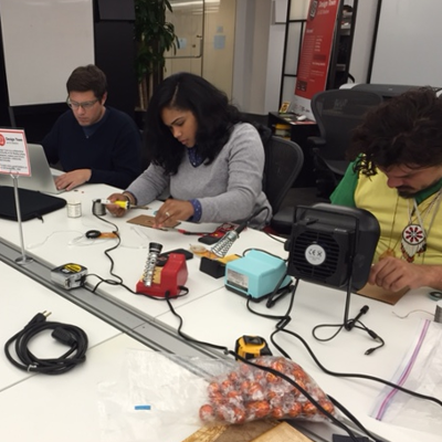
Wrestling with the MDX-20 at South End Technology Center
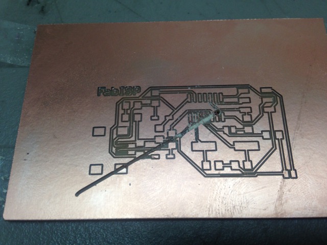
I continued to study with Beckett Dunning at South End Technology Center through this assignment. It was my first time dealing with any scale of CNC milling machine. We broke several end mills and ruined several boards of PCB. The machine would error out and mill in the air with what seemed to be random jogs. I ultimately narrowed the issue down to a software problem. There are flags that need to be adjusted in Fab Modules which get appended to the send command in Terminal. I got the machine to start “milling,” but my first ISP turned out to be an image of polished copper on FR-1. The homing of the Z became an issue. Trying to resolve that started me out on a path of adjusting the depth of the cut. On review of my board, Terence Fagan suggested that I was milling the FR-1 too deep. The goal is to simply remove the layer of copper foil and leave traces that can be tested with a multimeter. This is a similar process to cutting material on substrate covered in the vinyl cutter assignment. The problem to milling out the PCB ultimately was about leveling and fixturing.
While troubleshooting the MDX-20 at South End Technology Center, I met Ed Baafi who was in the lab to use the laser cutter. He asked me what I was doing. I had a stack of two FR-1 3” x 2” boards, one of which was sacrificial. I explained to him my process and progress. Ed took the two PCB’s off the Modela and then pointed out that I had layered double stick tape to the bottom. This was the cause of my leveling problems. When milling out the board, I had to account for an extra layer of tape which was roughly the thickness of what I was attempting to mill out. The result was a board that was milled too deeply in certain areas; yet not enough to not at all in other areas.
Setting up the SRM-20 across two labs
Roland stopped selling the Modela MDX-20 and we then started deploying monofab SRM-20. There is currently not a way to control the Z travel from FAB Modules. Usual workflow is to create an RML from Fab Modules and output the job through the VPanel. The interface is a bit like ShopBot’s control software. You can control the actuator along the X and Y with a D-Pad and the Z is control with Up and Down arrows. Cursor steps happen by default at 5mm. I can either home the X, Y, and Z at the lower left corner or in the center of the material.
When setting up the SRM-20 at Fab Lab Roxbury @ The Impact Studio, I came across two issues. First, the SRM-20 included a 3mm bit and a collet that fit. The included collet was too wide for the diameter of our Carbide Depot end mills. Specifically, I needed another collet to fit CU 129974 and CU 129985 which we use to mill out traces and boards. Roland has a 3.2mm collet (ZC-20-32) which can be ordered separately. The second issue was explained to me after a brief Skype call with Luciano Betoldi. The Z travel cannot currently be controlled by Fab Modules. Even if so, the physical Z does not go low enough to mill PCB that is mounted to the build plate. We resolved that a .75” wood block was needed as a sacrificial layer to successfully mill out boards.
My second encounter with the SRM-20 came about from the install of NOLA Fab Lab at Delgado Community College. Chris Carter of TIES set up the SRM-20 and most of the electronics workbench. Successfully testing the machine meant that we could mill out a board and have a consistent workflow to pass off to the new lab manager. We revisited the issue with using the .75” wood block for a sacrificial layer. Sallye Coyle of ShopBot Tools suggested we use wood pulled from the shipping crate of the ShopBot. We fixtured the wood block to the build plate with Intertape carpet tape. Around the time of our first tests, I needed to make my weekly Fab Academy Skype call to Wendy Neale and Craig Hobern at Fab Lab Wgtn. They explained to me that carpet tape… just wasn’t a go. Several issues arise when using carpet tape to fixture a wood block to the SRM-20’s build plate. Environmentally, New Orleans, Louisiana is hot and humid. Chris and I did observe that, over time, the tackiness of the tape wore off. Secondly, the build plate is smoother than what could effectively hold the tape and wood block combo. Even when the new manager, Sam Provenza, suggested MDF in lieu of the wood block; we came across the problem of heat and humidity. Wood likes moisture and will expand. I did find a surfacing routine in the SRM Player. We used the included 3mm end mill which had to registered to SRM Player and we homed the bit in the center of the wood block. It seemed to work on the first day. The second day, however, the same leveling problems happened that took me back to my days of wrestling the MDX-20 at the Tech Center. We left the machine with several options for sacrificial layers and fixturing. A call back to Fab Wgtn gave me the suggestion to use Corian solid surface material. Sallye suggested hard fixturing the sacrificial layer with screws using holes that are on the front and back of the build plate.
Good things come to those who don’t worry about the Big Picture
My biggest roadblock to completing this assignment was not lack of network members, instructors, or gurus. It was not old or malfunctioning machines. Despite all my issues, I still maintained that a poor workman blames the tools. My biggest roadblock was in my head. I could not wrap my mind around why I was dipping into the electronics inventory and soldering random components to random pads in between seemingly arbitrary traces. Where was the math?
I watched electrical engineering courses from MIT OSW. I perused books on building video game consoles. Still nothing was telling me why I would set the capacitors and resistors in between pins on a microcontroller and a source of power or pin outs to other boards. Because I couldn’t mathematically describe what I was doing, I didn’t want to do it. It’s tough, but the actual first step to learning was doing, and it took Wendy Neale to explain how courses in Fab Academy set milestones. So, I’m hoping I can describe what I’m doing; not now, but later.
I did manage to mill out an ISP board and solder SMD components on to it, last year. The next step was one that I happened to miss. You need a preprogrammed FAB ISP or the AVR ISP included in the Fab Inventory. Workflow for programming the FAB ISP starts when the RESET is active. When the RESET is active, the ISP will communicate on three dedicated SPI (Serial Peripheral Interface) wires. These wires are: MISO (Master In, Slave Out), MOSI (Master Out, Slave In), and SCK (Serial Clock). The SCK is generated by the ISP. It’s better to have an ISP around that is confirmed to work before attempting to program the FAB ISP. Wendy said, it’s pretty difficult to troubleshoot an ISP that is broken.
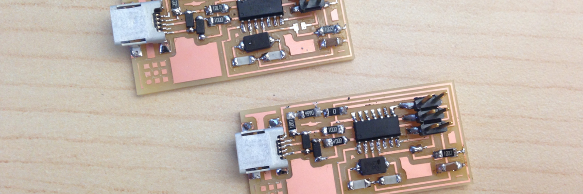
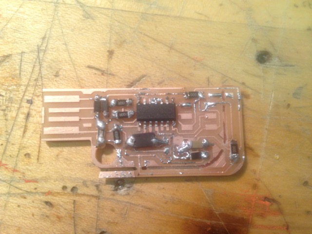
At FAB@CIC, I sat down with Luciano and Andrea Lane to mill out and solder the FAB ISP. Luciano and Andrea were both preparing electronics workshops for the week, and I thought it best to co-opt their experience. The first couple of iterations for me turned out poorly. The USB connections were off the traces on my first board. We did not have a heat gun at FAB@CIC. So, we attempted to desolder with the iron. Some of the traces were removed during that process. Luciano attempted to guide me through a fix by using a piece of copper braid to make the connection. After a couple of attempts, we resolved to remake the board. My second attempt was somewhat successful. All the connections were correct. In fact, we were able to get a green light from the AVRISP mkII indicating that the board was functioning properly. This turned out to be a fluke as we weren’t able to get a green light upon reconnecting the board to the programmer whether or not we used a different computer. Upon closer inspection, Luciano found that my components were a bit burned. His tip was to adjust my soldering technique. I tended to hover over spots while soldering. His tip was to find the hot end of the iron, lay on the pad for a second, then push a good glob of solder to make the joint. Once the solder melted, Luciano lifted the iron and blew to cool the joint. It was a quicker process that required less precision than I expected. We also used a piece of cardboard stuck to the table and mounted the board to the cardboard with double stick tape.
My third iteration got a green light from the AVRISP mkII. Mama Rosie was prepared to program following Anna Kaziunas France’s instructions. I set the paths so that Terminal would be able to find avrdude. I then downloaded and installed CrossPack AVR. I downloaded and installed XCode so that I could run make. I then downloaded and unzipped the firmware to my Desktop. I connected both the AVRISP mkII and the FAB ISP to Mama Rosie through her front USB ports. Connecting FAB ISP to the AVRISP mkII through the six pin connector got a green led indication. The FAB ISP was properly powered and connected. In Terminal, I changed the directory to the firmware directory and ran: “make clean”, “make hex”, “make fuse”, and “make program”. I got no errors. When I refreshed the USB profile in System Information, I saw “FABISP” as a new device. I was excited and ran to Luciano to tell him of my success. “Now,” said Luciano, “desolder the jumpers, get an Arduino, and program that to be sure that your board works.”
I had to download the Arduino IDE to Mama Rosie. While that was happening, I ran back down to FAB@CIC to desolder the jumpers. I left the 0 ohm resistor, though. When I returned with my FAB ISP and an Arduino UNO, I opened the Arduino IDE. Under Tools, I set the Board to “Arduino/Genuino UNO”. I also set the Programmer to “USBtinyISP”. I opened the Blink example and selected “Upload using Programmer” from the Sketch menu. I was able to send the program to the Arduino. I made a second attempt by adjusting the variables in the code to modify the blink. That worked as well. I was pretty satisfied with my board. Though I returned to FAB@CIC to remake one more after a weekend. This time, I was able to solder the board and program within 30 minutes. So, I was comfortable enough with the workflow to continue with my other Academy projects.
