Computer-Controlled Machining
The assigment page
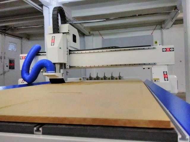
The goal of this week was to model and cut with a big CNC milling machine something big!.
⇝ 3D modelling in Fusion ⇝ CAM ⇝ Milling
For this part, I followed this tutorial and received a lot of advices from Luc.
Nesting
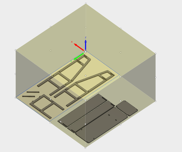
Before going in the CAM module, a good pratice is to make a new sketch where you do a square with the sheet's dimensions (here 1220x2440mm).
It's useful for doing your nesting.
Duplicate all your bodies, hide one the copy and use Align command in Modify tab to flat all your bodies (this way you have 2 design, 1 flat 1 assemble).
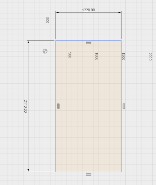
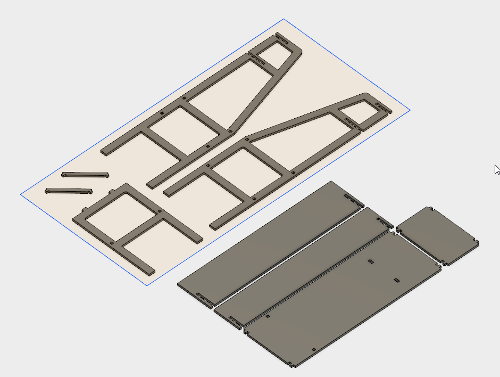
So now you're sure that your model will fit in the sheet.
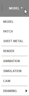
After modeling, you have to prepare your design in order to be milled. Select CAM in the menu:
Setup
Click on Setup:
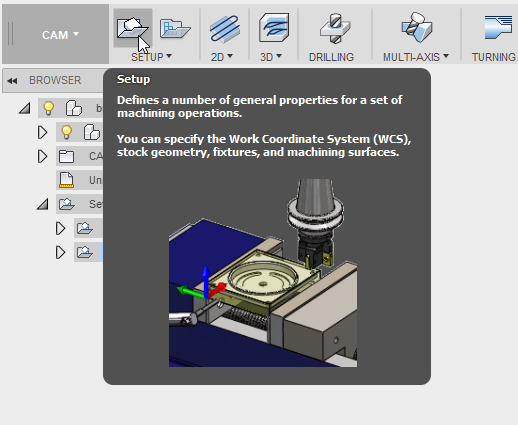
Setup menu is used for defining general properties like stock box, XYZ coordinates etc.
In your screen, it's suppose to be like this, a big yellow box surrounding your model.
First thing to do is to setup the Work Coordinates System (WCS), basically how are your X, Y and Z axis on your machines. In the dedicated menu in the Setup box, you can change the WCS:
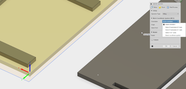
On Imal's CNC, the axis are like this:

Select one of arrow to flip axis.
After that, select parts of your design you want to mill in the model menu:
You see that the yellow box fits your design.
Last thing here, defining the stock point, where your origin will be on the machine. Select one of box's extremities. You have 3 points, one on the top, one in the middle and one the bottom.
If you choose in the top, you'll define machine's zero on the top of the sheet. If you choose in the bottom, you'll define machine's zero on the sacrificial layer.
>
Now click on the Stock tab. By default it's like this:
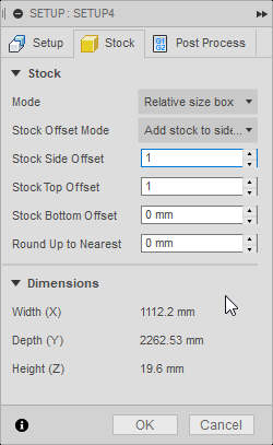
Our material here is a 18.6mm MDF. But here the height is 19.6mm because Stock Top Offset is set on 1mm. You can set it on 0. Stock Side Offset can be edited if you're design is near the sheet's sides:
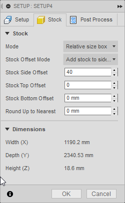
Now the yellow stock box is wider.
Last tab, Post Process. You can set a name for you're future file in Program Name/Number. Don't use special character and use max 8 characters or the CNC will not recognize it. Don't touch the rest.
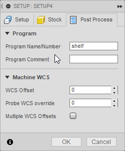
Click on Ok, your setup is complete.
Creating 2D contour toolpath
Click on 2D in the toolbar and select 2d Contour:
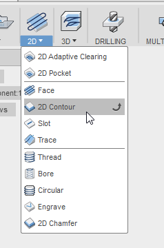
This window will appear:
Click on Select in the tool tab for setting your tool. This window will appear:
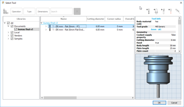
Here you can manage your tools, create new one and edit it. Click on this button to create a new end mill:

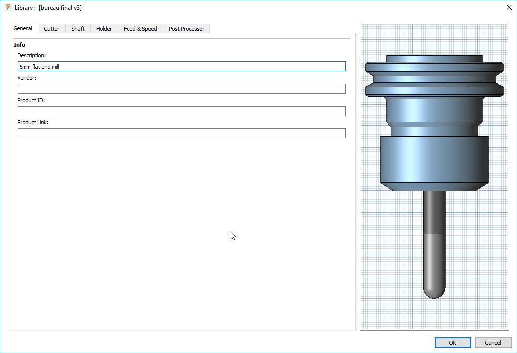
This window appear, on General tab. You can name your end mill (write the end mill diameter i.e):
Next tab, Cutter is important. You have to set your end mill according to the one you have. Use a caliper to mesure it.
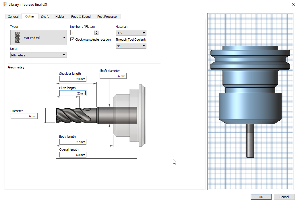
Those settings are for tool number 1 on the CNC, a 6mm endmill:
Flat end mill, 2 flutes, HSS, Clockwise, no coolant, Millimeters.
-Diameter: 6mm
-Shoulder lenght: 20mm
-Flute lenght: 20mm
-Body lenght: 27mm
-Overall lenght: 60mm
-Shaft diameter: 6mm
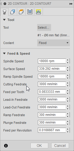
You can skip for now shaft and Holder and go to Feed & Speed tab. It's where you decide milling speed:
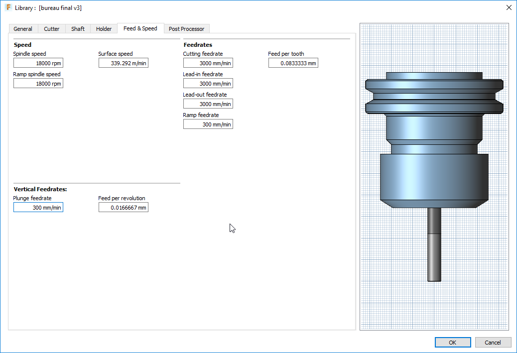
-Spindle speed: 18000 rpm
-Ramp spindle speed: 18000 rpm
-Surface speed: 339.292 m/min
-Cutting feedrate: 3000 mm/min
-Lead-in feedrate: 3000 mm/min
-Lead-out feedrate: 3000 mm/min
-Ramp feedrate: 300 mm/min
-Feed per tooth: automaticly set
-Plunge feedrate: 300 mm/min
-Feed per revolution: automaticly set
Last tab, Post Processor. Here we will use the first tool, so set Number to 1. Don't touch the rest. Check if Manual tool change is uncheck, this machine has a tool changer.
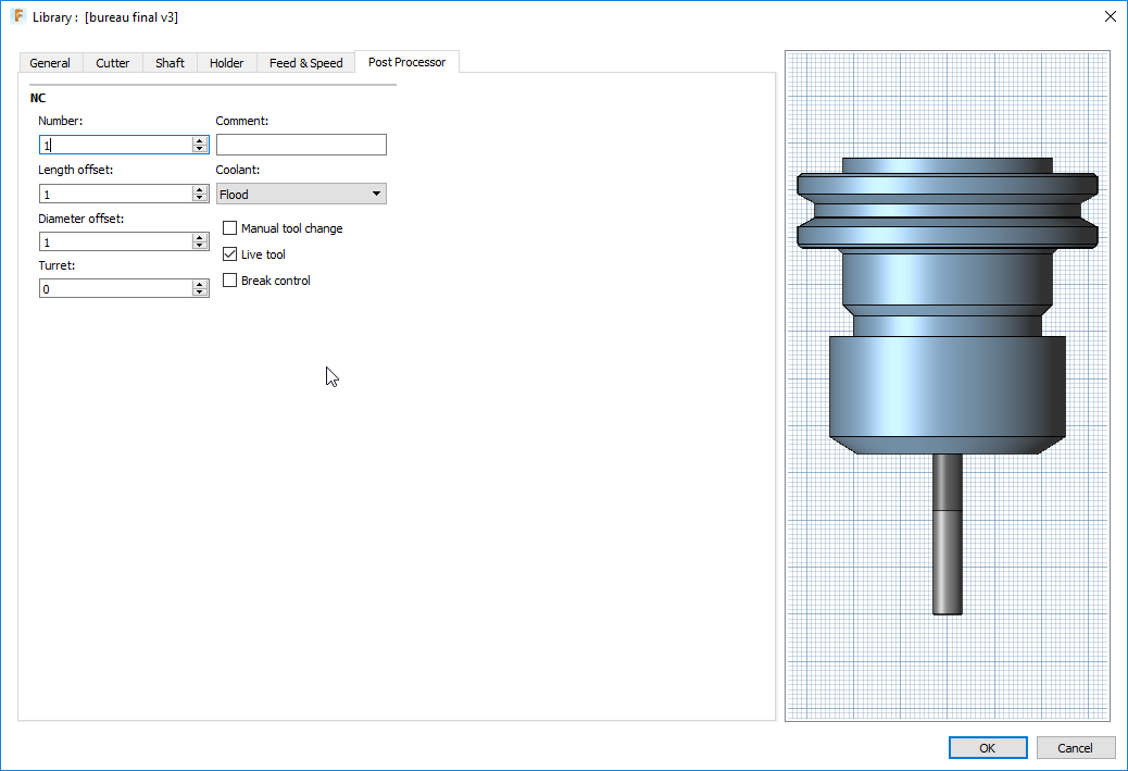
You can click OK. In this menu you can change speeds manually:
Go to the Geometry tab. You have to select the contours you want to mill. With the View Cube, go to Bottom view (you have to select bottom contours, it will be easier) and select insides path. We'll do an another setting for outsides contours:
Selected contours appears in blue. The other options are for exemple if you want tabs etc.
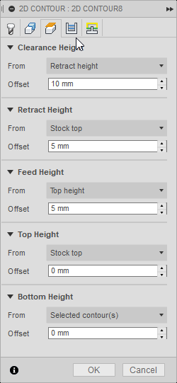
Go to the Heights tab. You can edit some heights here, like Retract Height if the endmill touch your material when it moves to another point.
In Passes tab touch to nothing but Multiple Depths. In maximum Roughing, write 6mm because 18/6=3. It will do 3 passes. Set this value as you want. 3 passes is a good start.
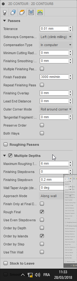
For this example, Linking tab is not necessary. Click OK.
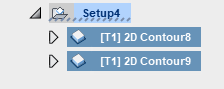
You've just finished your first toolpath! Now select your toolpath and click on the simulation button. Click on Play (>) to start simulate and check of there's no problems.
Now you can edit a second 2d contour toolpath for outsides contours. We're making like this to be sure that the insides contours are cut before the outsides. If you started with outsides contours, you just have to move the tab under insides. When it's done, select your 2 toolpath, simulate and click on Post Process button:

This menu allows you generate and save the Gcode who will be use by the machine.
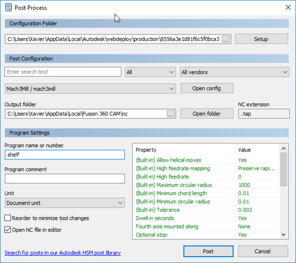
The most important thing to change is the Post Configuration config. Select Mach3mill/mach3mill. Name your file and click Post.
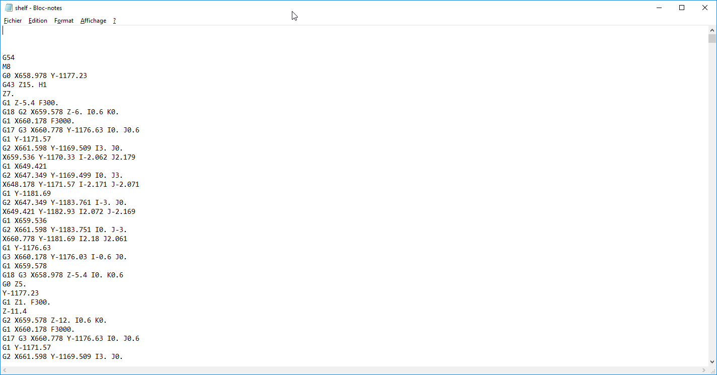
Your Gcode is generated but you have to change some lines manually. Open your .tap with a text editor:
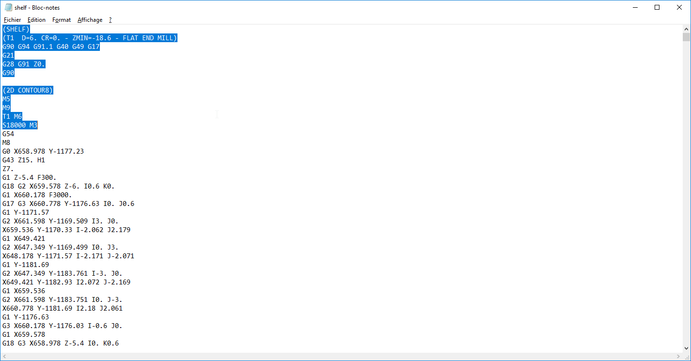
Delete all the line before "G54"
And copy-paste this header:
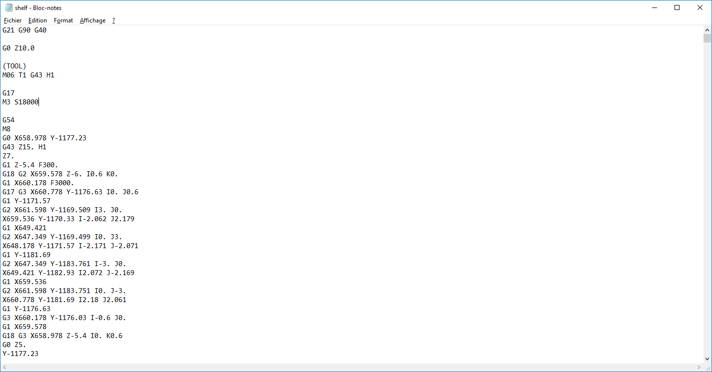
G21 G90 G40
Save it, copy it in an USB drive and you're ready to mill.
G0 Z10.0
(You're using Tool 1 so T1 and H1. For tool 2 H2 etc.)
M06 T1 G43 H1
G17
(S18000 stands for the speed. If you set it lower or higher don't forget to change it here)
M3 S18000