networking and communications
.
lecture / slide: Fabacademy 2015 04.29D Lesson13: Networking and Communications MIT CBA Networking and Communications.
topics: purposes, serial, OSI layers, physical media, modulation, channel sharing, errors, networking, RF.
assignment: design and build a wired &/or wireless network connecting at least two processors!.
experimentation: I decided to go for the serial bus setup that Neil suggested us and followed mainly the tutorial by the guys from Fab Lab AS220 in Providence. I downloaded the files from the MIT CBA class page and started milling a bridge board and three nodes on the Roland MX-20 and stuffed them as usual. Actually the bridge board is also a node but holds a FTDI connection in order to communicate to the computer. The communication between the nodes then works via serial Tx / Rx protocol.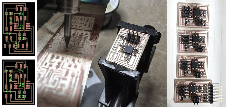 Well. once everything was soldered I had a look at the cables. I was using the 3x2 header but only connecting with four cables (Tx, Rx, Vcc, Gnd) that will be the serial communication between the nodes. Just get a good distance between each header and keep the position in mind. I downloaded also the c and make file from the MIT CBA page and/or the AS220, they should both work fine. Then my workflow was the following one: I made per Node an own folder, opened the c file and changed in Line 41 the node iD to 0, 1, 2 and 3 and saving the file. Going to terminal I was running the following commands and connected the FabISP to each corresponding board that I was flashing via make file in terminal from the proper folder, that's it!
Again, it's important to change the node id inside the c file:
Well. once everything was soldered I had a look at the cables. I was using the 3x2 header but only connecting with four cables (Tx, Rx, Vcc, Gnd) that will be the serial communication between the nodes. Just get a good distance between each header and keep the position in mind. I downloaded also the c and make file from the MIT CBA page and/or the AS220, they should both work fine. Then my workflow was the following one: I made per Node an own folder, opened the c file and changed in Line 41 the node iD to 0, 1, 2 and 3 and saving the file. Going to terminal I was running the following commands and connected the FabISP to each corresponding board that I was flashing via make file in terminal from the proper folder, that's it!
Again, it's important to change the node id inside the c file:
#define node_id '0'Open Terminal, connect the bridge board (node 0) with the FTDI cable via 6 pin header to the FabISP and back to your computer, and run the following command after you have gone to the folder location of Bridge (= Node 0):
sudo make -f hello.bus.45.make program-usbtinyIn case you are using the AVRISP MK2 programmer run this one:
sudo make -f hello.bus.45.make program-avrisp2You should see some line of codes and hopefully the LED on the board blinking! Connect the other boards and navigate to the corresponding folders of the nodes. The .make file will call the .c file and generate both .hex and .out file. Once all boards were flashed, you can remove the FabISP and communicate via FTDI cable only.
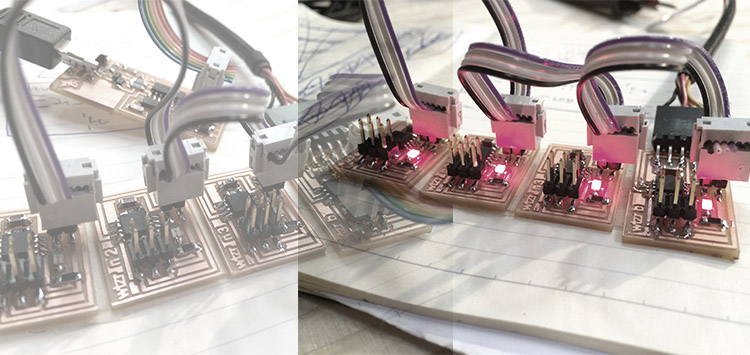 Then using the Arduino IDE we can monitor the serial nodes: just open Arduino, go to Tools, set Attiny45 as processor with 8MhZ internal clock (as seen in the make file) and open the serial monitor. Now you can type in your keyboard the number of the node (+ press enter) and all LED will light up plus the one you just chose additionally once. Of course this can be modified.
I was lucky to get some help from my friend and colleague Ronald and use his laptop since my USB ports on the MacBook are causing some weird problems at the moment. (to be solved)
Then using the Arduino IDE we can monitor the serial nodes: just open Arduino, go to Tools, set Attiny45 as processor with 8MhZ internal clock (as seen in the make file) and open the serial monitor. Now you can type in your keyboard the number of the node (+ press enter) and all LED will light up plus the one you just chose additionally once. Of course this can be modified.
I was lucky to get some help from my friend and colleague Ronald and use his laptop since my USB ports on the MacBook are causing some weird problems at the moment. (to be solved)
.
files: Files wlzr Fab Academy '15 // w14.
bookmarks / links: Fab Lab AS220 Tutorial on Networking - Hello Serial Bus Sparkfun Serial Communication Tutorial Arduino IDE.
global review: Fabacademy 2015 05.06B Review13: Networking and Communications-

Any content on these pages by Alexander Nikolas Walzeris licensed under a Creative Commons
Attribution-NonCommercial-ShareAlike 4.0 International License