output devices
.
lecture / slide: Fabacademy 2015 04.15D Lesson11: Output Devices MIT CBA Output Devices.
topics: electrical safety, power supplies, RGB LED, LED array, LCD, video, speaker, DC motor, servo, stepper motor, motor control, shape memory, piezo.
assignment: add an output device to a microcontroller board you've designed and program it to do something!.
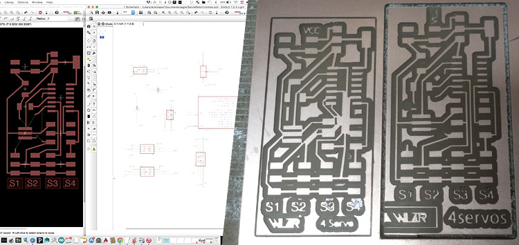
experimentation: Since my final project will have to deal with 3 or more servos I followed the servo template from Neil. I downloaded the c file, make file and images that would help me replicate/modify the template: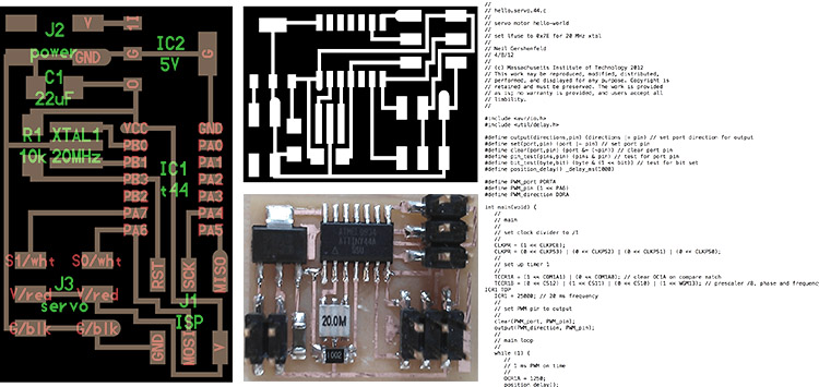 I added two more servo output ports that would allow me to connect 4 Servos in total. As we learned earlier I ran the process of designing in Eagle Software and producing the PCB with the Roland MX-20 milling machine. Since I didn't verify the Design Rules (DRC) - in which you can check distances between milling traces - my traces were too close and I had to slightly adapt the design and remill:
 Also due to the fact that I added two additional outputs I had to use some cables to connect them. I will try to avoid this in the future since the soldering of cables is messy, not reliable and the whole board pretty vulnerable. I ended up resoldering the cables in the end because they were too weak. I wouldnt succeed using my FabISP and didnt find the problem, I just got an error in Apple Terminal when trying to program the board. Thanks to help of my tutors Ferdi and Santi I decided to use the AVRISP Mk2 to programme the board, just because it would light up green if the board is soldered and connected correctly, so to speak ready for programming. Of course it was not and I found a mistake in the schematic drawing in which I didn't connect the labels correctly. Also I decided to go for an external power supply that gives constant 5V, even though a 9V battery would do the job probably as well (the board needs to be powered externally also for programming):
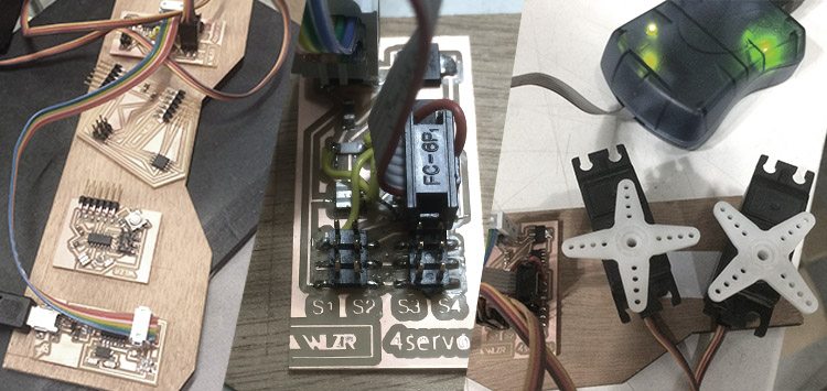 Now that the hardware was ready I tried to adapt the c file to run with four servos but I could not even make one run from the script. The workflow is as follows: connect and power the board, edit c code if desired, make sure the directory of c and make file is the same folder, the make file will also generate a hex file there. Open terminal, navigate in the folder, run this: "sudo make -f FILENAME.make program-*". Replace * with 1) usbtiny if using FabISP (then it is: .. program-usbtiny) or 2) avrisp (program-avrisp2). Either because I am new in c coding or maybe the solderwjob was done bad, I had no idea what's going on and after a lot of testing I decided to go for the solution using Arduino IPE to upload a code my colleague Milena shared on her homepage. It also needed some tweeking, checking many times for the correct folders and which pins are connected and understanding of PWM the servos would finally run:
.
files: Files wlzr Fab Academy '15 // w12.
bookmarks / links: Wikipedia Design Rule Checking Fab Academy Milena Orlandini Sparkfun Pulse-width Modulation (PWM).
global review: Fabacademy 2015 04.22B Review11: Output Devices-

Any content on these pages by Alexander Nikolas Walzeris licensed under a Creative Commons
Attribution-NonCommercial-ShareAlike 4.0 International License