input devices
.
lecture / slide: Fabacademy 2015 04.08D Lesson10: Input Devices MIT CBA Input Devices.
topics: inputs, switch, magnetic field, temperature, light, step response, acceleration, orientation, rotation, sound, distance motion, vibration, force, loading, image.
assignment: measure something: add a sensor to a microcontroller board that you've designed and read it.
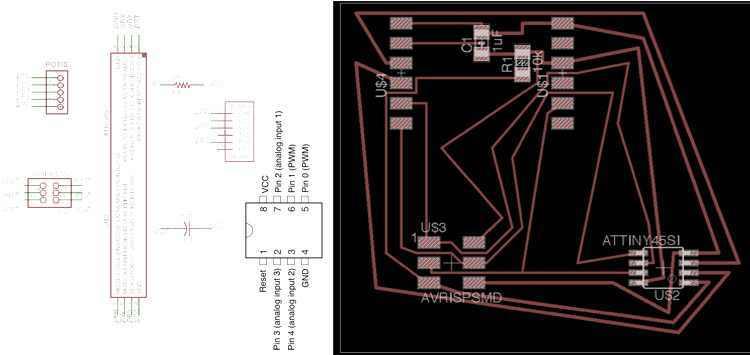
experimentation: For this week's assignment I was thinking of using a joystick as an input device and built up a board according to this. The joystick I got is basically the one inside a PlayStation 2 controller with the name KY-023. A joystick itsellf consists of two potentiometers and in this case also a switch that enables movement in the z direction. As a template I was looking to Neil’s template for the switch board based on a ATtiny45.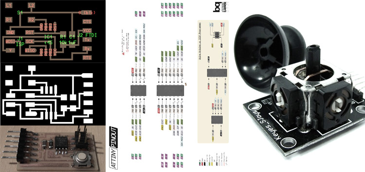 As I tried to understand the way Neil organises his board I was eager to integrate the joystick into it. After some productive feedback from Ferdi I used a 6pin header instead of the switch and checked the pins P0:P5. It is also important to understand that a potentiometer will give us analog data, ranging from 0 to 5V, using 2.5V in the resting position. Tilting left/right or up/down will vary these voltages and the board will slice the values into 1024 steps before transmitting to the computer. The switch indeed is giving us a digital input, making only 0 or 1 values. Once again we worked in Eagle software. I had some issues with the libraries but I downloaded/activated fab and Neil’s library (01_ng). Again checkin for components, labelling, renaming, etc. and going to the wiring process. I understood that I will connect both X and Y values from the potentiometers in the joystick to pins PB3 and PB4 as they accept both analog and digital data. The Switch of the joystick needs to connect to PB1 that supports also digital data (PWM). Pins need to be labelled with the same name in order to then ask for connection in the board layout window. This time I was looking for a more fancy shape and I finally tested the auto routing that worked pretty well, of course I manipulated manually afterwards but the circuit was valid. Make sure to check before the DRC (Design Rule Check; 16mil instead of 8mil!). I used a 6pin header for my joystick, having one free coming from PB0 (PWM) that will be used in the future for some output! Check in the layers to only show the Top Layer then go to export -> image PNG, monochrom and try to get around 1500x1500 pixel for the file, the DPI will be between 300 and 1000. Save it
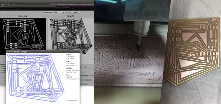
 Using the Roland MX-20 milling machine from our Green Fab Lab Valldaura I was able to set up all the necessary steps and mill within 20 minutes the whole board inclusive a test run on its border edge and the proper cut along the edge at ther very end. The steps are the following:
Start the computer connected to the milling machine, run “sudo fab” in the terminal of Ubuntu, type password and let’s go. Set the import settings and go to the next step. Optimal is to test run the interior/frame file (white interior that has all the board inside, in the best case bigger than it of course; surrounded by black). All these images should be safe as indexed color png, watch out for the DPI (keep it the same!). Load the png, drive manually to the x,y minimum and set the z manually; set offset to 1 and z to 0 and click “Make path”. Next: make .rmd and start! A new window will pop up and you can begin milling. Be sure to set in the top middle the right tool! I used 64 bits for this step, speed on the right was set to 8mm/s instead of 4. If all went nicely, load the other png of the schematic and change the offset to 4, z to -0.1 or -0.15 depends on how it ran and maybe increase or lower the speed. Click: “make path”, “make .rmd” and run it! Again, new window, press “begin” and watch it happen, it will run 4 rounds (the amount set in “offset”). Keep a finger on the “VIEW” button, just in case! This will pause but not stop your job. If all was good we are ready to change the millbit to 32th! press View, then both up and down buttons at the same time. Take the tool and open the part that holds the drillbit. Exchange it and close the screw again. Drive it back to the same x,y minimum as before and set the z manually again! Select in the top middle the tool (32th) and put offset 1, top z to -0.5 mm instead of -1.7mm; bot z to -1.5mm instead of 1.7mm. Press “make path”, “make rmd” and run itttttt. The piece willl be ready to take out. If not play with the z values to get a straight cut through the board.
Using the Roland MX-20 milling machine from our Green Fab Lab Valldaura I was able to set up all the necessary steps and mill within 20 minutes the whole board inclusive a test run on its border edge and the proper cut along the edge at ther very end. The steps are the following:
Start the computer connected to the milling machine, run “sudo fab” in the terminal of Ubuntu, type password and let’s go. Set the import settings and go to the next step. Optimal is to test run the interior/frame file (white interior that has all the board inside, in the best case bigger than it of course; surrounded by black). All these images should be safe as indexed color png, watch out for the DPI (keep it the same!). Load the png, drive manually to the x,y minimum and set the z manually; set offset to 1 and z to 0 and click “Make path”. Next: make .rmd and start! A new window will pop up and you can begin milling. Be sure to set in the top middle the right tool! I used 64 bits for this step, speed on the right was set to 8mm/s instead of 4. If all went nicely, load the other png of the schematic and change the offset to 4, z to -0.1 or -0.15 depends on how it ran and maybe increase or lower the speed. Click: “make path”, “make .rmd” and run it! Again, new window, press “begin” and watch it happen, it will run 4 rounds (the amount set in “offset”). Keep a finger on the “VIEW” button, just in case! This will pause but not stop your job. If all was good we are ready to change the millbit to 32th! press View, then both up and down buttons at the same time. Take the tool and open the part that holds the drillbit. Exchange it and close the screw again. Drive it back to the same x,y minimum as before and set the z manually again! Select in the top middle the tool (32th) and put offset 1, top z to -0.5 mm instead of -1.7mm; bot z to -1.5mm instead of 1.7mm. Press “make path”, “make rmd” and run itttttt. The piece willl be ready to take out. If not play with the z values to get a straight cut through the board.
 I collected all the pieces necessary to complete the button / switch board and soldered them on the board. Unfortunately my Logic Boards failed again and I had no laptop for some days. Nevertheless there is always a way to work, there is no excuse! I went into the datasheet of the ATtiny45, trying to understand the pin outs. Also Ferdi sent us an amazing reference to a site called pighixxx that lists the pinouts more nicely. With some sketches of my hooking up ideas I began to download the code on my iPad and compile it online! My board is somehow based on Neil's switch board but runs the c code of the phototransistor board (thx to Santi who helped me a lot!):
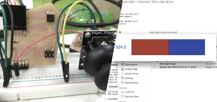
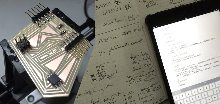 I was not sure about my circuit might work or not I chose a breadboard to have a prototype that is fast to change and or now I am using one potentiometer of the joystick. Making sure to get the pins and especially the VCC and GND right I compiled the c code via "make file" procedure in the terminal of Santi's laptop using the FabISP programmer from earlier. I uploaded the python code and disconnected the FabISP, communication from the laptop to the board directly via FTDI. The x axis of the joystick is now sending his position over to the laptop that displays the values (0 to 1023; around 512 to be in the middle):
 Here a small video using one axis of the joystick and visualising via Python:
.
files: Files wlzr Fab Academy '15 // w11.
bookmarks / links: Atmel ATtiny 25/45/85 Datasheet PighiXXX electronics and programming Sketchpad co-creative coding C Programming Python Programming.
global review: Fabacademy 2015 04.15B Review10: Input Devices-

Any content on these pages by Alexander Nikolas Walzeris licensed under a Creative Commons
Attribution-NonCommercial-ShareAlike 4.0 International License