3D Scanning and Printing
To complete given task for this week ; I selected one object for scanning ;edited this object inside design software and printed it in following flow.3D Scanning:
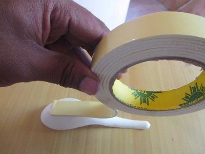
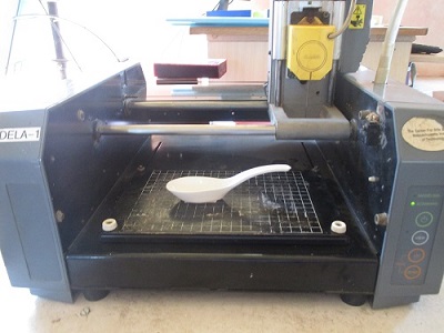
Scanning object : Fiber Spoon
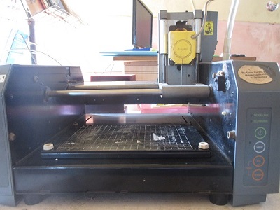
Target machine :Modella MDX-20
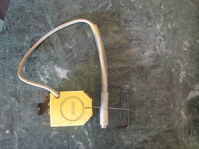
Step 1: Replaced modella milling head with Scanner as shown in fig.
 |
 |
Step 2: Paste scanning object in middle on Modella bed with double sided tape.
 |
 |
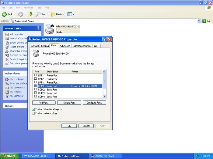
Step 3: For scanning I used here Dr. Picza software ; downloaded and installed on Machine. Step 4: To communicate with Modella MDX-20 Machine done first port settings. For this Click START -->Printer & faxes --> Right click on Roland Modela MDX-20 printer --> click on Properties -->click on Port tab --> select the port --> click on apply and ok .
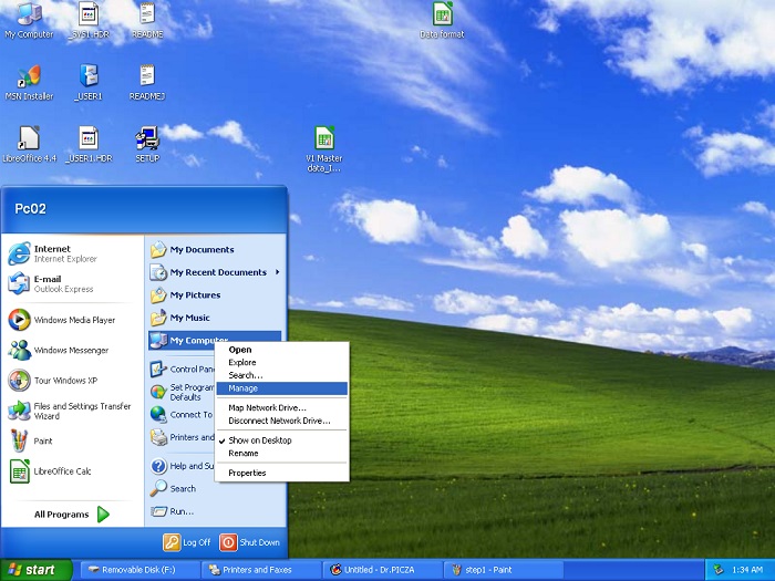
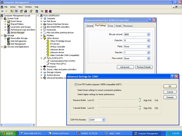
Step 5: Now Right click on My computer--> Click Manage--> Inside Manage window click on Device manager--> select Communication Port.--> Double click on Communication port--> Do settings as shown in fig.
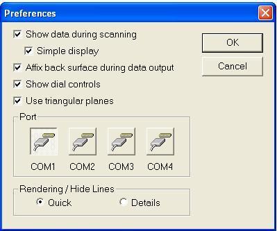
Step 6: Now open Dr.Picza software window go inside File--> then Preferences --> Do setting as Shown in following --> select COM1 --> Click OK
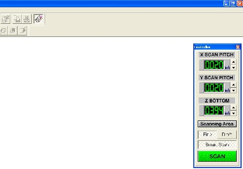
Set X scan pitch=0.020 inch ;Y scan pitch= 0.020 inch; Z bottom =0.394 inch.
 |
 |
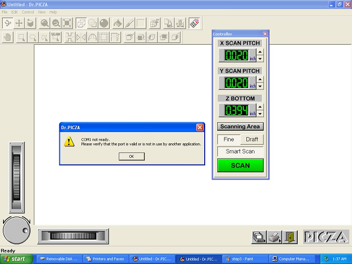
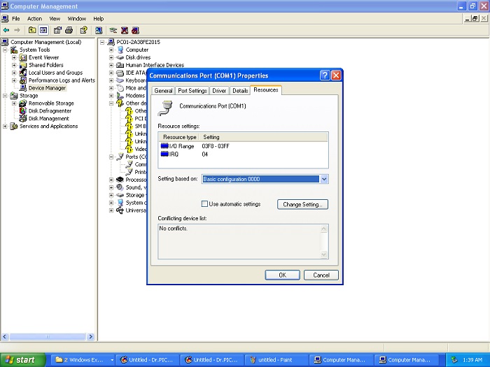
Step 8: After clicking on Scanning area I got a error Message COM1 port is not ready.To resolve this Go to My computer--> Manage--> Device Manager--> Double click on Communication Port--> Resourses-->Unclick default automatic setting and select basic configuration 0000.
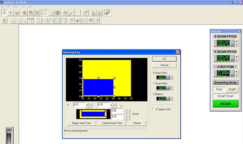
Step 9: Selected scanning area as per measurements of scanning object(Spoon)placed on bed.Done scanning area check with Begin area test button .
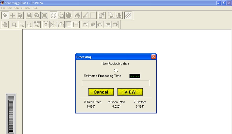
Step 10: After area testing click on 'Fine' and 'Smart Scan' button and start scan with clicking on 'Scan' button.Following window appeared on screen.
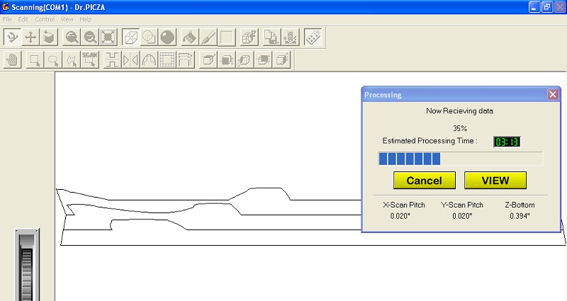
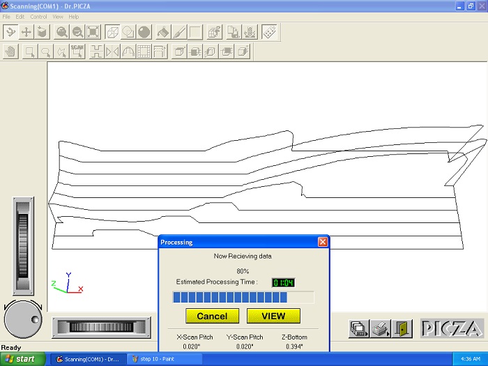
Step 11: Scanning is in progress.
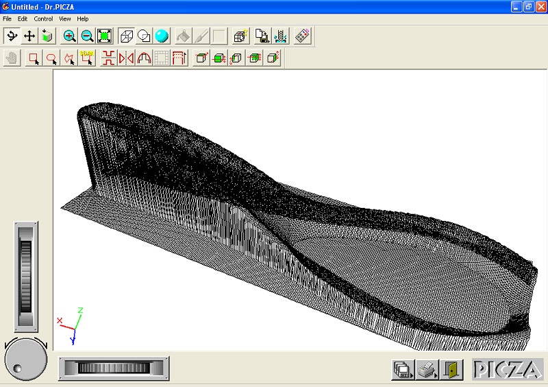
Final Scanned Object..
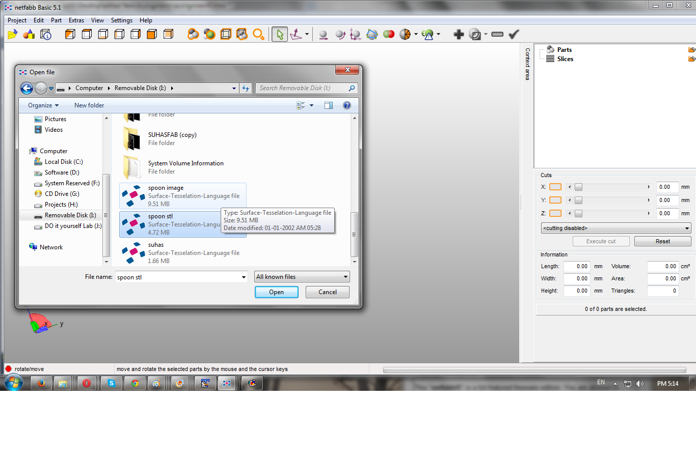
Step 12: Now go to File -->Export-->STL format--> Save to destination address.
Object Editing and 3D printing: To make scanned object file ; 3d printable I edited this file inside Netfab design software .Its available here for easy download.
Step 13: Open Netfab Window and import scanned object .stl file from destination.
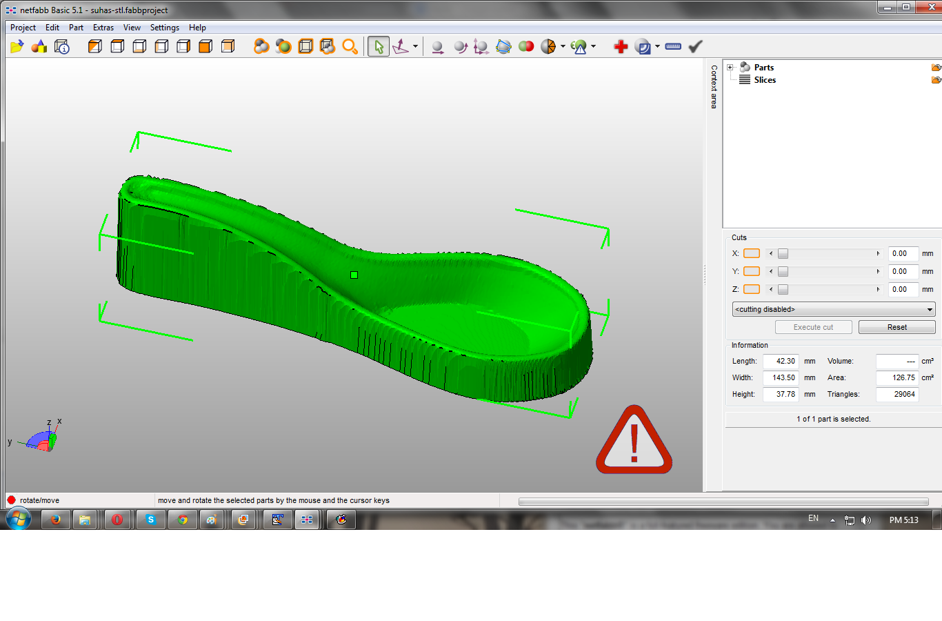
Step 14:Now click on '+'button to get net view.
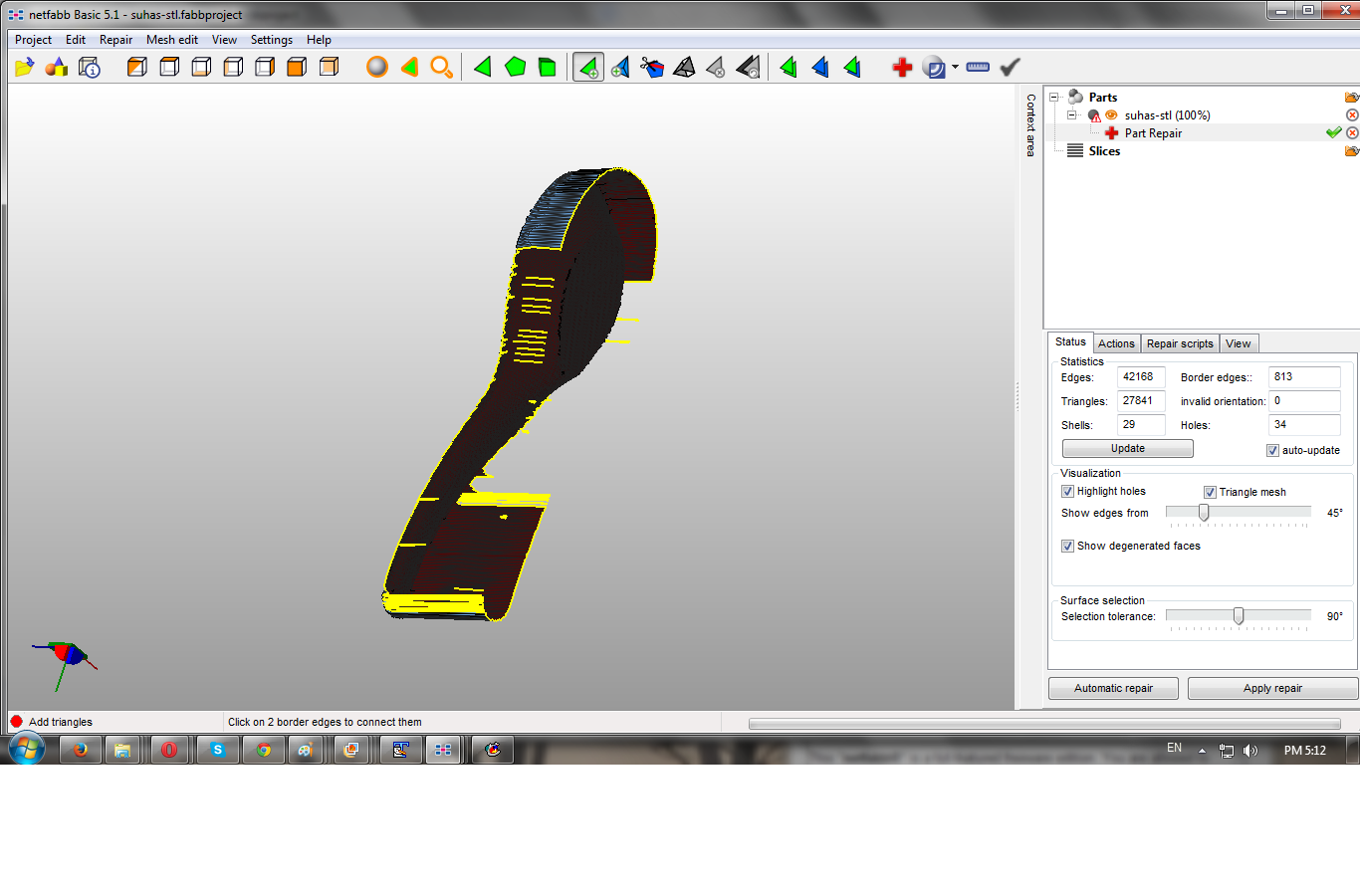
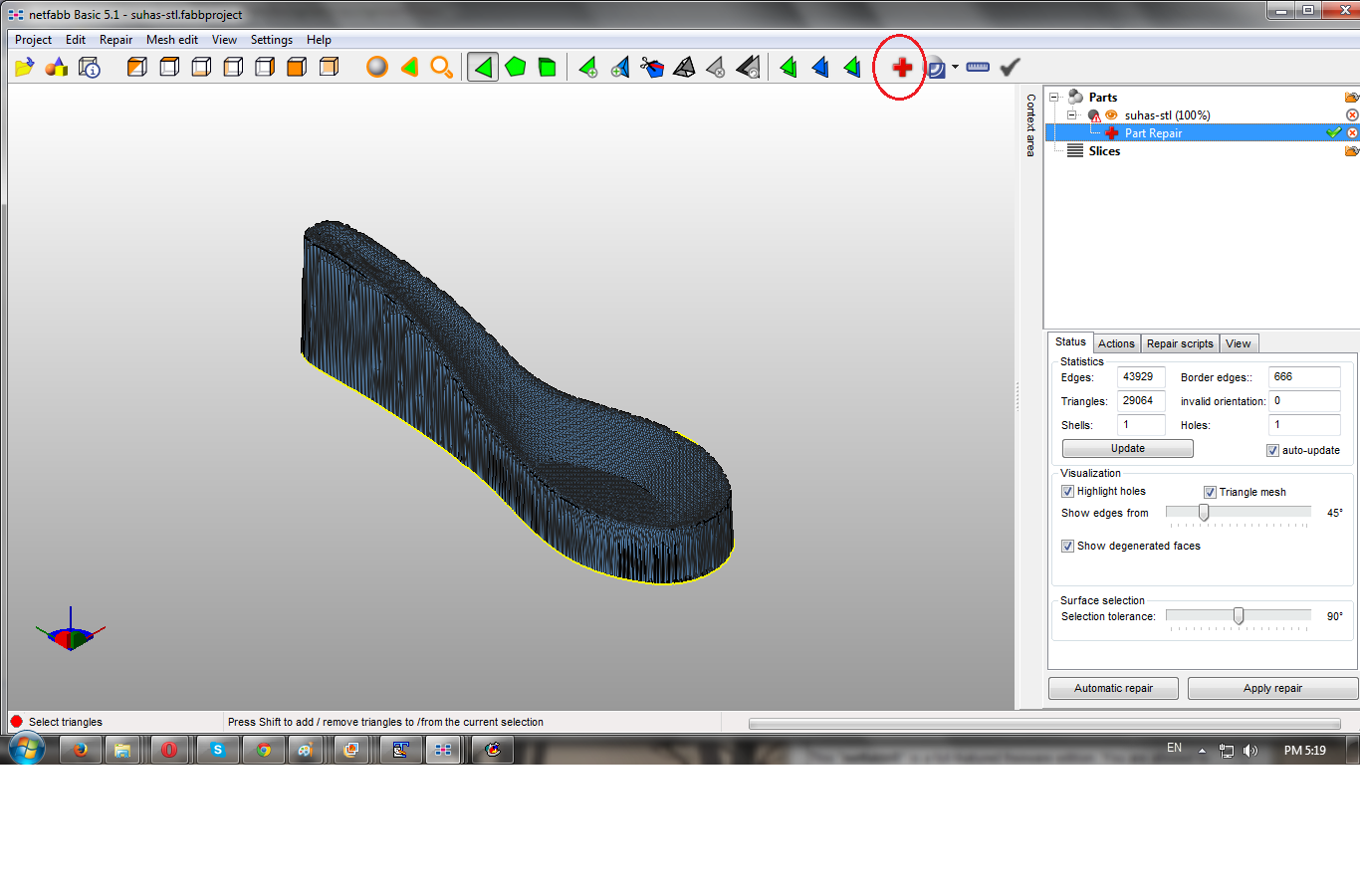 Step 15: Removed unwanted part of object with selecting trainguler remove tool . Press ctrl and select unwanted Traingles and then click on this tool as shown in fig.
 Step 16: After this apply automatic repair we get final printable object .stl file as shown below. Save this file.
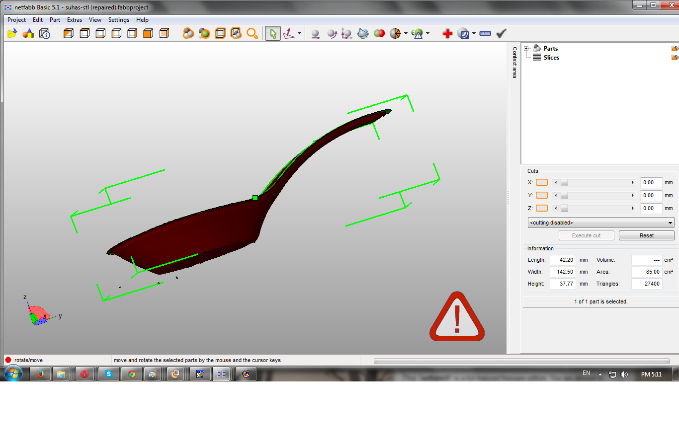 Step 17 : Import .stl edited file inside 3D printer supportive software.Here we are using Riprap based Cura and Printrun softwares for 3d printing.
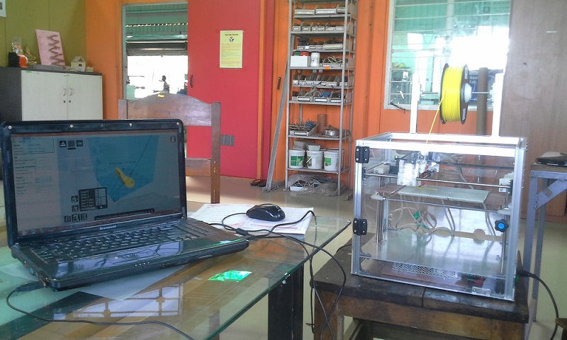
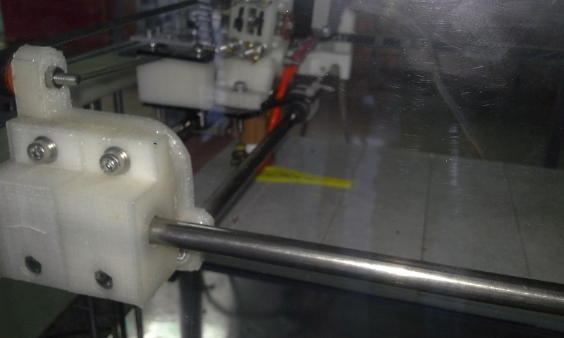
Step 18: Printing is in progress ..
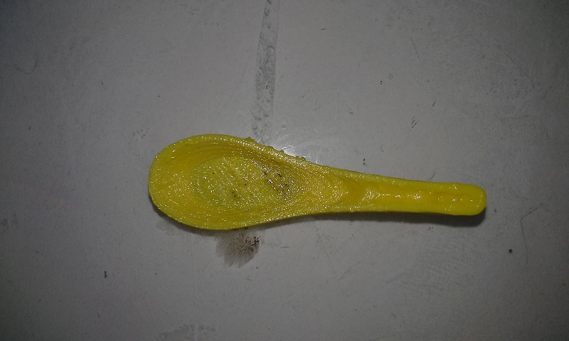
Final 3d printed object..
Download all files from here:
3D scanning and Printing.zip
3D design and printing :
For 3d design I used blender 3D design software to design rupee symbol mold.
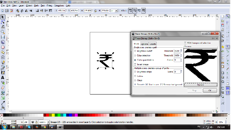
Step 1: Download And import .png file of Indian Rupee symbol inside Inkscape. Set dimensions ;as for 3D printing its needs to trace all nodes of an object. For this go inside'path' window; select 'Trace bitmap'; following window will pop-up set colour quantisation and export as .svg file .
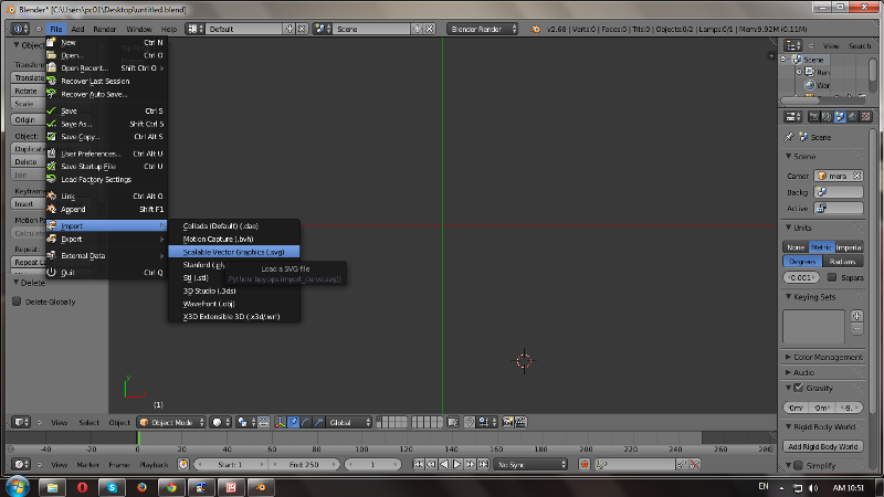
Step 2: To make this Rupee symbol 3d printable; imported this .svg file inside Blender 3D design software. Blender is rich with toolset and open source. Followed video tutorial of blender for this Mold design.
Step 3: Inside blender Import-->Scalable vector graphics(.svg)file from destination as shown below.
Step 4: Now go inside View--> select top view ; Here select first scale for design to make it 3D printable( selection of scale is more important as I get stucked here ;Amitraj took me up!! During export; design dimensions gets multiplied with scale and design becomes unexpected) To select scale; at right hand side of window go inside Scene-->Metric-->Scale-->here scale is 0.001m (by default its in meter).
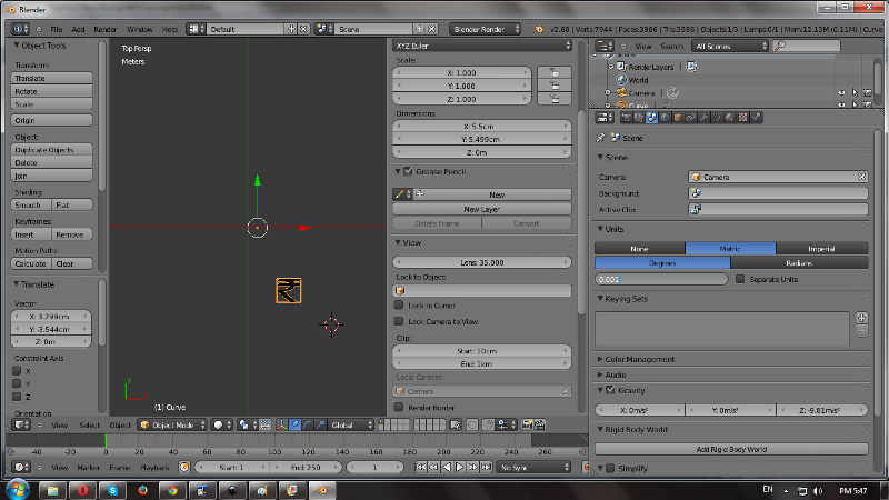
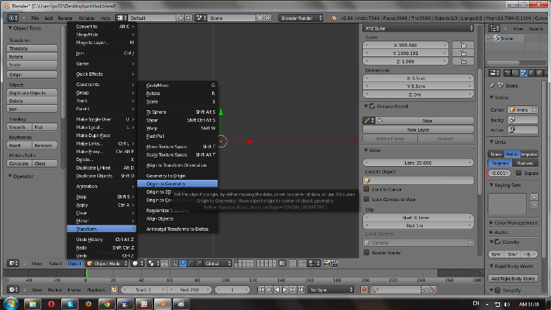
Step 5: Check dimensions of an object;set it as per scale. For rupee sybmbol I set it 55mm X 55mm .Take object at center with Object --> Transform--> origin to geometry; and keeping location co-ordinates all '0'.
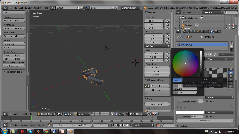
Step 6: 2D rupee symbol extruded 10mm with Z axis ; for extrude select object and go inside Curve-->Geometry--> Extrude(here object extruded with 10mm).Change object color under SVGMat --> Diffuse and slide cursor.
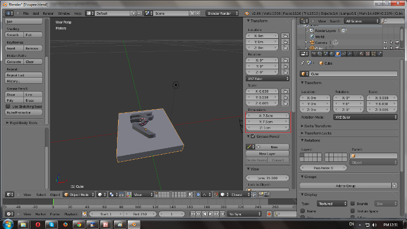
Step 7: To convert this symbol in Mold its need to cover with box outside. Go inside Add--> select Cube -->Set dimensions as 75mm x 75mm x 10mm. Now make origin to geometry for this object and set location axes at '0'.
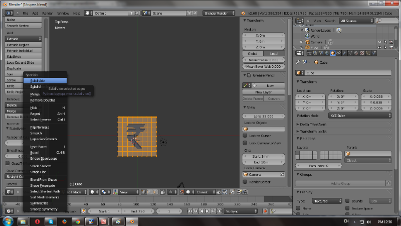
Step 8: To keep borders for an mold object;have to extrude cube sides with width 10mm and hight 10mm distance. For this Go inside Top view--> select Edit mode--> Press 'W' for subdivide a base--> Make number of cuts '7'(as total width is 75mm).
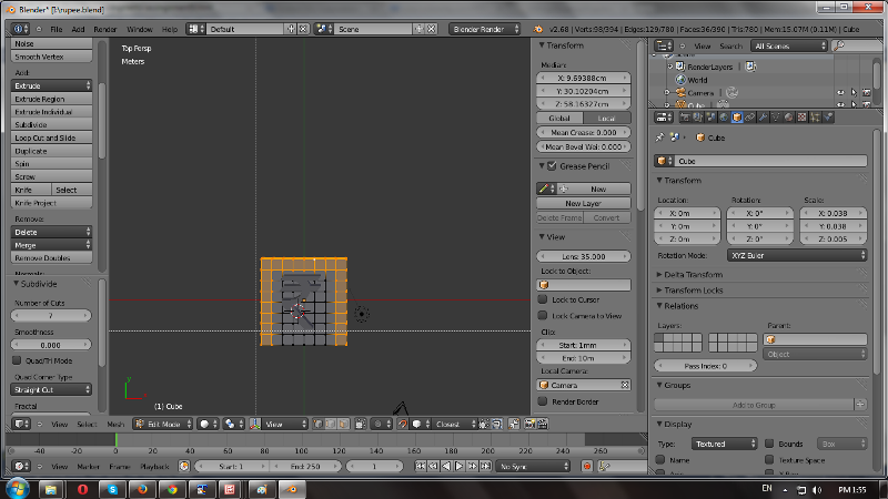
Step 9:Select edges with pressing 'B' for border; select and extrude these under extrude region tag placed at left side of window along z axis 20mm.
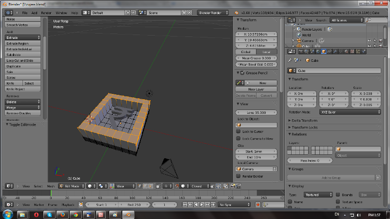
Step 10: Now select Object mode ;here we require whole object in group so select both with shift key and apply ctrl+J for joining meshesh to each other. Select scale with ctrl +A--> scale as '1'and export image in .stl file format and save it.
Step 11: Now to check design is 3D printaeble or not ; open it with Netfab. For this design it gives error message 'incorrect mesh'as there are Nonmanifold edges are present in design.
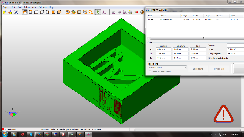
Step 12 : To correct and make design printable ;need to repair it. For this click on '+' sign-->select Autorepair -->Execute--> apply repair--> Remove old part.After this error massage goes and mesh becomes valid.
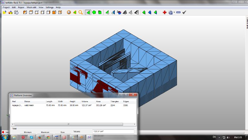
Step 13: Right click on design; select save as STL .
Imported this .stl design file in 3D printing software for Up plus2 3D printer.
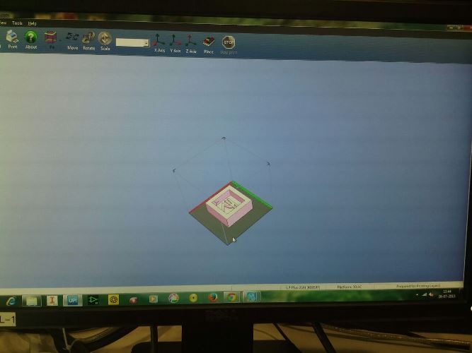
Selected printer as Up plus 2 printer for solid fill and material ABS.
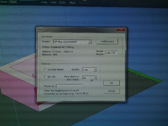
Scanned printing area with place and given print.
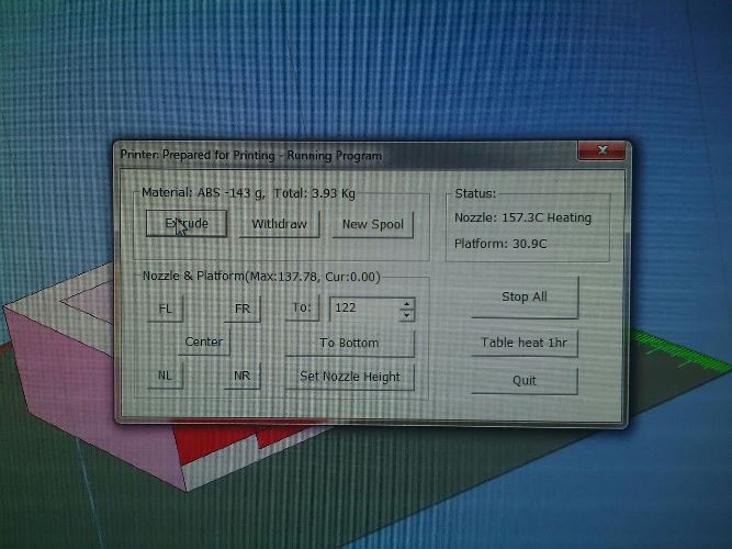
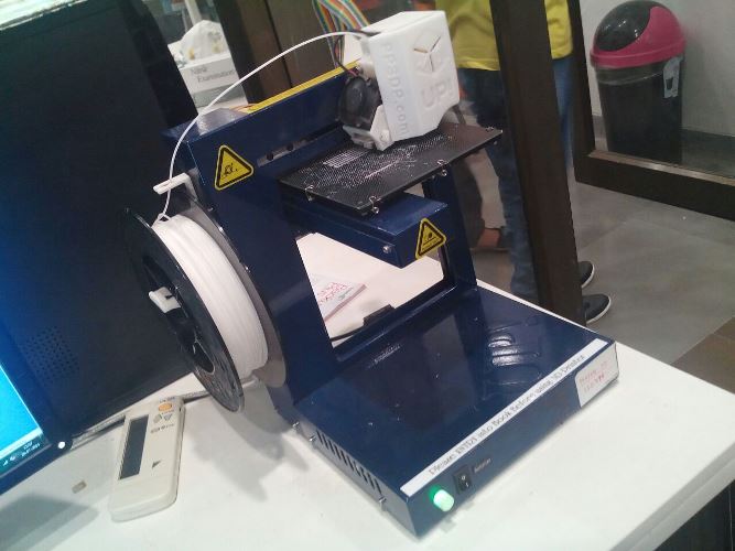
Printing is in progress....
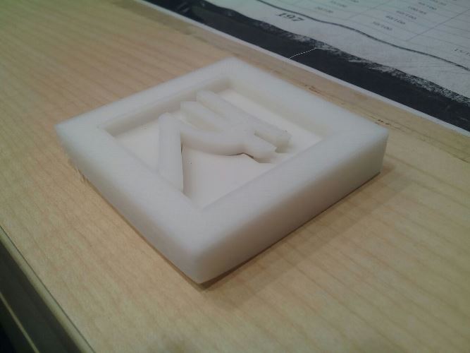
Final printed object..
Download all files from here:
Mold design file