Something more fun. Something with more Fab Lab skills. Something called: MagMaze
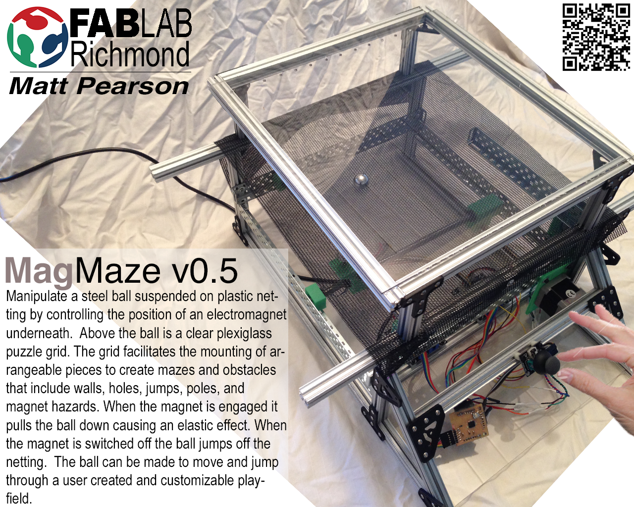
I wanted to do something fun. I wanted to do a game. In review of input and output possibilities, programming environments I am familiar with, and a desire to use as many new skills as possible, I landed on the MagMaze. This fully functional prototype acts as a play and puzzle surface wher you navigate a user constructed maze with a steel ball pulled, pushed, and bounced.
MagMaze Development - Skills Learned - R&D - What Worked and What Did Not - What I Learned - Bill of Materials - Fabduino and Coding - Future Enhancements
What is the MagMaze?
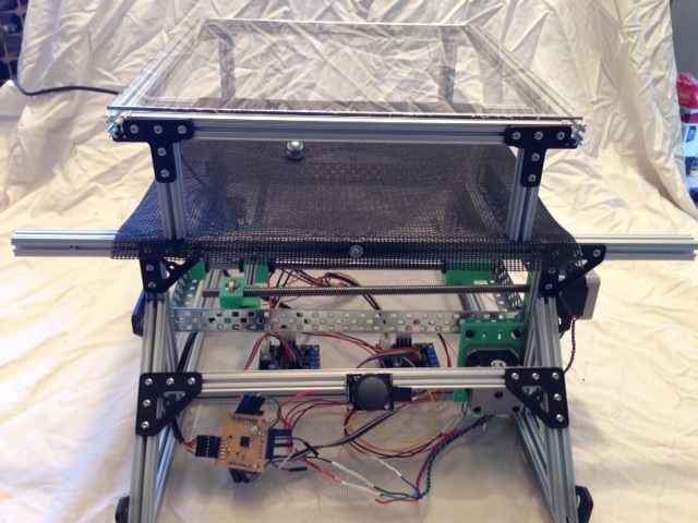
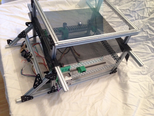
The MagMaze (pictured at left) allows the player to control the X/Y position of an electromagnet via joystick in a 300mmX 300mmX150mm enclosed box (Game Box). The electromagnet moves with varying speed based on the joystick input under a plastic netting stretched over the box. On the top of this netting rests a 3/4" polished steel ball suspended via the netting 1" above the electromagnet. Above the ball is a clear plexiglass 300mm X 300mm X 150mm partial box (Puzzle Grid) that rests on the Game Box. This Puzzle Grid has 5mm holes drilled every 15mm in X and Y to allow the user to insert puzzle pieces suspended under the clear plexiglass top. The player can create a puzzle or maze by pulling the Puzzle Grid off the Game Box and inserting a variety of puzzle pieces. The player can create many different kinds of mazes and obstacles that include walls, holes, jumps, poles, and magnet hazards.
The nature of the game lies in navigating the maze or just plyaing with the ball by using the electromagnet. When the electromagnet is engaged it pulls the ball down causing a storage of elastic potential energy in the plastic netting. When the electromagnet is switched off the energy is transformed to kinetic energy which causes the ball to jump off the netting. Thus, the ball can be made to move across the plastic netting and through suspended hoops and bars in the maze.
How this was developed
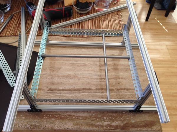
This game started out as an attempt at magnet levitation. I peformed tests with various electromagnets to see if I could code something that adjusted a series of electromagnets under a magnetic disk to balance the repulsion of the disk and net a "floating" disk. I quickly learned that the toroidal magnetic fields necessary, and their rapid constant adjustment, was beyond my coding capability at the moment. Aside from the challenges of coding an X/Y apparatus to respond to an analog joystick and move a mounting plate (for the electromagnet), the addition of the levitation was clearly not going to be attainable in the time frame necessary. I dove into the electronics and programming to explore the possibilities and learned how to control the stepper motors with the joystick inputs. Once I had the two two steppers and joystick conencted to the Arduino I started work on the mechanical enclosure. The Arduino Uno was used to prototype while I worked the kinks out of fabricating an home made Arduino called a Fabduino. I then started scavenging parts from various printers and other electronics to start work on the enclosure. The enclosure is prototyped with old metal from various robots and an extruded aluminum square rod called Openbeam. Openbeam allowed construction of the Game Box, it's X/Y control infrastructure and the Puzzle Grid.
What skills learned in the course were used to accomplish this:
Electronics production: Fabduino is the central control for user input via an analog joystick to output on two NEMA 17 stepper motors. It also controls the on/off of the electromagnet via a switch built into the joystick.
- Electronics production: Eagle, FAB ISP to burn the bootloader onto the Fabduino
- Programming with the Arduino IDE and Text editor
- Inputs: Analog joystick with incoporated switch, LEDs
- Outputs: Stepper motors
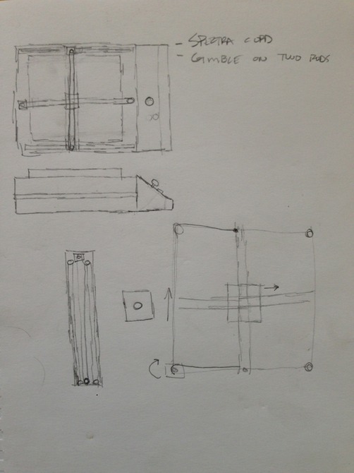
- CAD design: intial design using paper and pencil and then AI and TinkerCad for multiple areas
- 3D printing: the X and Y axis control rods connecting to the Stepper screw rods requires a custom part. I ended up with 7 differnet custom parts all printed with a 3D printer. I ended up using a printer called the Cube, by 3D Systems.
- Laser cutter: design of case and control mounting board (not in prototype, future enhancement). The entire case can be a press fit construction and allow for easy scaling of the project via kit form if desired.
What worked and what didn't
- I moved through three versions of the stepper mounting plate. V0.3 is current build being used.
- The mounting plate made of PLA is working very well and seems strong enough.
- When the motors work together they pull against each other. The steel rods do not remain perpendicular to the plane of motion causing binding. I will need to develop more than just a ledge for the rod to move along. I will need to add control rods and bearings to follow the control rod opposite the stepper motor rod.
- The magnet works well to draw the steel ball along the netting. However, the ball is only getting 5V and is rated for 12V. I need to power the ball through the computer power supply 12V and add a knob to vary the intensity of the magnet. This will allow the ball to sprung higher in the air.
- The Fabduino continues to be temperamental and I am going to mill the board over again after I manually tweak some traces in Gimp. I cannot get consistent operation out of it.
- The puzzle peg board needs to be designed in CAD and run through a CNC to get accurate peg holes for the puzzle pieces. I created a jig, but it needs to be perfect to work easily. An alternate to this could be to make the board out of acrylic and cut it on the Laser cutter.
- The puzzle pieces need to milled or 3D printed to get better tolerances for the peg board.
What I learned
- I learned a ton on how to code the joystick with the motors.
- I learned how bring together a whole system of mechanical parts and have them work in concert with user input.
- I learned about stepper motors and various driver boards. With easier access to the lab I can mill my own and use a custom design.
- That there are only 60 minutes in an hour and no matter what you do to squeeze more in you have to give stuff up to get to the finish line.
R&D
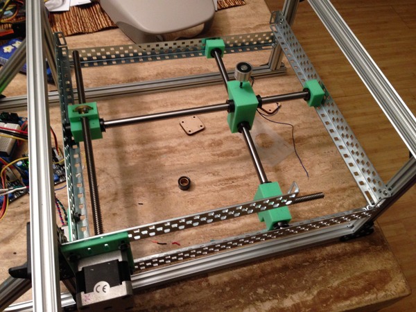
- Game Box
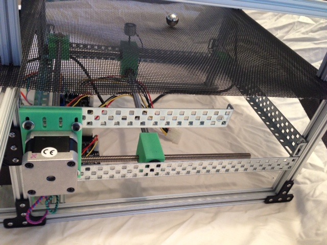
- The Game Box is constructed out 15mmX15mmX1000mm extruded aluminum stock from a company called Openbeam. The owner is great and helped me setup a classroom right after his kickstarter campaign. The Openbeam stock is connected using his "T" and "L" fittings and standard 3mm hardware. The box has VEX rails to serve as tracks for the steel rods which serve as the X and Y axises. The vex also uses the same connecting bolts.
- Puzzle Grid
- The puzzle grid is a five sided box made with Openbeam stock and hardware with Lexan. The Lexan is mounted in the grooves of the Openbeam stock. The Lexan has holes driled at 20mm intervals to form a grid that will accept the insertion of puzzle pieces which extend under the top of the Lexan going toward the plastic netting. This allows the user to change the obstacles for a variety of challenges.
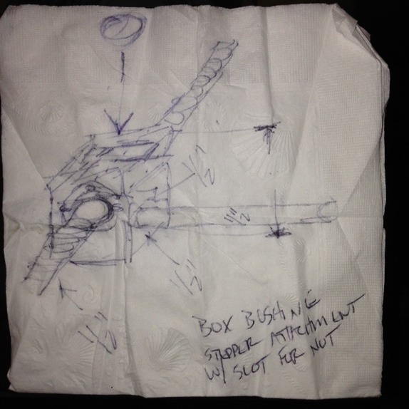
- Stepper control bar linkage boxes (qty 2)
- These boxes serve as the connector between the stepper motor drive shafts and drive shaft nut and the steel rods for both X and Y. These are custom designs and 3d printed in PLA. The X and Y boxes are not identical due to spacing in tracks.
- Cube workflow:
- Design part and export as .STL file.
- Open Cubify design software and import file.
- jClick the "heal" button on the software.
- Under settings: set to PLA, set to medium density for Cube 2, set to no rafts or supports
- Click on "Upload" button to export and save t thumb drive
- Cube workflow:
- X and Y axis linkage boxes
- V0.2 X axis linkage box on Thingiverse here.
- V0.2 Y axis linkage box on Thingiverse here.
- [UPDATE] Due to the nature of the blocks and linkages interferring with chassis connecting hardware, the stepper control plate had slides instead of holes designed into the plate so the plate can slide up and down to tune the linkage blocks.
- These boxes serve as the connector between the stepper motor drive shafts and drive shaft nut and the steel rods for both X and Y. These are custom designs and 3d printed in PLA. The X and Y boxes are not identical due to spacing in tracks.
- Magnet central mount: This box connects the two steel rods and serves as a mounting point for the electro magnet. This also allows the use of bearings to hold the steel rods. Part on Thingiverse.
- Rod pillow block: this connects on the opposite end of the guide rod to keep it level across the Game Box. Part on Thingiverse.
- Stepper motor mounting plate
- A component is available from Openbeam to mount NEMA17 stepper motors. However, the design did not quite meet my specification for mounting the motors in a hybrid Openbeam and VEX infrastructure. I designed custom plates and printed them out on a Cubify 3D printer. The printing ended up taking quite a bit of time as I attempted to make a new 3d printer operational (The Buccaneer by Pirate 3D), but it would not even load filament out of the box. The Cube 1 is a fairly solid printer that is dependable…usually. We will see if the PLA plates will hold up.
- Cube settings
- Print 1 set with raft enabled and at medium (strong) density.
- Probably need to remove the raft since this is a flat piece and added thickness.
- Cube settings
- These should probably be machined out aluminum plate for strength. The Shapeoko just arrived and is 6-8 hours of build time. Time that is not currently available to meet deadlines.
- Nema 17 stepper motor mounting plate V0.2 available on Thingiverse here.
- A component is available from Openbeam to mount NEMA17 stepper motors. However, the design did not quite meet my specification for mounting the motors in a hybrid Openbeam and VEX infrastructure. I designed custom plates and printed them out on a Cubify 3D printer. The printing ended up taking quite a bit of time as I attempted to make a new 3d printer operational (The Buccaneer by Pirate 3D), but it would not even load filament out of the box. The Cube 1 is a fairly solid printer that is dependable…usually. We will see if the PLA plates will hold up.
- Fabduino - I used a Fabduino and the Arduino IDE to control the motors, switches, and magnet.
Bill of Materials (spreadsheet coming)
- Openbeam components
- extruded aluminum
- 8 X 6"
- 8 X 15"
- plastic connectors
- 8 X "T" connectors
- 8 X corner connectors
- bolts, nuts, washers
- 144 M3 5mm bolts
- 144 M3 nuts
- 76 #8 washers
- 2 X Stepper motor mounts
- extruded aluminum
- VEX metal
- 4 "L" bracket strips
- Plastic netting
- 1 X 18"X18"
- Lexan
- 1 X 15"X15"X3/16"
- 10 X 1"X6"X3/16"
- Electronics
- 1 X Fabduino
- 2 X Stepper driver boards
- 1 X Joystick
- Varous connecting wires
- 2 X Stepper driver board to Fabduino
- 2 X Stepper power supply
- 2 X Stepper to driver board connectors
- 1 X electro magnet to Fabduino
- 1 X
- 1 X Electromagnet
- 2 X Stepper motors
- 1/2" steel ball
- 1 X Pushbutton switch (prototype switch is built-in to joystick)
- Computer power supply
- Miscellaneous
- 2X polished steel rods
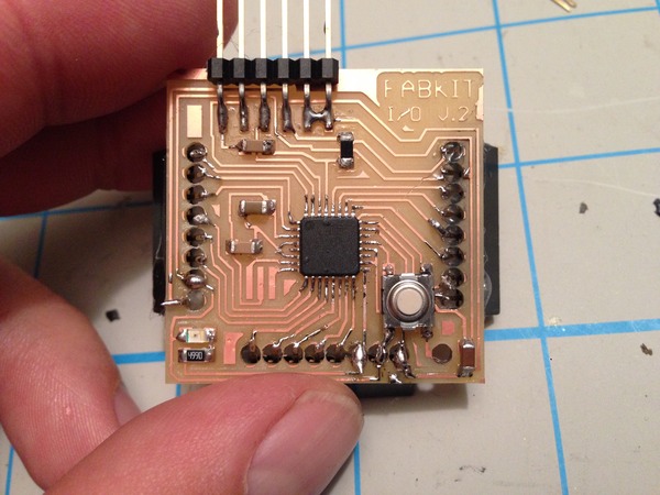
The Fabduino
I decided to use the Arduino IDE and fabricate a Fabduino to control the stepper motors, analog joystick, limit switches (future enhancement), electromagnet and anything else that was needed. I control the stepper motors with a Stepper Motor Driver v3.3 off an old Makerbot (version 1).
The Fabduino development from Week 10:
Arduino Code
//Magnetic Sphere Sphere Game
//This uses a dual potentiometer joystick to control two stepper motors in X and Y axis
//Need to add limit switches
//declare pins for X axis
int potPin = 1;
int Step_X = 13;
int Dir_X = 12;
int Enable_X = 8;
//declare pins for Y axis
int potPin2 = 2;
int Step_Y2 = 11;
int Dir_Y2 = 10;
int Enable_Y2 = 7;
//declare values
int Speed_X = 0; //step speed (delay between steps)
int val= 0;
int j = 0;
int Speed_Y2 = 0; //step speed (delay between steps)
int val2= 0;
int j2 = 0;
void setup() {
pinMode(Step_X, OUTPUT);
pinMode(Dir_X, OUTPUT);
pinMode(Enable_X, OUTPUT);
pinMode(Step_Y2, OUTPUT);
pinMode(Dir_Y2, OUTPUT);
pinMode(Enable_Y2, OUTPUT);
//Serial.begin(9600); // used to debug, must add writes after joystick valued reads
}
void loop() {
val = analogRead(potPin); // read the value from the sensor
j = val - 432; // 517 is center positions - how far from center?
j = abs(j); //absolute value
Speed_X = 10000/j; //This math inverts the value and scales as needed
//(value found through trial and error)
// The delay between steps will determine the speed of the motor
// So, delay up = speed down
val2 = analogRead(potPin2); // read the value from the sensor
j2 = val2 - 432; // 432 is center positions - how far from center?
j2 = abs(j2); //absolute value
Speed_Y2 = 10000/j2; //This math inverts the value and scales as needed
//(value found through trial and error)
// The delay between steps will determine the speed of the motor
// So, delay up = speed down
if (val >= 442){
digitalWrite(Enable_X,LOW); // enable
digitalWrite(Dir_X, HIGH); // Set direction
digitalWrite(Step_X,HIGH);
delayMicroseconds(2);
digitalWrite(Step_X,LOW);
delayMicroseconds(Speed_X);
}
if (val2 >= 442){
digitalWrite(Enable_Y2,LOW); // enable
digitalWrite(Dir_Y2, HIGH); // Set direction
digitalWrite(Step_Y2,HIGH);
delayMicroseconds(2);
digitalWrite(Step_Y2,LOW);
delayMicroseconds(Speed_Y2);
}
if (val <= 422) {
digitalWrite(Enable_X,LOW);// enable
digitalWrite(Dir_X, LOW); // Other direction
digitalWrite(Step_X,HIGH);
delayMicroseconds(2);
digitalWrite(Step_X,LOW);
delayMicroseconds(Speed_X);
}
if (val2 <= 422) {
digitalWrite(Enable_Y2,LOW);// enable
digitalWrite(Dir_Y2, LOW); // Other direction
digitalWrite(Step_Y2,HIGH);
delayMicroseconds(2);
digitalWrite(Step_Y2,LOW);
delayMicroseconds(Speed_Y2);
}
if (val <=442 && val >= 422) {
digitalWrite(Enable_X,HIGH); // disable the stepper X motor if the X axis is centered
}
if (val2 <=442 && val2 >= 422) {
digitalWrite(Enable_Y2,HIGH); // disable the stepper Y motor if the Y axis is in the center
}}
Future Enhancements aka What I would do differently:
- A planned enhancement is an additional knob to control the intensity of the electromagnet.
- Make stepper motor mounting plates out of ABS and or CNC them out of hi density plastic and/or aluminum on the Shapeoko.
- Create more puzzle pieces.
- Create pieces with bars, walls, small openings, jumps, magnet hazards, holes.
- Create custom rails via 3d print or CNC for steel rods.
- Add a separate button for controlling the magnet on/off state.
- Bump the voltage on the electromagnet to 12V.
- Add guides for the puzzle grid and perhaps velcro attachment points.
- Add an edge to the puzzle grid so the ball will not fall off.
- Add limit switches to prevent the motor for over extending.