Program the Hello World Board from Week 6
(and read the data sheet for the ATtiny44)
In this weeks video conference with the world we learned about the steps necessary to program a micro controller. I also learned some bad news, some good news and later some quite enlightening elements of micro controllers.
The Bad News…
I would not be allowed to buy an Arduino and program it for use in my final project. I am planning on a visual artistic representation of live environmental phenomena: Photo voltaic electricity generation, UV index, humidity, temperature, time, ambient pressure, and possibly ambient sound via decibels.
The Good News…
I would be allowed to build from scratch an Arduino and program it for use in my final project. Is this good news?
The Enlightening Learning…
This will play out more below in the steps I took to program the Hello World board. However, by diving into the white paper, playing with the Eagle software to design a board, and having learned how to fabricate the actual PCB, I have decided I do not need an Arduino. I will not make an Arduino. I will make a board that is far simpler and directly catered to my final project. Simpler, more efficient, costs less, and to be integrated into the visual artistic expression, not hidden in a box.
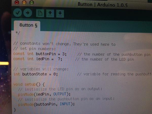
And the Programming Begins…or not…
What should be a straightforward connect it an program it turns into an epic journey down a rabbit hole. I am using the Arduino IDE to program my board using a straightforward set of tools. Unfortunately, installing the tools was the easy part! I installed and configure the following for this week's mission:
- The Arduino IDE Software e
- The ATtiny Board Files
- The FTDI Drivers
- I also needed to study the data sheet for the ATtiny44
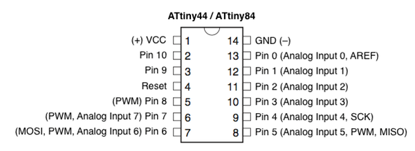
- Since I am using the Arduino IDE to program with for the moment I need this cheat sheet for the pins:
Once the IDE environment is setup you can proceed to burning the boot loader and then programming the board. You are not actually burning anything to the chip, bu this sets the fuse bits of the chip to run at 8MHz. I followed this tutorial to make all this happen: http://academy.cba.mit.edu/content/tutorials/akf/embedded_programming_arduinoIDE.html
And now, what did not work…
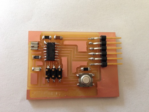
I tested the boards by toning them out and looking closely at all solder joints. Everything seems good. I kept getting this error:
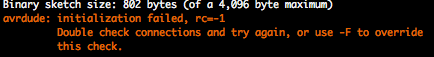
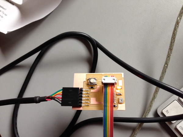
This error traces back to a bad connection, an incomplete solder joint, or something plugged in backwards. I once again test and test and test with a DMM the connections. Everything is fine. At some point I think I brick my chip on my programmer as it no longer will come up in System Information on my mac…
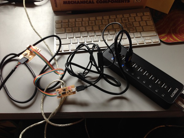
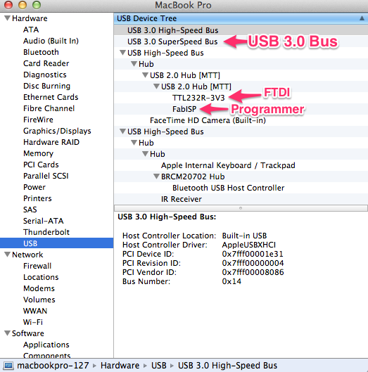
See below my final resolution, using a USB 2.0 external hub. My programmer, and the FTDI cable, will appear under the USB 3.0 bus, but it will give the above error. I only figured this out after bricking one chip, soldering in a new one, desoldering and soldering jumpers, looking for ages for forums and trying to reflow lots of solder joints. This shot below if of system information: click on the Apple in the top left of your OSX desktop and select about this mac, then more info. You will need to click on the below menu to pick USB.
Before I figured out it was the USB 3.0, at least in my case, I found a bad solder joint that had slipped by me. This chip is 8mm long. Notice the foot underneath the blob.
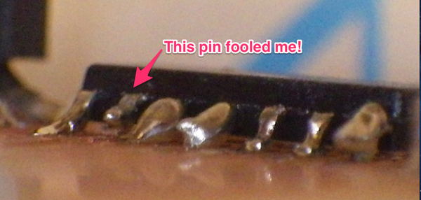
This second foot from the left of the ATtiny44 was soldered on top and when I toned it I would push down on the foot to make contact…then release and it would lose contact. Only I did not know this, till it occured to me it could happen. I looked close and sure enough when toned from the top of the foot it did not show a connection. Lesson learned, but I still got the same error.
I finally found a forum where a user had tried moving away from USB 3.0 and without a hub had to put the project on hold. Immediately upon trying a USB 2.0 hub it worked on the first try!