"Do the mechanical design for your final project."
I have changed the final project to something that is more fun and something that incorporates more of the skills I have learned in this course. It has become known simply as MagMaze.
What I did
I decided I wanted to do something fun. I wanted to do a game. In review of input and output possibilities, programming environments I am familiar with, and a desire to use as many new skills as possible, I landed on the Magnet Maze. This fully functional prototype acts as a play and puzzle surface wher you navigate a user constructed maze with a steel ball pulled, pushed, and bounced.
What is the Magnet Maze?
The Magnet Maze allows the player to control the X/Y position of an electromagnet via joystick in a 300mmX 300mmX150mm enclosed box: Game Box. The magnet moves with varying speed based on the joystick input under a plastic insect netting stretched over the box. On the top of this netting rests a 1/2" polished steel ball suspended via the netting 1" above the electro magnet. Above the ball is a clear plexiglass 300mm X 300mm X 150mm partial box (Puzzle Grid) that rests on the Game Box. This Puzzle Grid has holes 1/4" holes drilled every 15mm in X and Y to allow the user to insert puzzle pieces suspended under the clear plexiglass top. The player can create any maze by pulling the Puzzle Grid off the Game Box and inserting a variety of puzzle pieces to create many different kinds of mazes and obstacles that include walls, holes, jumps, poles, and magnet hazards.
The nature of the game lies in navigating the maze with the ball by using the magnet. When the magnet is engaged it pulls the ball down causing an elastic effect with the insect netting. When the magnet is switched off the ball jumps off the netting. In this way the ball can be made to move through suspended hoops and bars in the maze.
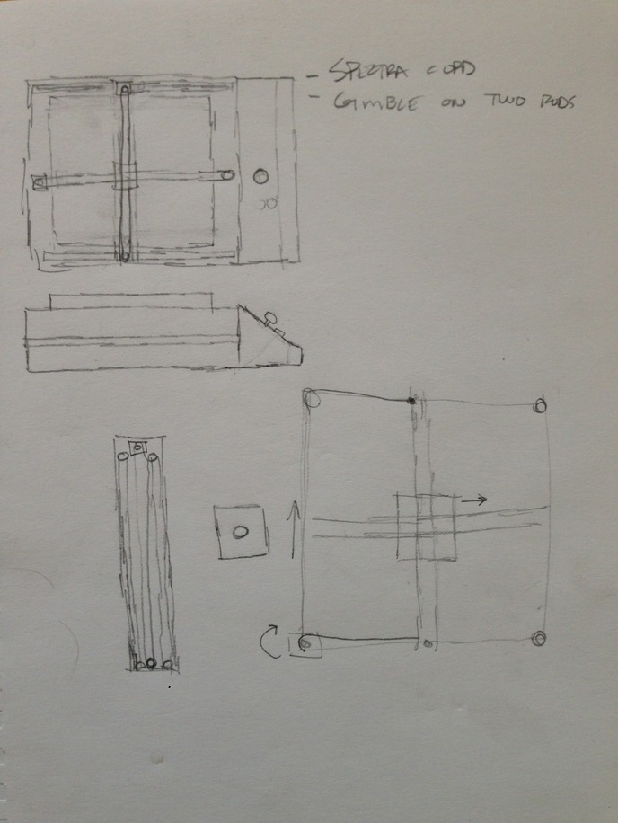
My design process tends to be a bit dreamy in the beginning taking shape on napkins and drawing paper where ever I happen to be. The mechanical design took shape my mixing the materials in my head and how they might be tested to work together. The programmitc logic of controlling an X/Y pair of axes has been done many times and I was confident I could make it work. I then started dumping things to paper with a pencil. Here are two sketches of a few.
After paper I head right to the materials and starting tinkering and playing. The materials at my disposal are generally old castaways. Old robots, printers, and electronic floatsam. Once I have played and tinkered with what is around, I am ready to design with a computer tool. I head to CAD and start creating my building blocks and putting them together. I am not yet at the competency level where I can have an inventory of parts and manipulate them quickly on a computer screen as in Adobe Inventor, but I am rapidly approaching that capacity.
I head to something simple that I can rapidly control and tweak and like Tinkercad for this. I can build sub assemblies and then combine them into one model. I also like to publish my work while in progress and take numerous pictures so I can refer back to where I have been. I have learned to have a love of history.
R&D
- Game Box
- The Game Box is constructed out 15mmX15mmX1000mm extruded aluminum stock from a company called Openbeam. The owner is great and helped me setup a classroom right after his kickstarter campaign. The Openbeam stock is connected using his "T" and "L" fittings and standard 3mm hardware. The box has VEX rails to serve as tracks for the steel rods which serve as the X and Y axises. The vex also uses the same connecting bolts.
- Puzzle Grid
- The puzzle grid is a five sided box made with Openbeam stock and hardware with Lexan. The Lexan is mounted in the grooves of the Openbeam stock. The Lexan has holes driled at 20mm intervals to form a grid that will accept the insertion of puzzle pieces which extend under the top of the Lexan going toward the plastic netting. This allows the user to change the obstacles for a variety of challenges.
- Stepper control bar linkage boxes (qty 2)
- These boxes serve as the connector between the stepper motor drive shafts and drive shaft nut and the steel rods for both X and Y. These are custom designs and 3d printed in PLA. The X and Y boxes are not identical due to spacing in tracks.
- Cube workflow:
- Design part and export as .STL file.
- Open Cubify design software and import file.
- jClick the "heal" button on the software.
- Under settings: set to PLA, set to medium density for Cube 2, set to no rafts or supports
- Click on "Upload" button to export and save t thumb drive
- Cube workflow:
- X and Y axis linkage boxes
- V0.2 X axis linkage box on Thingiverse here.
- V0.2 Y axis linkage box on Thingiverse here.
- [UPDATE] Due to the nature of the blocks and linkages interferring with chassis connecting hardware, the stepper control plate had slides instead of holes designed into the plate so the plate can slide up and down to tune the linkage blocks.
- These boxes serve as the connector between the stepper motor drive shafts and drive shaft nut and the steel rods for both X and Y. These are custom designs and 3d printed in PLA. The X and Y boxes are not identical due to spacing in tracks.
- Magnet central mount
- This box connects the two steel rods and serves as a mounting point for the electro magnet. This is also a custom design and allows the use of bearings to hold the steel rods.
- Stepper motor mounting plate
- A component is available from Openbear to mount NEMA17 stepper motors. However, the design did not quite meet my specification for mounting the motors in a hybrid Openbeam and VEX infrastructure. I designed custom plates and printed them out on a Cubify 3D printer. The printing ended up taking quite a bit of time as I attempted to make a new 3d printer operational (The Buccaneer by Pirate 3D), but it would not even load filament out of the box. The Cube 1 is a fairly solid printer that is dependable…usually. We will see if the PLA plates will hold up.
- Cube settings
- Print 1 set with raft enabled and at medium (strong) density.
- Probably need to remove the raft since this is a flat piece and added thickness.
- Cube settings
- These should probably be machined out aluminum plate for strength. The Shapeoko just arrived and is 6-8 hours of build time. Time that is not currently available to meet deadlines.
- Nema 17 stepper motor mounting plate V0.2 available on Thingiverse here.
- A component is available from Openbear to mount NEMA17 stepper motors. However, the design did not quite meet my specification for mounting the motors in a hybrid Openbeam and VEX infrastructure. I designed custom plates and printed them out on a Cubify 3D printer. The printing ended up taking quite a bit of time as I attempted to make a new 3d printer operational (The Buccaneer by Pirate 3D), but it would not even load filament out of the box. The Cube 1 is a fairly solid printer that is dependable…usually. We will see if the PLA plates will hold up.
- Fabduino - I used a Fabduino and the Arduino IDE to control the motors, switches, and magnet.