For this week we will learn how to fabricate a printed circuit board (PCB) to make a tool used in the programming of micro controllers. This tool is called FabISP. The fabrication of a PCB can be done several ways and I will be using a Roland Modela CNC to mill a PCB "blank."
Unfortunately, access to the equipment is not possible since our lab is in the midst of being created. The lab is in a portable at Kennedy High School in Richmond, CA, and the school is closed for break. Our team of three FabLabers have setup a time with our mentor to go over this week's lesson the following week.
I will continue this entry next week. So that time is not lost, I have moved ahead to week 5 and 3D printing and scanning. You can check that out in the Week 5 entry.
To be continued…
2/28/2014
Yesterday Fab Lab Instructor Mercedes Mane visited us at the temporary Richmond, CA Fab Lab for some much needed instruction for this weeks lesson. We each completed our own FabISP which will be used in future projects.
What we did:
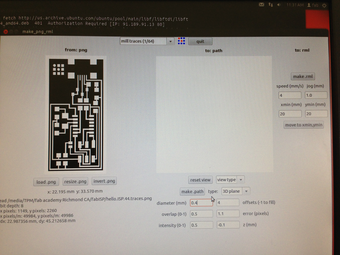
Downloaded and installed the Fab Modules (I used the already configure desktop with Linux). I am in the process of putting them on my laptop. The Fab modules are used to take the boad layout PNG file and convert it for the Modela to mill the board.
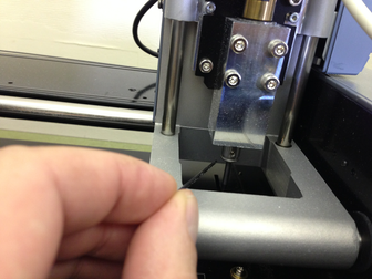
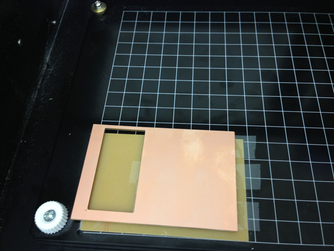
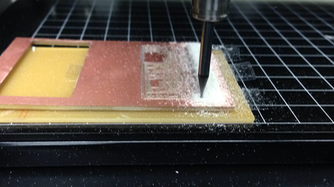
We put a 1/64th bit in and loaded the PNG up and sent it to the Modela. We first had to secure a blank to the milling deck to add a measure of safety so we don't mill it. Then we attached out blank to that with double sided tape.
I read the tutorials and watched the procedure unfold in front of me and noticed slight variations in the instruction. I asked for the process to be shown again and came up with this work flow.
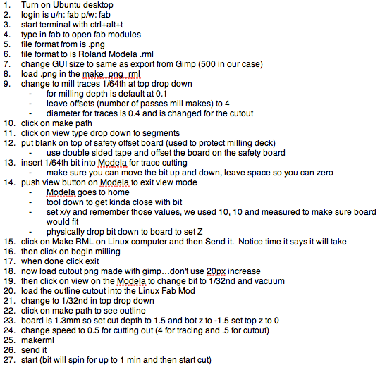
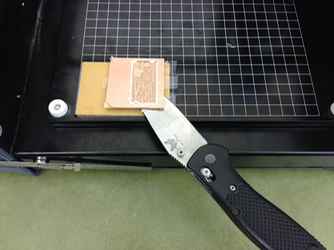
When we sent the file the board milled out the traces. We then changed the bit to 1/32nd and sent the PNG for the outline of the boad for it to be cut. We had to change the depth to accomplish this in the Fab Module.
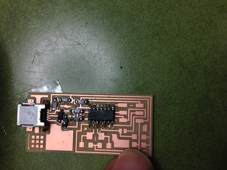
It was now time to pick the parts and solder them in place. I used Neil's trick of using solder wick for the miniscule solder points of the micro USB femail part and it worked great. (Mercedes has some sort of soldering gene…she was pretty amazing!).
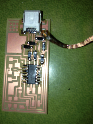
We have milled and stuffed the board and now need to program the board with AVR dude. AVR dude We then installed AVR dude to program the FAB ISP.
We followed this work flow (for a Mac):
- Mill the board
- Stuff the board
- Install the AVR dude tools. This is best done by following Lady Ada's tutorial
- Once you have the tools installed you can program the board with another already programmed FABisp. This sounded like a little chicken or the egg came first problem. Fortunately, you can buy boards already done and/or use a friences. We used Mercedes' FABisp.
- Download and unzip the firmware for the board from here
- Open a terminal window and navigate to where you unzipped the firmware
- Make the connections:
- Target FABisp is connected via USB and receiving 5V
- Programming FABisp is connected to the FABisp targe six pin header AND the USB of your computer
- From the directory you unzipped type these commands:
- make clean
- make hex
- make fuse
- make program
- If you receive errors you need to read them it usually comes down to checking the continuity of all your solders. I had a board fail due to a faulty chip that I fried some how.
- To see if things worked you can plug in your FABisp and then check the USB connection under system profiler. You should see an entry for FABisp.
- Remove the 0ohm resistor/solder bridge. This is only there when you program the board.
What I learned:
The FABisp is a fickle device and I know this is not the intention. I made three of these and the first two did not work due to my errors in soldering. I have never soldered surface mount electronics and needed to learn a delicate touch to complete them properly. I also did not understand the logic flow of programming the programmer and then removing a resistor to take the board out of programming mode. I became quite good at dumping solder on pins and then using solder braid to remove the unwanted.
Update: the programming of boards with this FABisp is continued extensively in nearly every week's assignment that involves electronics since the
What I would do differently:
It would be nice to have LEDs indicate whether you connected things properly to the header etc. Building in some feedback for the user to alert them to a backward connected cable etc. might be tough to do given the current design and work needed, but would make it easier for new students to see how things work. This would be a good extra credit tutorial for me to write-up since I built so many of these and tried so many variations of cable connections and computer setups.