This week...
This week we have been assigned to tweak the design of the Hello-World board by adding an input and an output. We will then use this board to learn how to program in week 8.
To do this we need to learn the following:
- How to use the Eagle PCB Design Software. This software allows us to create and mill printed circuit boards (PCB). We will use this to add components and recreate the trace routes on the board.
- How to take the output Eagle file and use Gimp (or another paint program) to prepare a cut file for the board.
- How to use the Fab Modules, and a little bit of Linux command line and Ubuntu, to create the path files to mill the traces.
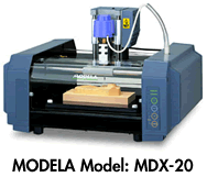
- Send the path file from the Fab Module to the Modela milling machine to machine a blank copper board.
- Once we get the board it is time to load it up and solder in the surface mount components.
My learning begins...
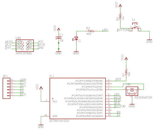
The Eagle software has a straightforward GUI and for me is intuitive. The interface updates two different displays: schematic and board layout. The schematic view is an easier to design interface since you can label and do virtual connections. Each electrical connection that needs to be made from one point to another will need to have a physical path to follow on the board which is displayed in the boad layout view. The board layout is what gets milled on the Modela.
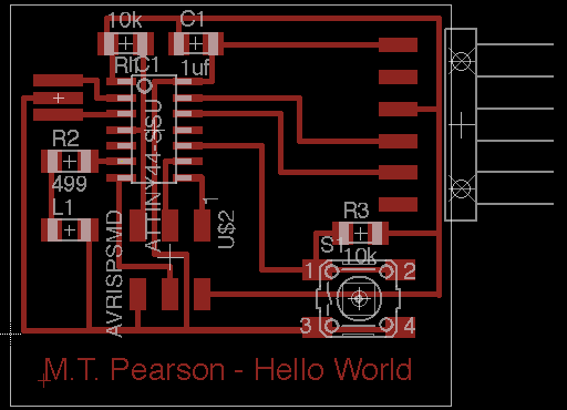
I decided to keep things simple since this is my first exposure to all of these tools. I added a button (input) and an LED (output). Here is my final schematic followed by the board layout:
After starting the soldering, we realized we do not have the correct resonator and have ordered the part: ECS-CR2-20.00-B-TR. Available at Digikey here. When this part arrives we will add it to our board and I will upload a picture of the finished board. Below you will find my raw step-by-step for taking the file to the Fab Module and milling with the Modela. Below tha are some pictures of failure and an attempt to hand mill. While I did get a workable "Frankenstein" board, I decided to remill the board. The first time around we did not invert the cut file to have it properly cut the board.
My raw step-by-step…
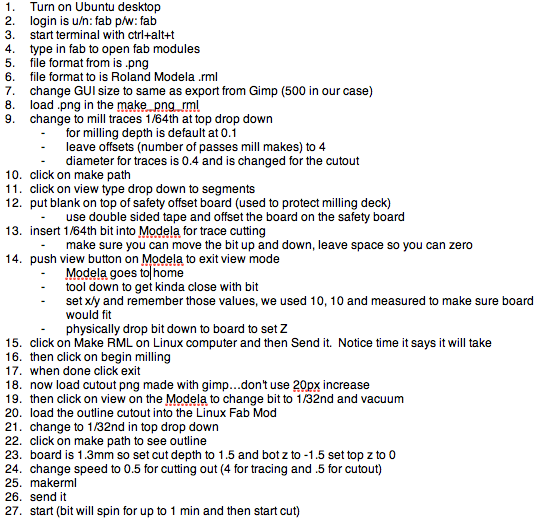
Some pictures of the milling (failed version)…
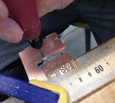
Update 3/28/2014
The order of resonators arrived and the board is now complete and ready for programming in week 8. I will put a picture here of the completed board soon. The resonators showed up and here is the completed board. I need to adjust the title of the board done in Eagle which ws too fine to come out properly. I will adjust in
What I learned:
Programming with the FABisp took me well over 75 attempts and it ended up being the computer I was using and a problem with USB 3.0 apparently. When I installed all the tools for the third time on an older Mac things worked the first time. I had also assumed that the green wire was ground when connecting as in houses, but it is infact the black wire. I knew this, but overlooked it in my repeated connections.
What I would do differently:
I arranged things manually in Eagle and created a name plate on the bottom. As you can see, it did not come out and needs to be done in thicker lines manually using Gimp or another paint program. I also don't like the extra copper all over the place, but it saves time to not have to remove it. I like thicker traces and easier to see connections.