Mechanical / Machine Design
Tasks
 '
'
Summery
 '
'
 '
'
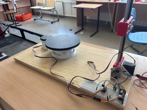
In this week we are maked a automatic 3d scanner with stepper motor
Development Process
 '
'
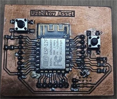
To control all the electronics, I used a custom board that I make . The board is based on an 8266 microcontroller, which offers high performance and built-in Wi-Fi connectivity. This microcontroller can simultaneously control a stepper motor and send or receive data via Wi-Fi, making it an ideal choice for automation projects. On the board, I included dedicated signal pins for connecting the stepper motor driver and other peripheral components. This design provides flexibility and scalability for future improvements to the system.
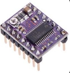
Stepper motor and Driver
 '
'
 '
'
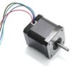
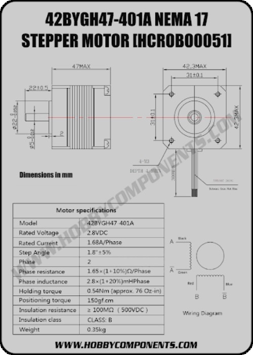
stepper motor 42bygh47 401a (2x) ,Drv8825 (2x), Capacitor 100µF(1x)
specification of motor
 '
'
I connected two DRV8825 stepper motor drivers to my custom ESP-12E board and then wired both stepper motors to their respective drivers. Since my board does not have a built-in USB programmer, I used a USB-TTL adapter to flash the firmware.
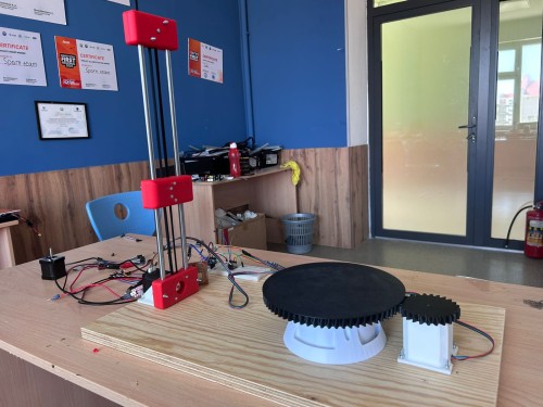
For the 3D scanner, one motor was responsible for rotating the object on the turntable, and the second motor was used to move the sensor up and down along the vertical axis. This way we could scan the full geometry of an object by combining rotation and vertical movement.
However, when I first tested the system, the ESP-12E kept rebooting every time both motors tried to move at the same time. After researching the issue, I discovered that the problem was caused by insufficient power supply — two motors drawing current simultaneously caused voltage drops on the logic rail. To fix this, I used two separate laboratory power supplies:
One for the ESP-12E board (3.3V logic) One for both stepper motors (12V, to provide enough torque and current without affecting the microcontroller)
After separating the power rails and adding 100µF decoupling capacitors across each driver's VMOT pin, everything worked stable. Both motors ran smoothly and the scanning motion was consistent enough to capture accurate geometry of the object.Sonnet 4.6Adaptive
problem
I connected two DRV8825 stepper motor drivers to my custom ESP-12E board and wired both stepper motors to their respective drivers. Since my board does not have a built-in USB programmer, I used a USB-TTL adapter to flash the firmware.
After wiring everything up, I wrote a simple test code to check if both motors were responding — basic step and direction signals to make them rotate forward and backward.
However, when I first powered the system, the motors were not moving at all — they were just buzzing and vibrating in place. I checked the wiring and the code multiple times but found no mistakes. After thinking about it, I realized the issue was the power supply voltage. I was providing only 8–9V to the motors, which was not enough for the DRV8825 to drive the stepper motors properly.
#define STEP_PIN 16
#define DIR_PIN  14
#define EN_PIN   0

void setup() {
  pinMode(STEP_PIN, OUTPUT);
  pinMode(DIR_PIN,  OUTPUT);
  pinMode(EN_PIN,   OUTPUT);

  digitalWrite(EN_PIN,  LOW);
  digitalWrite(DIR_PIN, HIGH);
}

void loop() {
  digitalWrite(STEP_PIN, HIGH);
  delayMicroseconds(800);
  digitalWrite(STEP_PIN, LOW);
  delayMicroseconds(800);
}
Solve problem
And i solve this problem
The motor responsible for lifting the phone was not generating enough torque to actually raise it. At first, when I powered the system at 8–9V, the motor was only buzzing and the phone mount was not moving at all — it would just sit in place and vibrate slightly.
After testing different voltage levels, I found that increasing the supply to 11V gave the motor enough torque to lift the phone smoothly along the vertical axis. The movement became stable and consistent, which was important for the 3D scanning process since the phone needed to move at a steady pace to capture accurate geometry of the object.
and Test a motor
final code

#define STEP1_PIN 16
#define DIR1_PIN  14
#define STEP2_PIN 5
#define DIR2_PIN  4
#define EN_PIN    0

void step(int stepPin, int steps, int delayUs) {
  for (int i = 0; i < steps; i++) {
    digitalWrite(stepPin, HIGH);
    delayMicroseconds(delayUs);
    digitalWrite(stepPin, LOW);
    delayMicroseconds(delayUs);
  }
}

void setup() {
  pinMode(STEP1_PIN, OUTPUT);
  pinMode(DIR1_PIN,  OUTPUT);
  pinMode(STEP2_PIN, OUTPUT);
  pinMode(DIR2_PIN,  OUTPUT);
  pinMode(EN_PIN,    OUTPUT);

  digitalWrite(EN_PIN,   LOW);
  digitalWrite(DIR1_PIN, HIGH);
  digitalWrite(DIR2_PIN, HIGH);

  for (int i = 0; i < 10; i++) {
    step(STEP1_PIN, 200, 800);
    delay(300);
    step(STEP2_PIN, 50, 800);
    delay(300);
  }

  digitalWrite(EN_PIN, HIGH);
}

void loop() {}
it turning motor bed 200ticks is a full turning 360degree
After when first motor turn a bed second motor up a phona 50ticks
and it repeat 10 times
Conclusion
During this week's assignment I learned a lot about controlling stepper motors with the DRV8825 driver and ESP-12E. Working on the electronics for the 3D scanner gave me practical experience that I could not get just from reading documentation.
The main problem I faced was that the motors were not moving and only buzzing when I first powered the system. I spent time checking the wiring and the code, but everything looked correct. Eventually I figured out that the issue was simply not enough voltage — running at 8–9V was insufficient for the DRV8825 to drive the motors under load. Increasing the supply to 11V solved the problem immediately.
From this experience I learned that stepper motors are very sensitive to power supply voltage, especially when they are working under load. I also learned how to use a USB-TTL adapter to flash firmware on a board without a built-in programmer, and how to wire two independent motor drivers to a single microcontroller sharing one enable pin.
Overall this week helped me understand not just the electronics side but also how mechanical load directly affects the electrical requirements of the system.