Week 10 - Networking and Communications
Individual
1. Introduction
Individual Assignment: Protocols and Web Integration For the individual task, I am focusing on implementing a multi-layered communication system using the following technologies:
Wired Protocols (UART & I2C): I explored the fundamentals of UART (Universal Asynchronous Receiver-Transmitter) for serial debugging and data transfer, as well as I2C (Inter-Integrated Circuit) to efficiently communicate with peripheral devices using a shared bus and specific device addressing.
Local Web Server (HTTP): Using a microcontroller, I developed a local web server. This allows for wireless interaction over a local network, where an HTTP interface serves as the control panel.
LCD Control: The primary output for this network node is an LCD display. By accessing the web server from a browser, I can send commands and data to the microcontroller, which then processes the requests and updates the LCD in real-time.
Chapter: UART Communication (Arduino Uno & ESP8266)
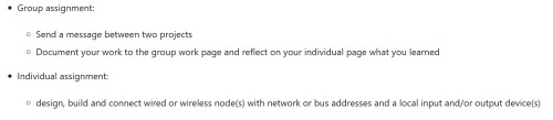
For this part of the project, I implemented a serial communication link using the UART (Universal Asynchronous Receiver-Transmitter) protocol. The goal was to establish a hardware-level connection between an Arduino Uno and an ESP8266 to demonstrate basic data transmission and remote triggering.
The Concept and Implementation The setup involves two microcontrollers acting as a transmitter and a receiver:
Transmitter (Arduino Uno): A physical button is connected to the Arduino. When the button is pressed, the Arduino sends a specific data packet (a signal) through its serial port.
Receiver (ESP8266): The ESP8266 constantly listens to the serial line. Once it detects the signal from the Arduino, it triggers a high signal to an onboard or external LED, turning it on.
Understanding UART Wiring To make this communication possible, four primary pins are used. It is crucial to remember that UART is a "cross-over" protocol, meaning the transmission line of one device must connect to the receiving line of the other.
TX (Transmit): This pin sends data. The TX pin of the Arduino connects to the RX pin of the ESP8266.
RX (Receive): This pin receives data. The RX pin of the Arduino connects to the TX pin of the ESP8266.
GND (Ground): This is the most critical connection. Both boards must share a Common Ground to ensure they have the same reference voltage for the data signals. Without a shared GND, the communication will be noisy or non-functional.
VCC (Power): I connected ESP8266 to 3.3 on arduino uno
After connecting i make code for Esp8266 and Arduino uno
Code for Esp8266
#define LED_PIN 2

void setup() {
  Serial.begin(9600);
  pinMode(LED_PIN, OUTPUT);
  digitalWrite(LED_PIN, HIGH);
}

void loop() {
  if (Serial.available()) {
    String cmd = Serial.readStringUntil('\n');
    cmd.trim();

    if (cmd == "ON") {
      digitalWrite(LED_PIN, LOW);
    }
    else if (cmd == "OFF") {
      digitalWrite(LED_PIN, HIGH);
    }
  }
}
And for Arduino
const int buttonPin = 3;
int lastState = HIGH;

void setup() {
  Serial.begin(9600);
  pinMode(buttonPin, INPUT_PULLUP);
}

void loop() {
  int state = digitalRead(buttonPin);

  if (state == LOW && lastState == HIGH) {
    Serial.println("ON");
    delay(50);
  }
  if (state == HIGH && lastState == LOW) {
    Serial.println("OFF");
    delay(50);
  }

  lastState = state;
}
And a Result
Chapter: I2C Communication and Signal Debugging
Following the UART setup, I transitioned to the I2C (Inter-Integrated Circuit) protocol to manage a visual output interface. This phase involved hardware addressing, software implementation, and physical signal verification using an oscilloscope.
1. Hardware Connection and Address Scanning
The I2C display was integrated using a 4-wire interface to minimize pin usage on the microcontroller:
VCC: Connected to 5V to provide stable power for the logic and backlight.
GND: Connected to the common ground.
SDA (Serial Data): The bidirectional line for data transfer.
SCL (Serial Clock): The line carrying the synchronization clock signal.
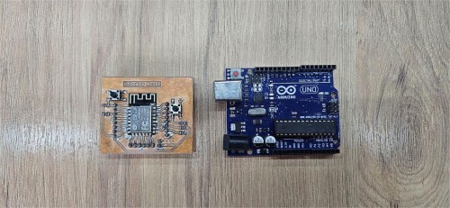
Since every I2C device requires a unique hex address to communicate, my first step was to run an I2C Scanner code. This script polls the bus for responsive devices. Without identifying the correct address (typically 0x27 or 0x3F), the microcontroller cannot send commands to the specific hardware. The scanner successfully identified the display, allowing me to proceed to the firmware implementation.
code for scanning address
#include <Wire.h>

void setup() {
  Wire.begin();
  Serial.begin(115200);
  Serial.println("\nI2C Scanner");
}

void loop() {
  byte error, address;
  int nDevices;
  Serial.println("Scanning...");
  nDevices = 0;
  for(address = 1; address < 127; address++ ) {
    Wire.beginTransmission(address);
    error = Wire.endTransmission();
    if (error == 0) {
      Serial.print("I2C device found at address 0x");
      if (address<16) {
        Serial.print("0");
      }
      Serial.println(address,HEX);
      nDevices++;
    }
    else if (error==4) {
      Serial.print("Unknow error at address 0x");
      if (address<16) {
        Serial.print("0");
      }
      Serial.println(address,HEX);
    }
  }
  if (nDevices == 0) {
    Serial.println("No I2C devices found\n");
  }
  else {
    Serial.println("done\n");
  }
  delay(5000);
}
2. LCD Implementation and Data Display
Once the address was confirmed, I utilized a second code based on the LiquidCrystal_I2C library. This script initializes the display and handles the transmission of strings over the I2C bus.
Logic: The microcontroller sends data packets via the SDA line, which the I2C backpack on the LCD translates into character commands.
Result: The display successfully initialized and printed the designated text, confirming that the 5V power supply and logic levels were stable.
#include <Wire.h>
#include <LiquidCrystal_I2C.h>

LiquidCrystal_I2C lcd(0x27, 16, 2);

void setup() {
  Wire.begin(4, 5); // SDA=D2, SCL=D1
  lcd.init();
  lcd.backlight();

  lcd.setCursor(0, 0);
  lcd.print("Hello World!");

  lcd.setCursor(0, 1);
  lcd.print("ESP8266 + LCD");
}

void loop() {}
3. Oscilloscope Signal Analysis
To verify the integrity of the data transmission and check for electrical noise, I connected an oscilloscope to the SDA and SCL lines.
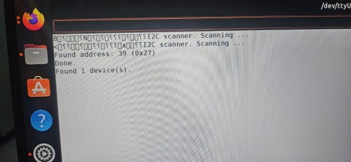
The oscilloscope capture provides a visual representation of the communication protocol:
SCL Signal (Clock): Shows a steady stream of square waves, representing the clock pulses that synchronize the timing of the data transfer.
SDA Signal (Data): Displays the varying logic levels (high/low) that represent the actual bits of information being sent to the LCD.
By analyzing these waveforms, I confirmed that the signal transitions (rising and falling edges) were sharp and within the acceptable voltage thresholds for the I2C standard. This hardware-level validation ensured that the communication was robust and free from data corruption.
Chapter: Web Server and Wireless Control
For the final part of the networking assignment, I developed a system to control the LCD display wirelessly. I used an ESP8266 to host a local web server, creating a bridge between a browser interface and the physical hardware.
1. Web Interface Design
I used AI assistance to generate the front-end design of the control page. The goal was to have a clean, functional interface with:
An input field for text.
A "Send" button to transmit data.
A dark-themed CSS style for better visibility.
JavaScript (Fetch API): This allows the message to be sent to the microcontroller without refreshing the entire webpage.
2. How it Works (The Logic)
The ESP8266 is configured as an Access Point (AP). When a device connects to its Wi-Fi network and navigates to the IP address 192.168.4.1, the following process occurs:
Request: The user types a message (e.g., "Hello") on their phone and presses "Send".
Transmission: The browser sends an HTTP GET request to the /send path on the ESP8266.
Processing: The ESP8266 extracts the text from the request using the server.arg("text") function.
Output: The microcontroller then sends this text to the LCD via the I2C bus (using the SDA and SCL pins).
3. Implementation and Testing
I integrated the AI-generated HTML/JS into my Arduino sketch by storing it as a string variable. In the video demonstration, you can see the end-to-end workflow:
Connecting to the "ESP8266-LCD" Wi-Fi network.
Accessing the control panel via a smartphone browser.
Sending text that immediately appears on the 16x2 LCD screen.
And this is code
#include <ESP8266WiFi.h>
#include <ESP8266WebServer.h>
#include <Wire.h>
#include <LiquidCrystal_I2C.h>

const char* ap_ssid = "ESP8266-LCD";
const char* ap_pass = "12345678";

ESP8266WebServer server(80);
LiquidCrystal_I2C lcd(0x27, 16, 2);

void handleRoot() {
  String html = "";
  html += "<!DOCTYPE html><html><head>";
  html += "<meta charset=UTF-8>";
  html += "<meta name=viewport content=width=device-width,initial-scale=1>";
  html += "<title>LCD Control</title>";
  html += "<style>";
  html += "body{font-family:Arial;text-align:center;padding:20px;background:#1a1a2e;color:white}";
  html += "h2{color:#00d4aa}";
  html += "input{width:80%;padding:12px;font-size:18px;border-radius:8px;border:none;margin:10px 0}";
  html += "button{padding:12px 30px;background:#00d4aa;color:black;font-size:18px;border:none;border-radius:8px;cursor:pointer}";
  html += "#status{margin-top:15px;color:#00d4aa}";
  html += ".lcd{background:#9FE1CB;color:#04342C;padding:15px;border-radius:8px;font-family:monospace;font-size:20px;margin:20px auto;width:280px}";
  html += "</style></head><body>";
  html += "<h2>LCD Control</h2>";
  html += "<div class=lcd id=lcdDisplay>Hello!</div>";
  html += "<input type=text id=msg maxlength=16 placeholder=Type text...>";
  html += "<br><br>";
  html += "<button onclick=sendText()>Send to LCD</button>";
  html += "<div id=status></div>";
  html += "<script>";
  html += "function sendText(){";
  html += "var msg=document.getElementById('msg').value;";
  html += "fetch('/send?text='+encodeURIComponent(msg))";
  html += ".then(function(){";
  html += "document.getElementById('status').textContent='Sent!';";
  html += "document.getElementById('lcdDisplay').textContent=msg;";
  html += "});}";
  html += "</script></body></html>";
  server.send(200, "text/html; charset=utf-8", html);
}

void handleSend() {
  if (server.hasArg("text")) {
    String msg = server.arg("text");
    lcd.clear();
    lcd.setCursor(0, 0);
    lcd.print("Message:");
    lcd.setCursor(0, 1);
    lcd.print(msg.substring(0, 16));
    server.send(200, "text/plain", "OK");
  }
}

void setup() {
  Wire.begin(4, 5);
  lcd.init();
  lcd.backlight();
  lcd.clear();
  lcd.print("Starting...");

  WiFi.softAP(ap_ssid, ap_pass);

  lcd.clear();
  lcd.setCursor(0, 0);
  lcd.print("WiFi:ESP8266-LCD");
  lcd.setCursor(0, 1);
  lcd.print("192.168.4.1");

  server.on("/", handleRoot);
  server.on("/send", handleSend);
  server.begin();
}

void loop() {
  server.handleClient();
}
Conclusion: Networking and Communications
The work completed this week successfully demonstrates the implementation of multiple communication layers, moving from low-level wired protocols to a functional wireless IoT interface. Through practical experimentation and hardware debugging, I have gained a comprehensive understanding of how data is synchronized and transmitted between different systems.
Summary of Achievements Protocol Integration: I successfully established a hardware link using UART for board-to-board communication and used the I2C bus to manage a character display. These experiments highlighted the importance of shared ground, proper addressing, and timing.
Signal Integrity: By using an Oscilloscope to capture SDA and SCL waveforms, I was able to verify the physical truth of the data transmission. This hardware-level validation confirmed that the signals were clean and met the required logic thresholds.
Wireless Control: I successfully developed a local HTTP Web Server on the ESP8266. By integrating a custom UI, I proved that a wireless device could act as a remote controller, triggering physical hardware outputs in real-time via a browser.
Final Reflection This week proved that communication is the backbone of embedded systems. Whether it is a simple serial trigger between two microcontrollers or a complex web-to-hardware bridge, understanding the underlying protocols is essential for building reliable electronic systems. The success of the final demonstration—controlling the LCD via a smartphone—confirms that the designed node is fully functional, uniquely addressable, and ready for more complex networking applications.