This page covers two Fab Academy weeks — Applications and Implications + Project Development — and also serves as the final-project showcase. The rubric below is the union of all three.
Applications and Implications
Project Development
Final project showcase
The Final Project
Problem
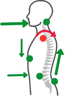
Long hours at a desk or lab can silently damage your posture. Poor alignment affects the spine and ribcage, causes certain muscles to become inactive while others are chronically overworked — leading to pain, discomfort, and long-term injury.
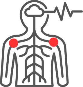
Solution A lightweight wearable device that corrects posture in real time by tracking two fixed points on the shoulders. By monitoring shoulder alignment, the device guides the neck, back, and core into a healthier position — making good posture feel natural and comfortable. Over time, it trains the body-mind connection so correct posture becomes automatic.
Experience As a 200-hour certified yoga instructor with a background in body mechanics and mobility anatomy, I understand posture from the inside out. Being part of the Fab Academy network gives me the tools to actually build this — and I'll be the very first one to wear it.
The Final Project process
This page describes what I selected from each of the previous weeks for my final project, as well as the workflows and main outputs. I will also link the work from the previous weeks related to each of these tasks as I go.
The start:
This is the schedule I followed to finalize my final project. From the first day of my Fab Academy journey, I knew what my final project would be, but I also had a lot of new skills to learn and practice. The previous weeks document my learnings, failures, and achievements as I worked to keep the schedule rather than just ticking off tasks, documenting as I went and learned.
The challenges:
It was not an easy journey — in the 2026 cohort I had several unexpected challenges. First, the escalating war in the Middle East affected the lead time for getting all the parts I needed, which caused a huge delay in the project. It also forced me to reuse components from previous devices or models and to make some changes to the final project. Another challenge, also due to the war, was its effect on my management of WRO in Kuwait (you can learn more about it here): I had to redo, restructure, and reimplement the full WRO project in a different way to adapt to the Kuwaiti government's regulations for running the competition. Before joining Fab Academy I made sure my WRO project would be running smoothly in April, May, and June, so I would have the time to focus on my final project. But unfortunately, due to the escalation in the region and the war, I had to reduce everything for WRO during the most critical time in Fab Academy, and I had to take 3 weeks off to finish my country-level responsibilities.
Documentation:
I kept Dreamweaver open as I worked on the project, making sure to document and write what I was doing and to take photos in the same sequence. I first added the text, then — after resizing the pictures and adding my comments on them — I connected the main ones to the related sections. I also pulled references from my previous assignments to describe more details, and I kept documenting the missing assignments where they overlapped with the final project. My first objective was to finish the final project.
Use of AI:
I used different AI tools to help me finalize all the tasks. Claude Desktop was mainly used to review my documentation — spelling, grammar, refining phrases for clarity, adding keywords from Fab Academy assignments and methodologies, and surfacing sections I had forgotten to add. I connected it directly to my local folder; this is the audit report for the changes made.
I also used Google Gemini as my virtual coach to assist me through the implementation tasks (MicroPython on the clip, App Inventor blocks, ESP-NOW pivot in Week 16). (Gemini conversation report — to be added.)
The reason I used two different AI tools is to avoid cross-task hallucinations when I switch between very different rule sets (documentation review vs. code generation). I tried to be very clear with my prompts so I could use AI to my benefit — not to run into errors that would force me to repeat work and re-derive workflows.
Emotional support:
While going through the schedules and documentation in Fab Academy 2026, I came across the FabLab epic song. I'd heard it the first Wednesday at FabLab, but in my last week I related to it in a very different way — I kept playing it when I felt stuck and exhausted. I surely don't want to have my name added to Luciana's list. 🙂
Final Project schedule
The following is the schedule I created when I came back to focus on Fab Academy, starting the 15th of May 2026. The main objective was to get the final project done, then use the remaining time to document and complete the assignments I had left behind. The last day on the calendar is June 3, 2026. X represents the number of days in the week I worked on this task
Task
W01
W02
W03
W04
W05
W06
W07
W08
W09
W10
W11
W12
W13
W14
W15
W16
W17
W18
01| Ideation and Sketching
X
X
X
X
X
-
-
-
-
02| Electronic Production
Selecting the components
PCB Design
PCB Milling
Soldering the components
XX
XXX
XXX
XXX
-
-
-
-
XX
XXXX
XXXX
XXXX
03|01| Coding "Microcontroller"
Sensors Code Setup
Functional Code on the clip
Logic testing
XXX
XXX
XXX
-
-
-
-
XXX
XXXX
XXXXX
XXXXX
03|02| Coding — App Interface
Design
Block programming
App ↔ clip communication
-
-
-
-
XXX
XXX
XXX
XXXXX
04|02| Clips Packaging
3D design — FreeCAD
3D printing
Assembly
Cover moulding
XXX
-
-
-
-
XX
XXXXX
04|03| Wooden Case
CAD Design
Laser Cut
Assembly
XXX
XXX
-
-
-
-
XXX
XXXX
Evaluation and testing
-
-
-
-
XX
XXXXX
XXXXX
XXXXX
Documentation
XXX
XXX
XXX
XX
XX
XX
X
XXXX
XXXX
XXX
-
-
-
-
XXX
XXXXX
XXXXX
XXXXX
The Workflows
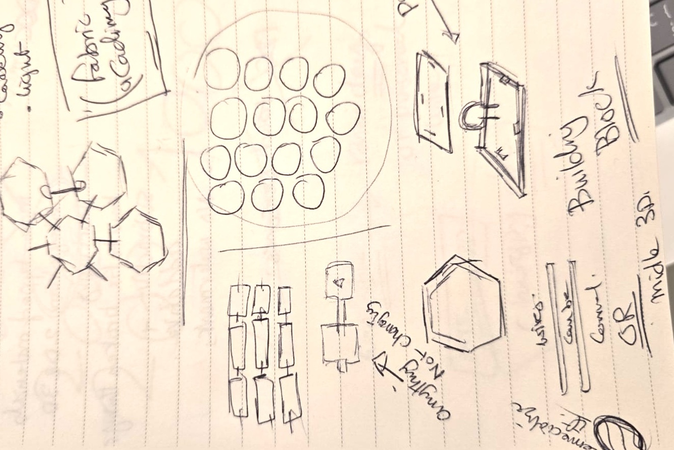
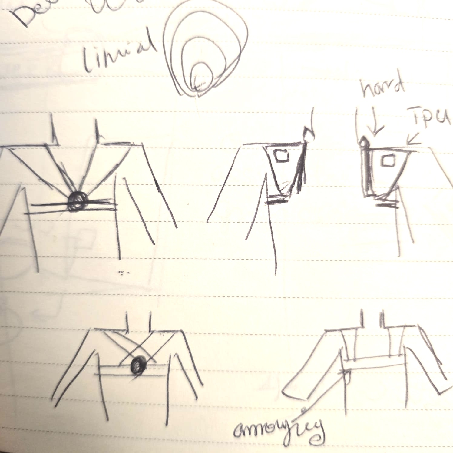
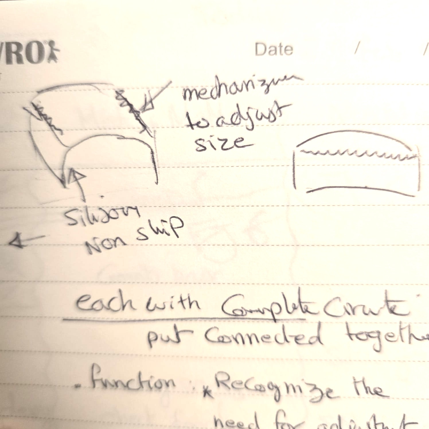
01| Ideation and Sketching
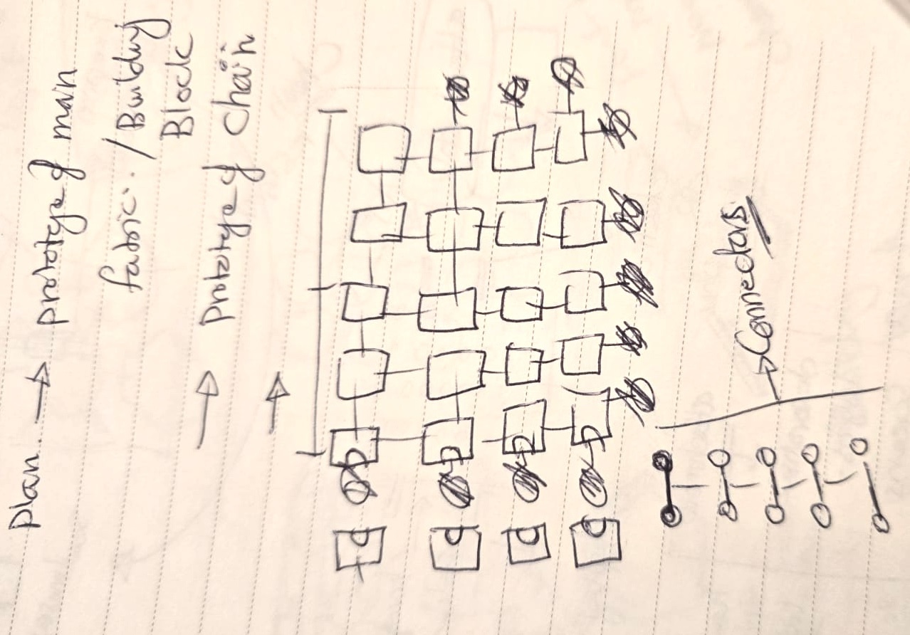
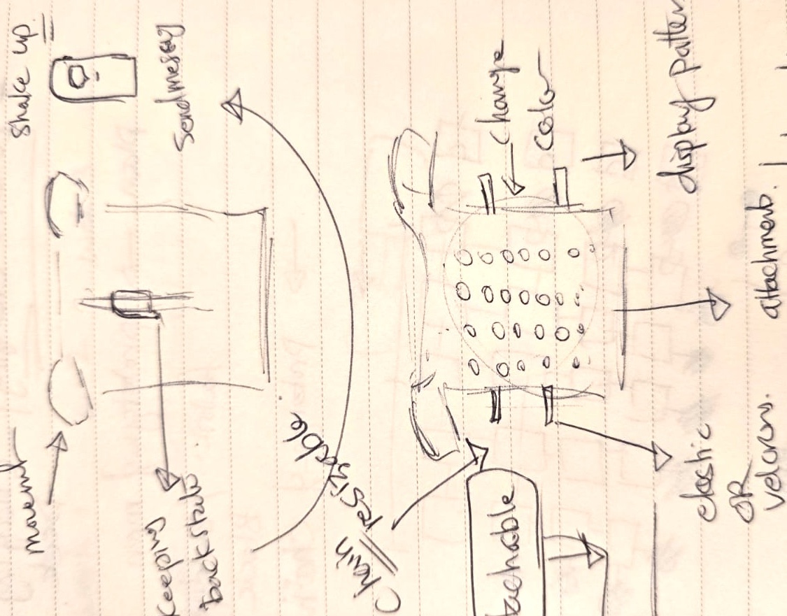
As I progressed through the weeks and got more exposure to my colleagues' projects, I kept simplifying the design. I created a version with a flexible strap, but wiring was an issue. I started with a full vest, then moved to a hanger, then to a shoulder strap, and finally to clips that are universal across different ages and genders — wearable over the clothes or directly on the skin.
02| Electronic Production
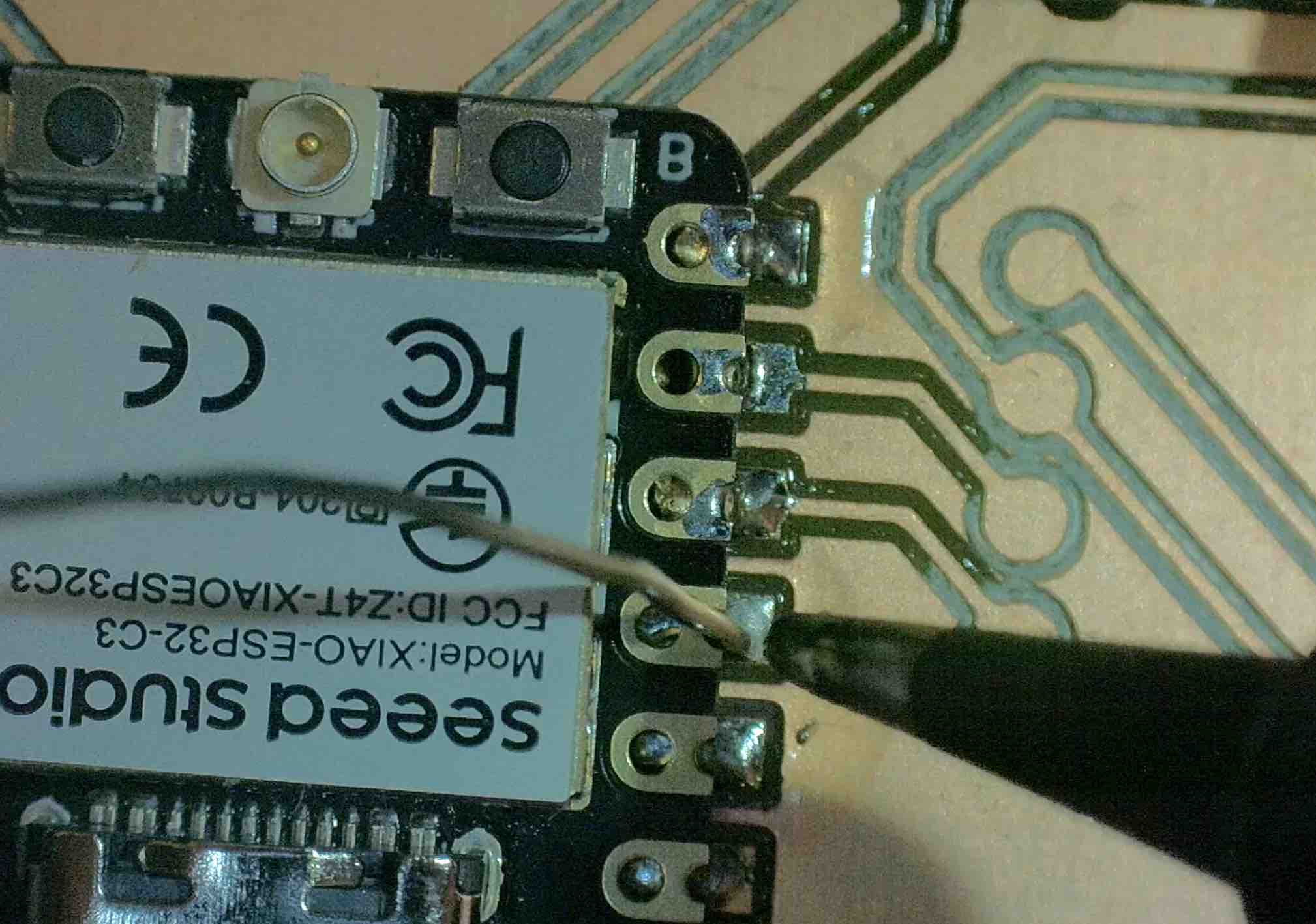
02|01| Selecting the components
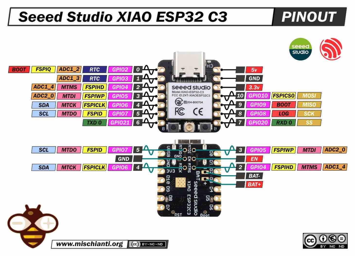
After all the research and studies made in Embedded Programming week, I selected the ESP32-C3 XIAO for three main reasons: it's the smallest microcontroller I have available, it supports Bluetooth (an important feature for the app interface), and it has enough ports for all the items I want to use.
This is the link to the datasheet I read to learn more about it, and the image below was the main reference I used for selecting ports for inputs, outputs, etc.
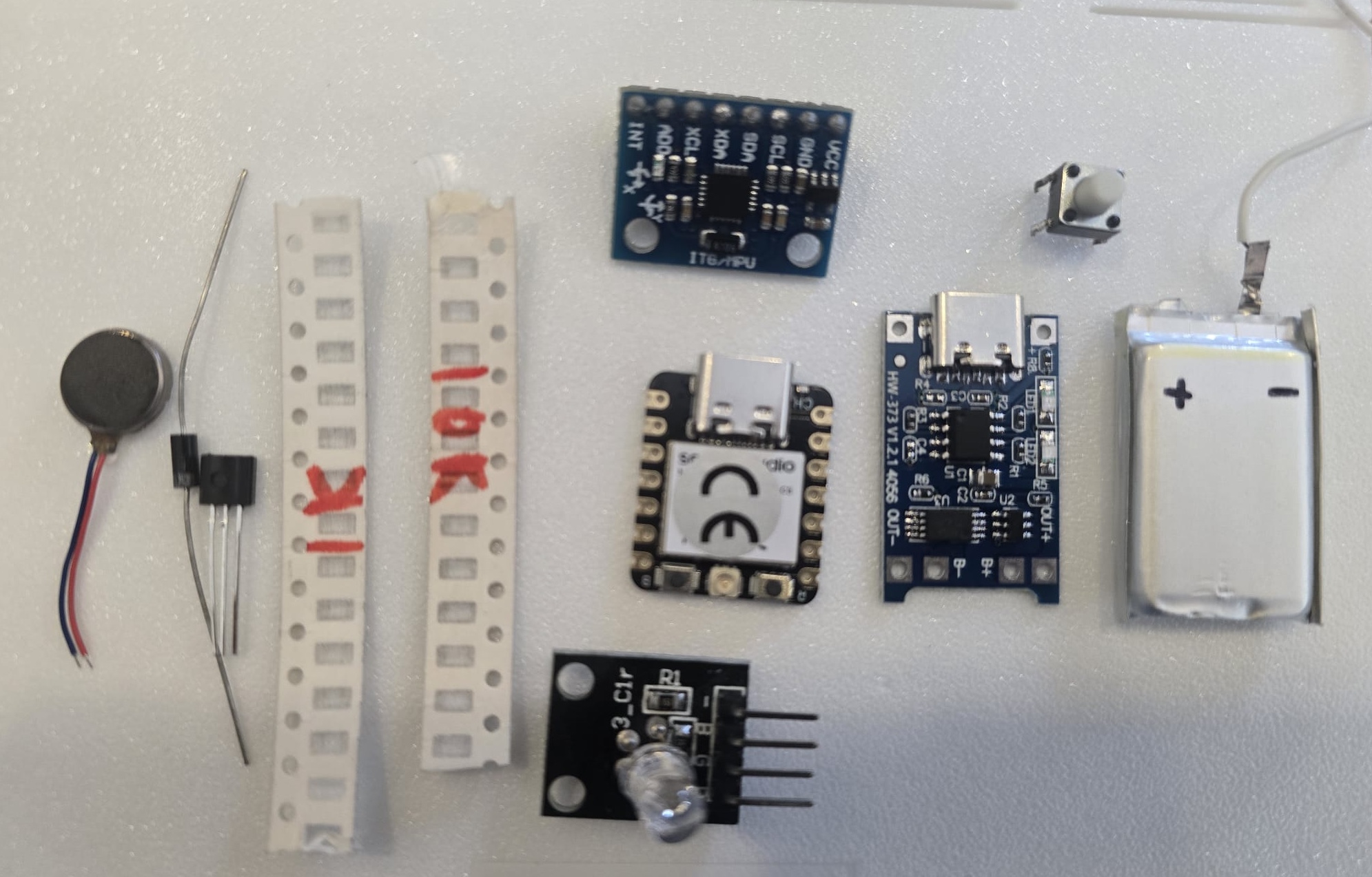
I selected the following items as the main components — the full testing for each was done in the previous weeks:
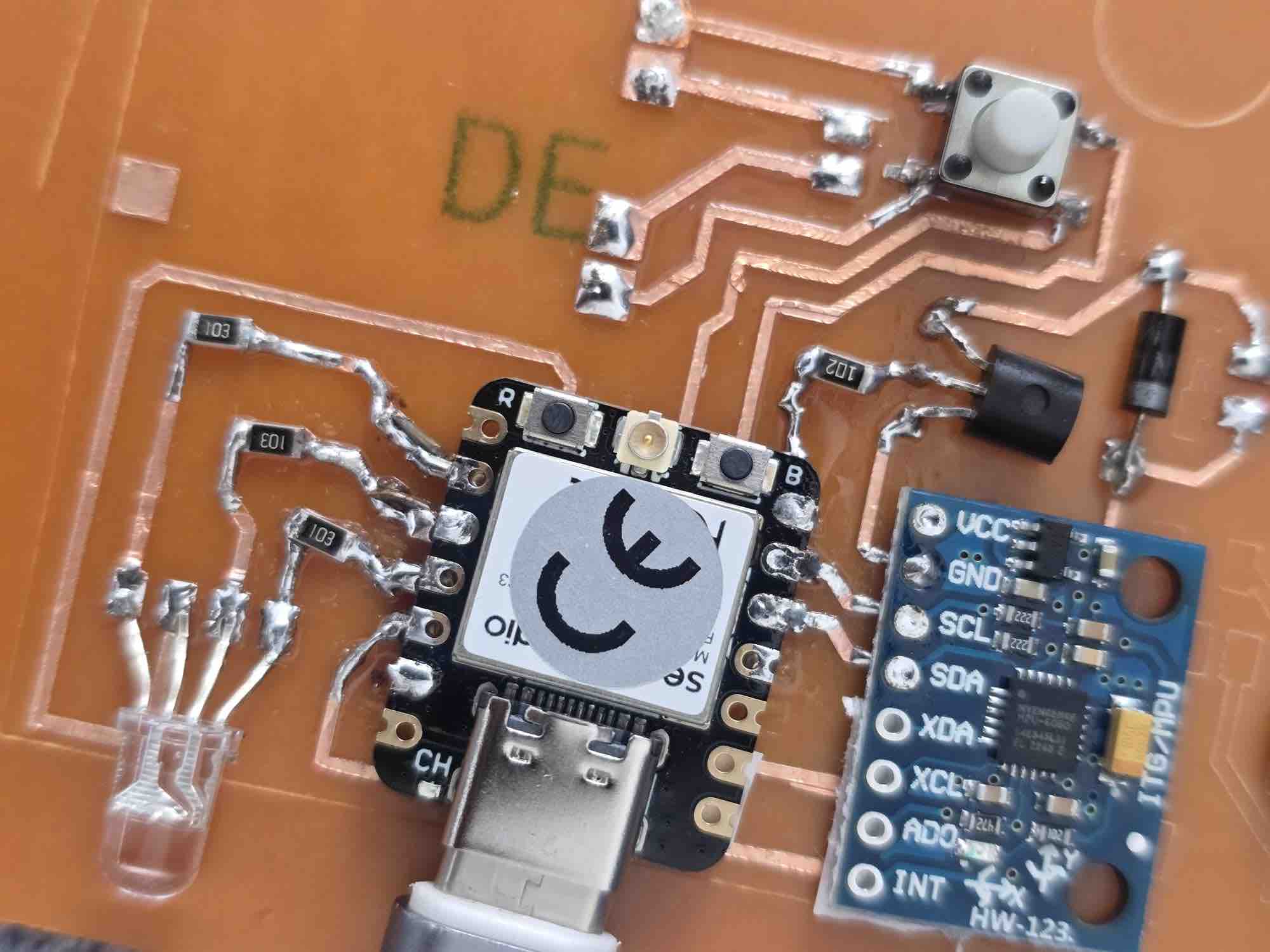
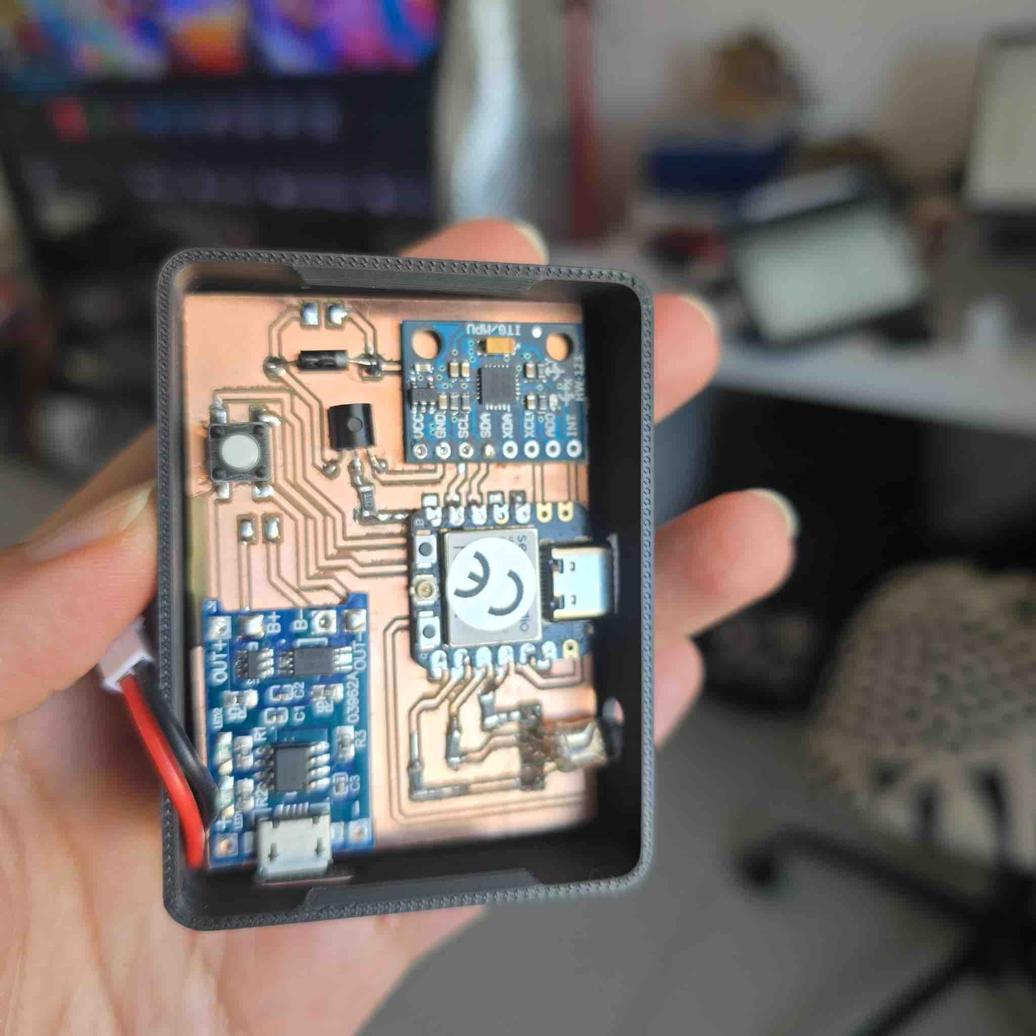
MPU6050 (GY-521) gyroscope to read the angle of the shoulder (detailed in Input Devices week), a vibration motor (detailed in Output Devices week), a 1K resistor + 2N2222A transistor + 1N4001 diode, an RGB LED (common anode) with three 10K resistors, and a TP4056 micro-USB charging module connected to a lithium battery and wired through a button. Electronics Architecture
Component
Function
Interface
Voltage
Notes
ESP32 Microcontroller
Main processing unit for sensor data and feedback logic
Isolates the motor's current draw from the ESP32-C3 pin
1N4001 diode
Flyback / freewheeling diode across the motor
Parallel to motor (cathode → V+)
—
Suppresses inductive back-EMF when the motor switches off
1 KΩ resistor
Base current limiter for the 2N2222A driving the vibration motor
In series with transistor base
—
1× per clip (vibration-motor module)
10 KΩ resistors (×3)
Current limiters for the R, G, and B channels of the RGB LED
In series with each LED leg → GPIO 8 / 9 / 20
3.3 V
3× per clip — one per colour channel; common-anode means logic 0 = ON
RGB LED (common anode)
Visual feedback indicator (state, BLE pairing, posture alert)
3× GPIO (PWM-capable) via 10 KΩ each
3.3 V
Common anode to 3.3 V; cathodes to GPIO through 10 KΩ resistors
Tactile push button
Power on/off and pairing toggle
GPIO with internal pull-up
3.3 V
One per clip; debounced in firmware
Rechargeable LiPo Battery
Portable power source
Direct Power
3.7V
Enables wearable device operation
Charging Module
Battery charging and protection circuit
Power Management
5V Input
Allows safe USB charging
02|02| PCB
Based on the skills and experience I built up over the previous weeks, this was the workflow for my PCB development.
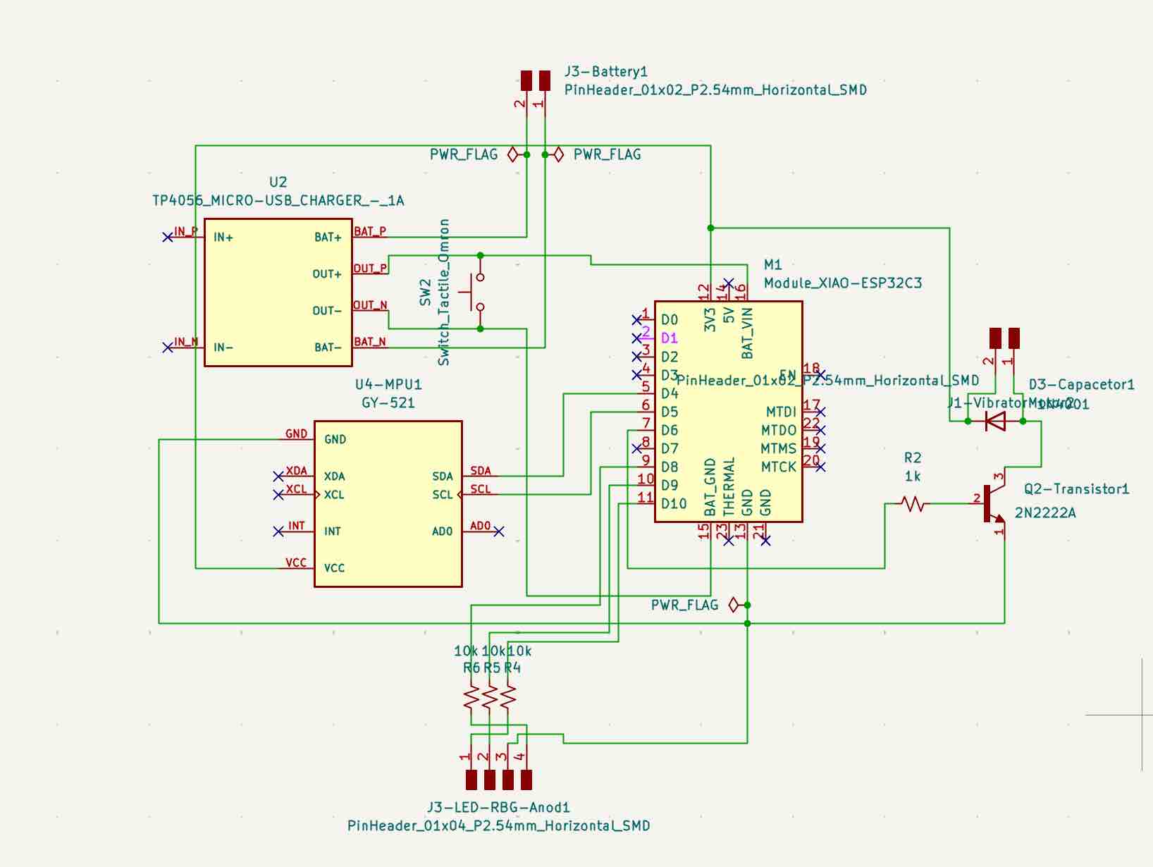
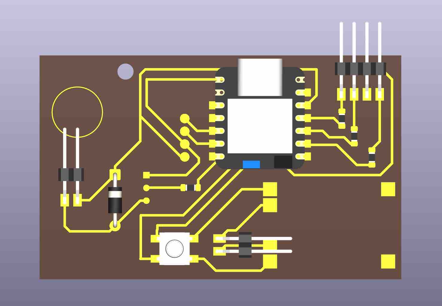
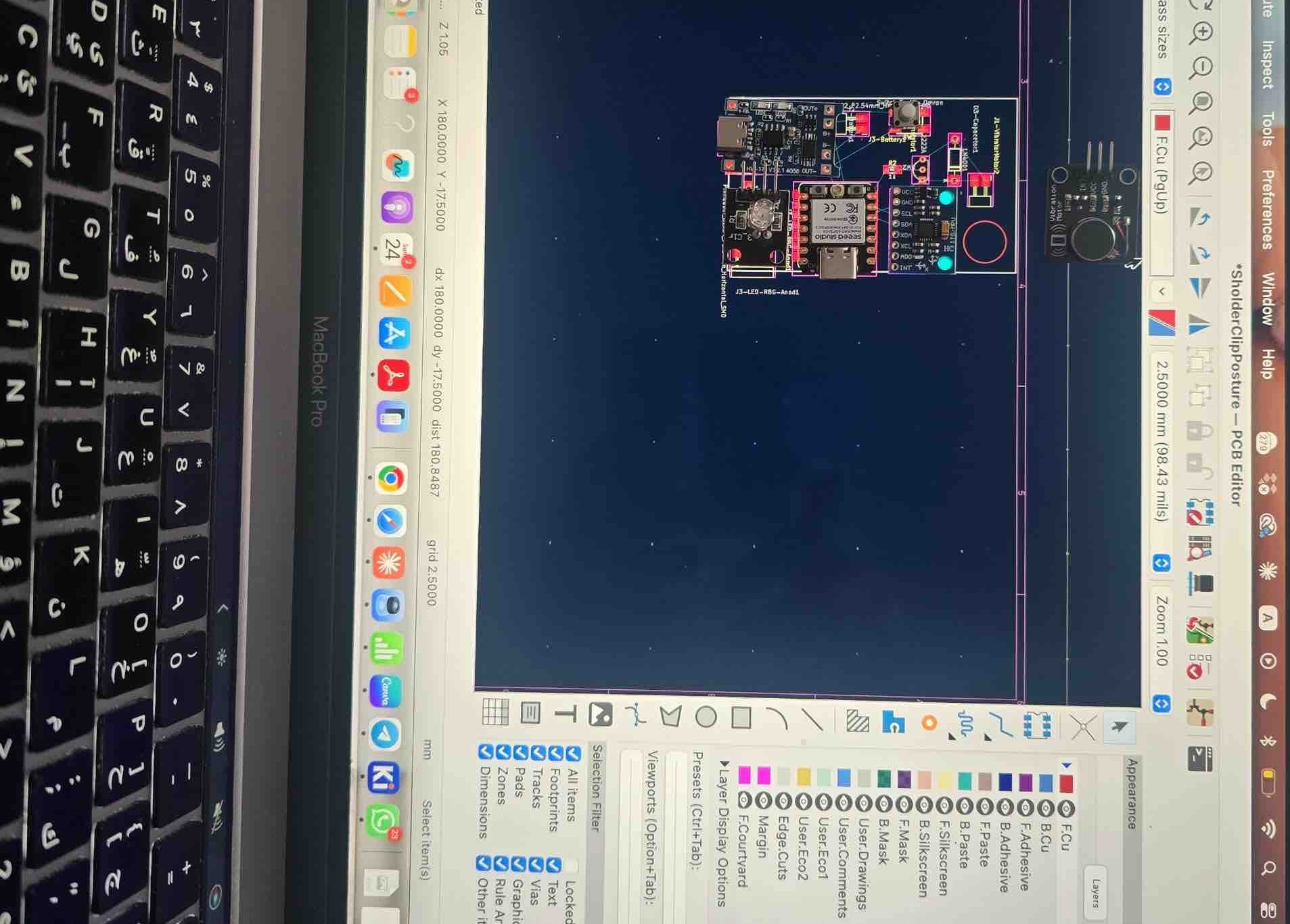
02|02|01| PCB Design
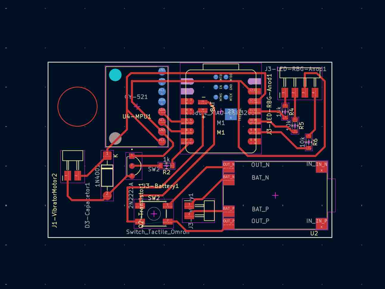
Create a new project in KiCad → open the schematic editor → add the components and make sure each has a footprint → if not, download the files and add them to the library → connect the ports and mark the unused ones as "no connect" → run the Electrical Rules Check (ERC) → solve errors and make sure I understand the warnings → switch to the PCB Editor and import the components with their connections → customize the track width to 0.5 mm, which gave me the best results when cutting the PCB (see Week 08 for details) → rearrange the components → change the unconnected SMD pads' copper layer to B.Cu to avoid affecting the tracks → route the tracks → run the Design Rules Check (DRC) → fix any errors and review the warnings → align the components on my laptop screen to match the spacing on the PCB — this is critical when using components that aren't available in the KiCad footprint libraries → plot and export the Gerber file after 4 versions and tweaks for better results, especially given the shortage of PCB stock — I had to fit this PCB into a 71 mm length design.
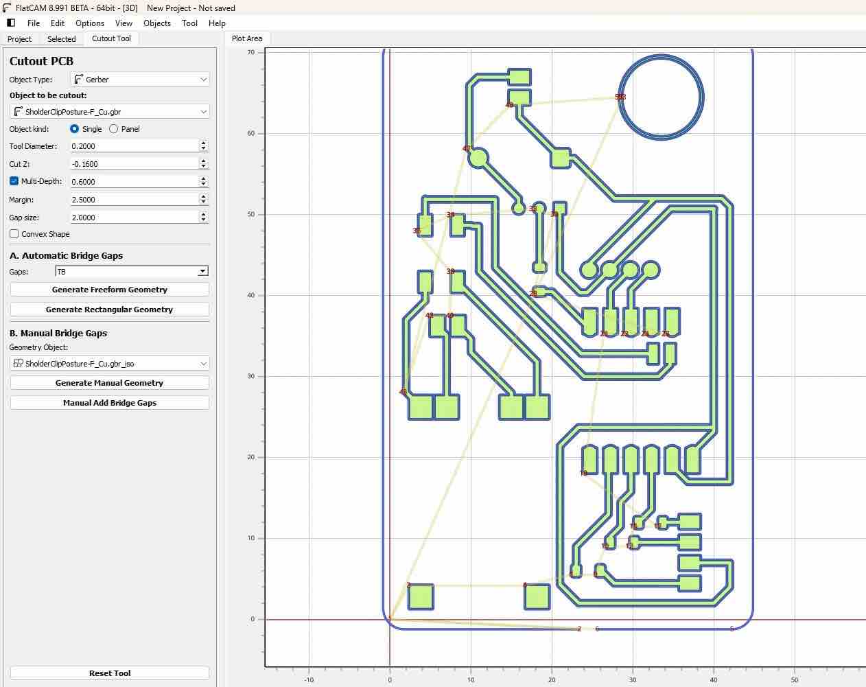
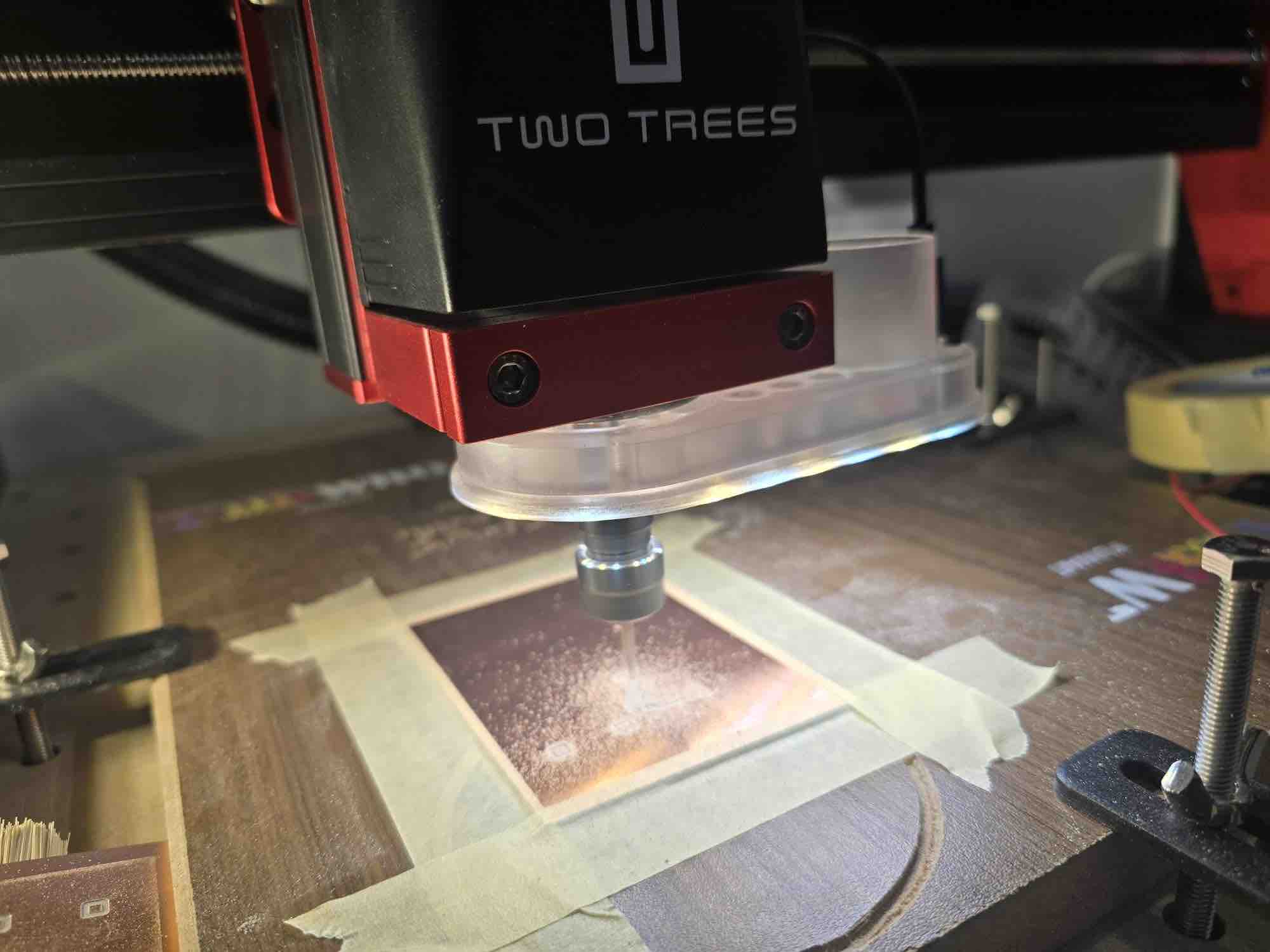
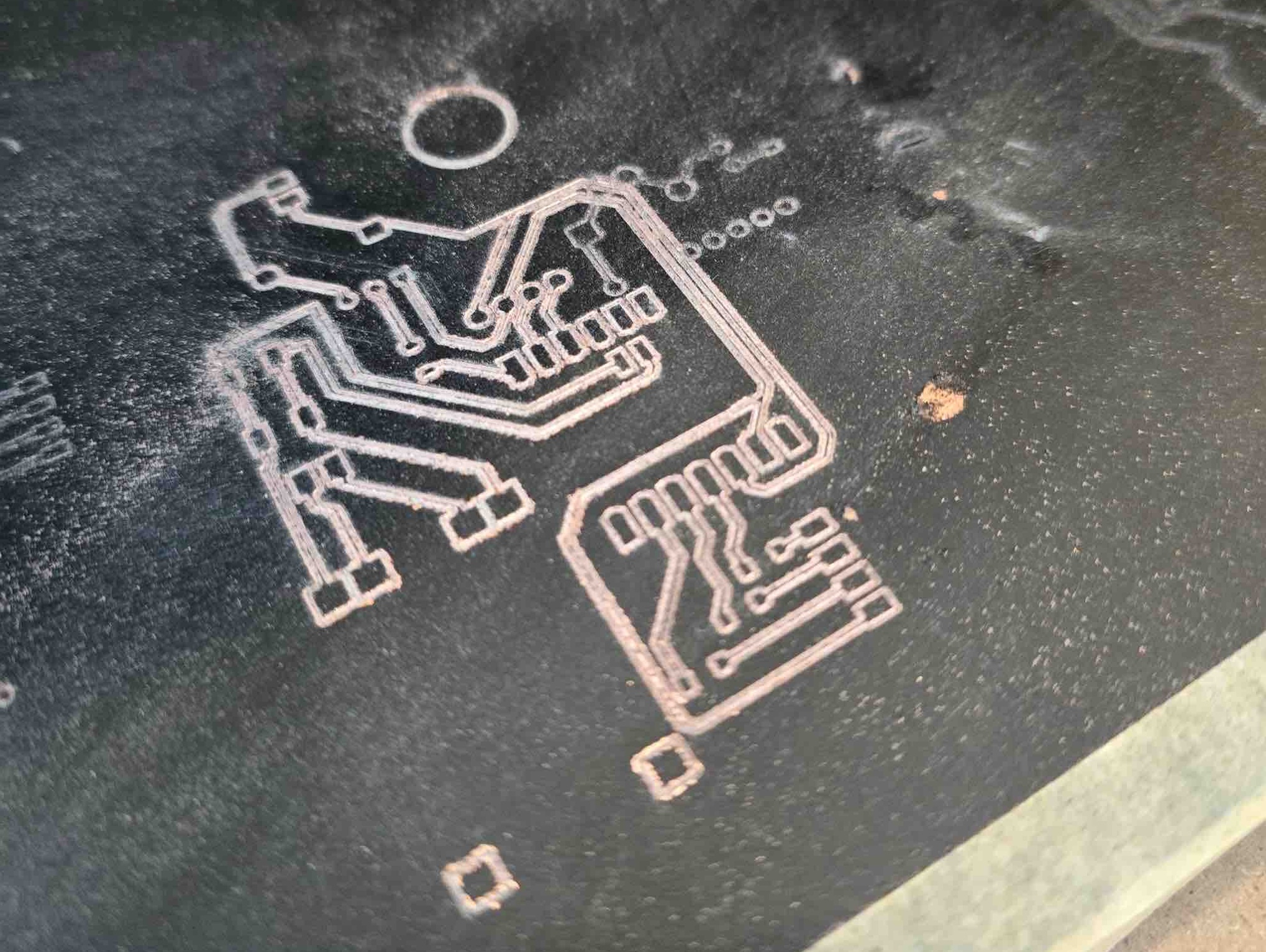
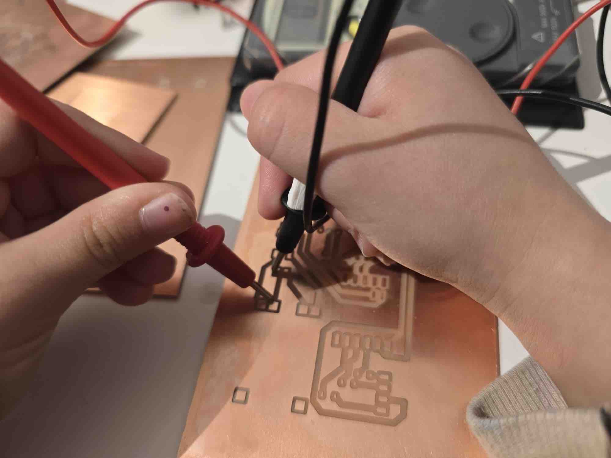
02|02|02| PCB Milling
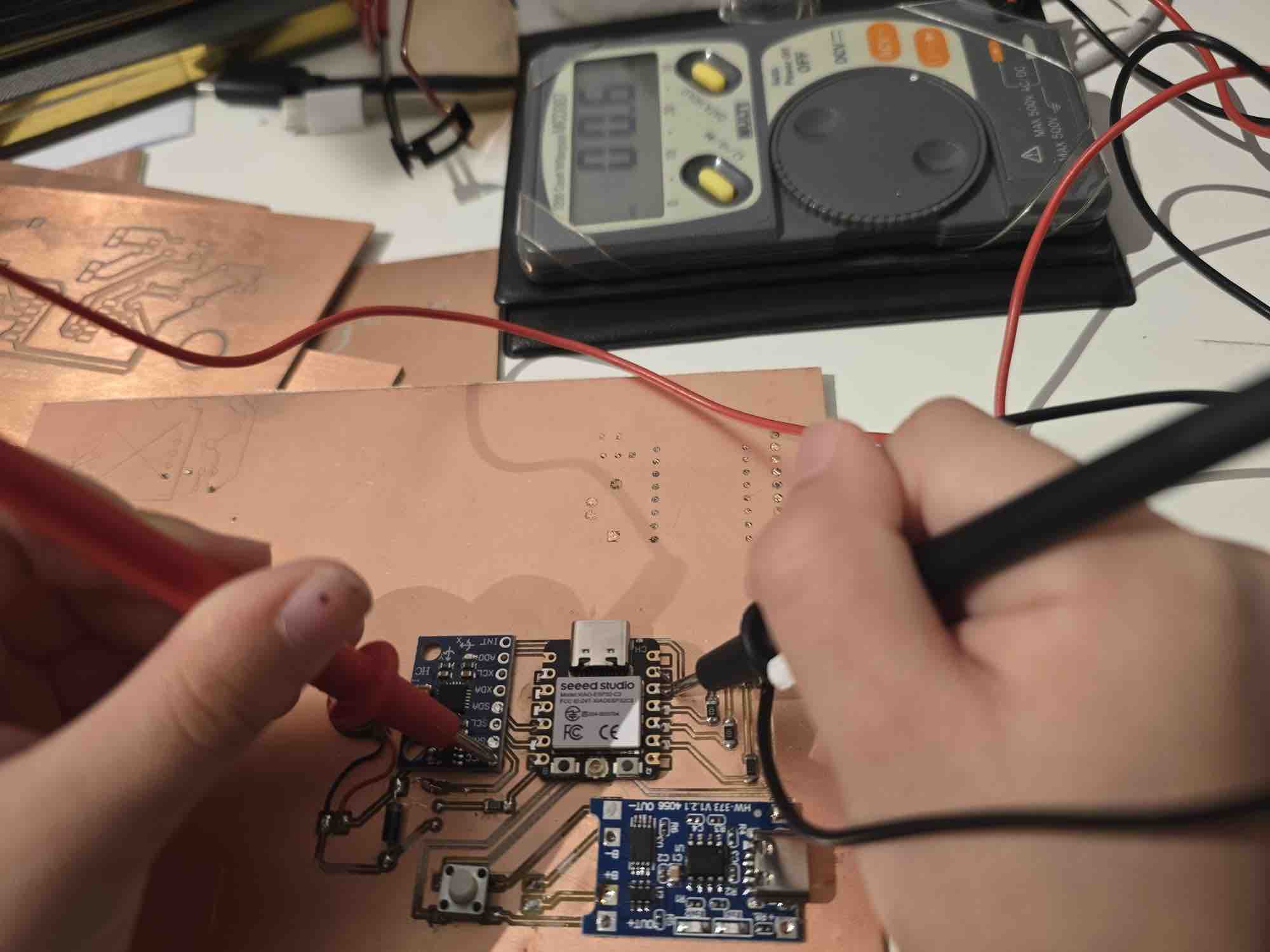
Import the Gerber file into FlatCAM → align the PCB design to the (0,0) origin → add an external buffer of 0.4 mm → make sure the tracks and routes are clear and don't overlap with the cutting routes or buffer → export the G-code file → in Easel, import the file → set up the CNC as documented in Week 08 → start milling → use a multimeter to check the routes
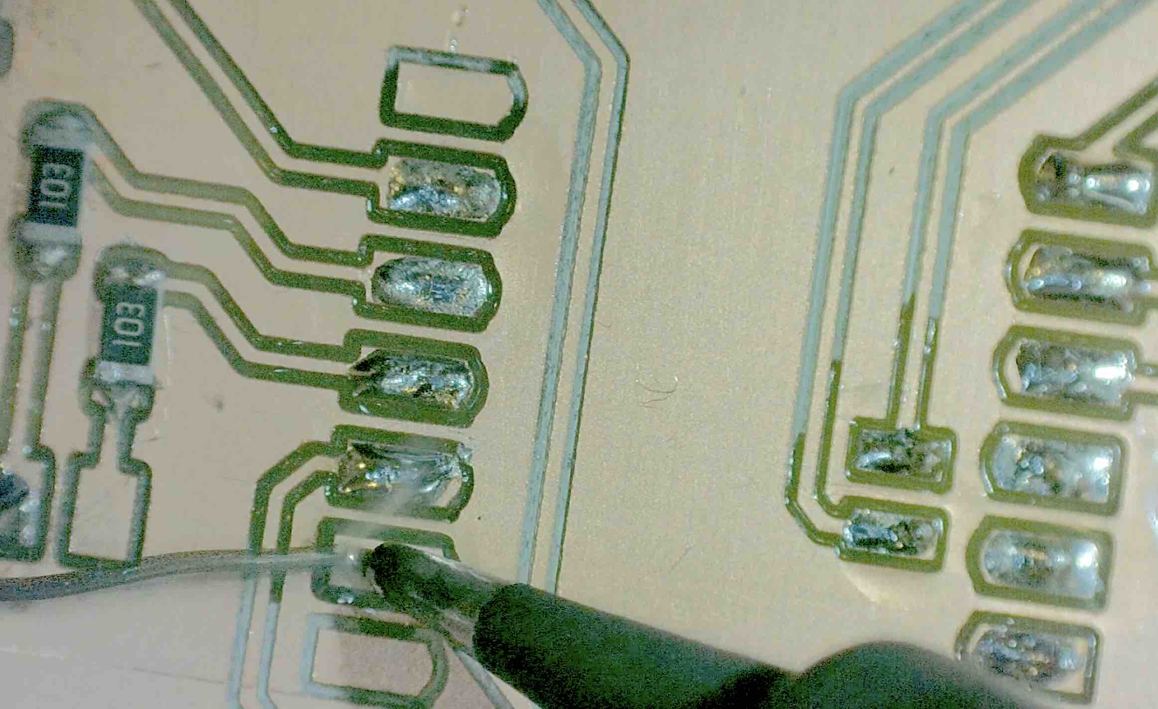
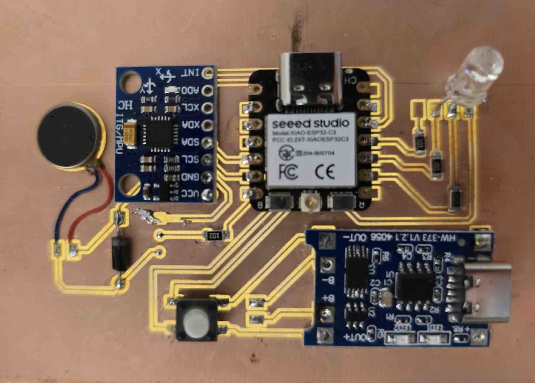
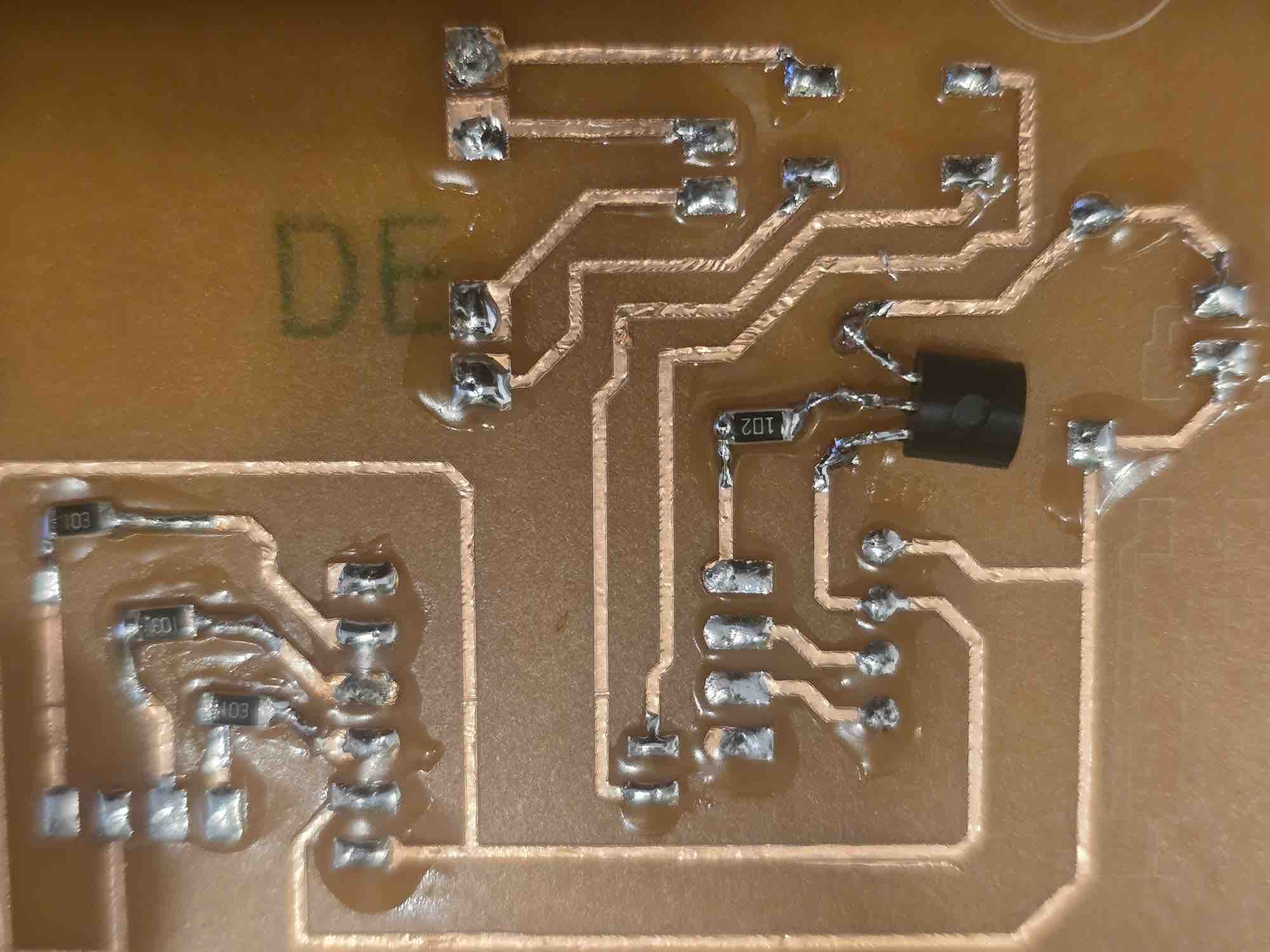
02|02|03| Soldering the components
I prepared my soldering station, keeping the main components close to me and following safety measures → I used the microscope to get better visibility on the PCB and the SMD components I'm using → first I applied solder flux paste (RMA-223) on the pads → I added a little solder (Flux Solder 0.8mm/100g, ProsKit 8PK-033A-L) on the pads → make sure the components' legs match the spaces on the PCB → I review my PCB design and confirm the correct ends are matched to avoid short circuits; I try to keep the legs fixed in place → heat the previously soldered pads → once I feel the component has settled onto its pads, I remove the solder tip → repeat this process until all the parts are soldered and fixed → I run a multimeter test to confirm which routes are connected and which are isolated → Done.
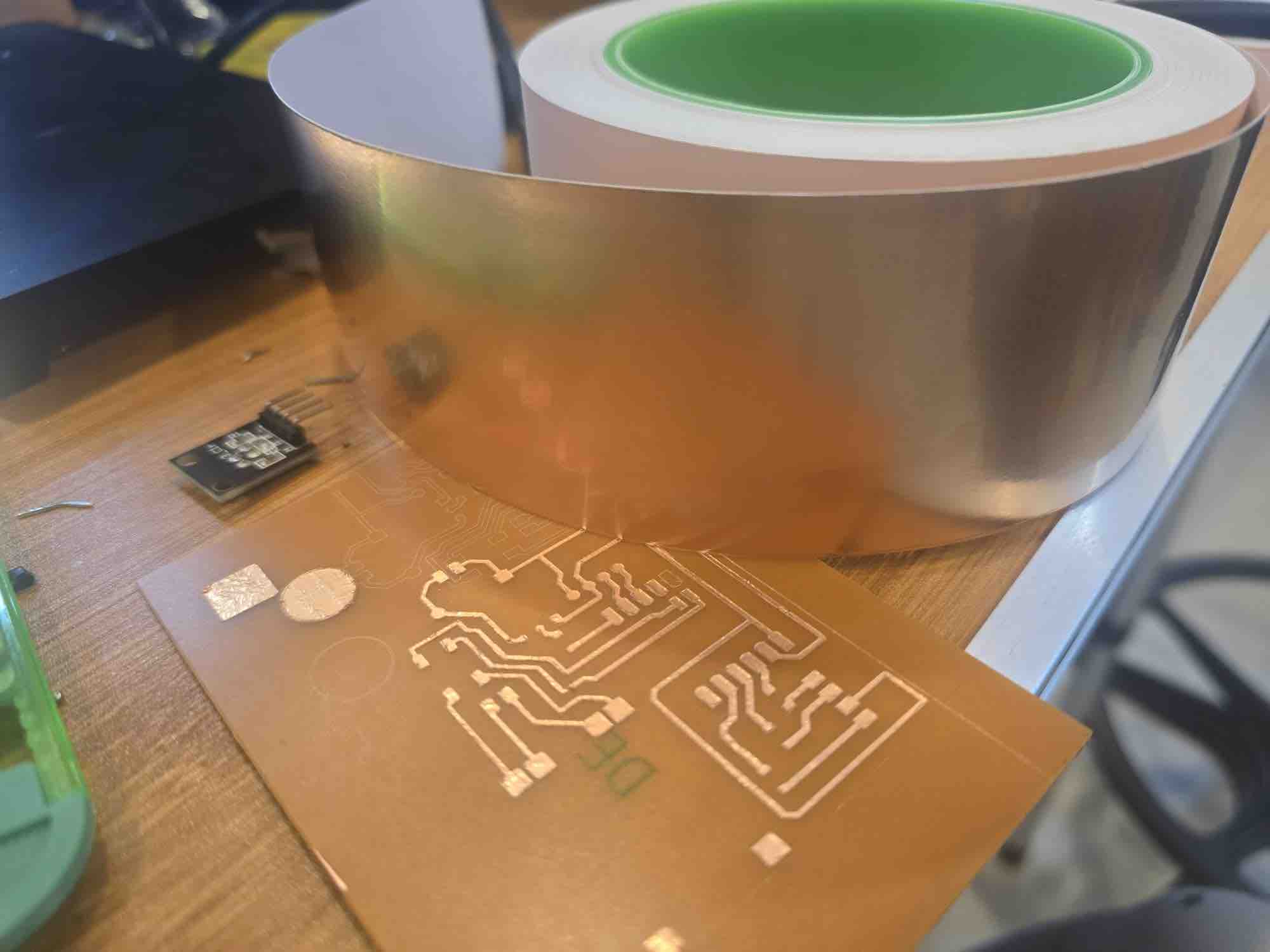
02|02|04| PCB Vinyl Cut
I ran out of PCB stock when I reached this far, so I had to create my second clip PCB using the vinyl cutter and copper tape. The complete process is documented in Week 10 — Output Devices. This is the workflow I followed: from KiCad I plotted the PCB design as an SVG file → open the file in Adobe Illustrator → select all the drawn strokes and expand them to shapes → union all the shapes → export as SVG and import it into the cutter software → make sure the complete circuit fits inside the cutting area → stick the copper tape carefully on a hard surface (the back of a PCB I'd already used) → attach the hard board on the cutting mat → align the cutter head → run a test cut → initiate the cut → carefully remove the unwanted copper tape → done — the vinyl-cut circuit is ready for attaching components.
03| Coding and Programing
03|01| Microcontroller Programing
03|01|01| Sensors Code Setup
I'm using the XIAO for the first time in this project — I had used the ESP32-C3 SuperMini in the previous assignments — and I also don't have full access to the lab. I'll be using Gemini as my paired-programming assistant in this phase. (AI usage audit report — to be added.)
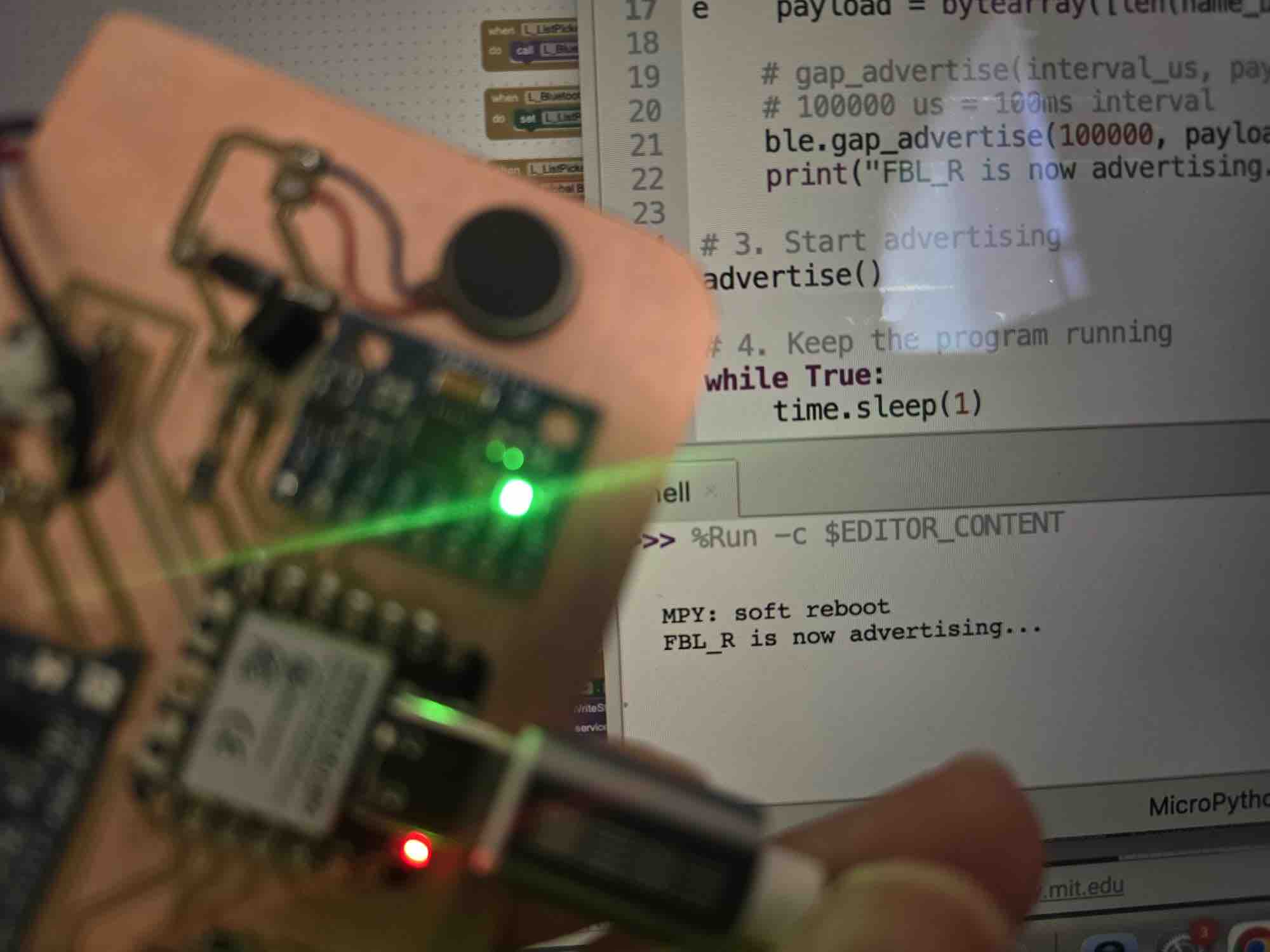
I selected Thonny IDE to start coding in MicroPython → I connected the XIAO via USB cable → first, set the microcontroller name to FBL_R and advertise it so it can be discovered by the interface app we will develop
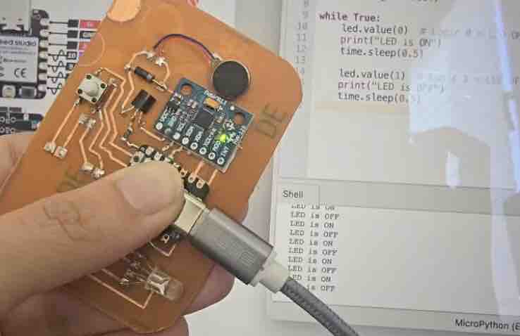
→ test the connection with each component → blink the LED first
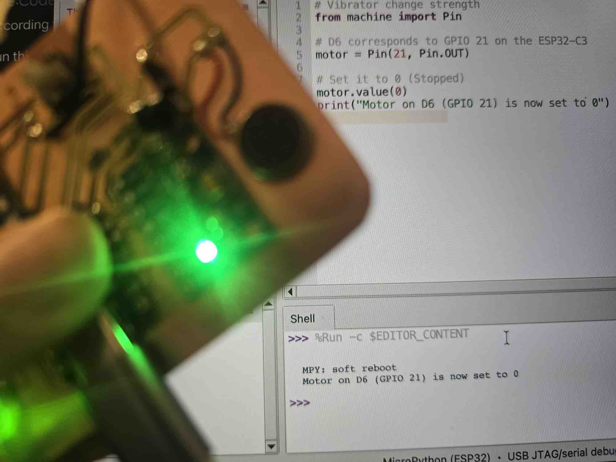
→ vary the vibration motor strength
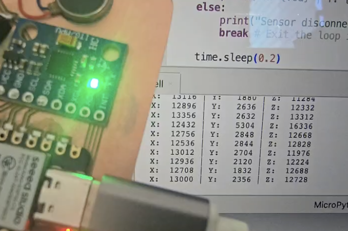
→ wake up the MPU sensor and read the X, Y, Z values
# Advertise device Bluetooth Name
import bluetooth
import time

# 1. Initialize BLE
ble = bluetooth.BLE()
ble.active(True)

# 2. Define the name
DEVICE_NAME = "FBL_R"

def advertise():
    # BLE Advertisement format: [Length, Type, Data]
    # Type 0x09 is the 'Complete Local Name'
    name_bytes = DEVICE_NAME.encode('utf-8')
    # Payload = [Len of name + 1, Type 0x09, The Name]
    payload = bytearray([len(name_bytes) + 1, 0x09]) + name_bytes

    # gap_advertise(interval_us, payload)
    # 100000 us = 100ms interval
    ble.gap_advertise(100000, payload)
    print("FBL_R is now advertising...")

# 3. Start advertising
advertise()

# 4. Keep the program running
while True:
    time.sleep(1)
# LED light blinking

from machine import Pin
import time

# Replace 'X' with the GPIO number from your PCB design
led = Pin(X, Pin.OUT)

while True:
    led.value(0)  # Logic 0 = LED ON (Common Anode)
    print("LED is ON")
    time.sleep(0.5)

    led.value(1)  # Logic 1 = LED OFF
    print("LED is OFF")
    time.sleep(0.5)
# Vibrator change strength
from machine import Pin

# D6 corresponds to GPIO 21 on the ESP32-C3
motor = Pin(21, Pin.OUT)

# Set it to 0 (Stopped)
motor.value(0)
print("Motor on D6 (GPIO 21) is now set to 0")
# MPU sensor and reading
import machine
import time
import struct

# Initialize I2C
i2c = machine.I2C(0, sda=machine.Pin(6), scl=machine.Pin(7))
addr = 0x68

# IMPORTANT: Wake up the MPU-6050 inside this script
try:
    i2c.writeto_mem(addr, 0x6B, b'\x00')
    print("MPU-6050 Woken Up Successfully")
except:
    print("Could not find sensor. Check wires!")

def read_accel():
    try:
        # Read 6 bytes starting from 0x3B
        data = i2c.readfrom_mem(addr, 0x3B, 6)
        # Unpack high and low bytes into 3 signed integers (x, y, z)
        return struct.unpack('>hhh', data)
    except:
        return None

while True:
    vals = read_accel()
    if vals:
        ax, ay, az = vals
        print("X: {:6d} | Y: {:6d} | Z: {:6d}".format(ax, ay, az))
    else:
        print("Sensor disconnected!")
        break # Exit the loop if the sensor is lost

    time.sleep(0.2)
03|01|02| Functional Code on the clip
Gemini was my main source of code for this part — , and a complete audit file is available here. After many iterations, questions, and clarifications, uploaded to both microcontrollers — with one thing different ("Name: FAB_L" vs "Name: FAB_R") to identify the two clips when connected.
Prompt to Gemini: OK, today we'll start coding the complete code for the microcontroller, then I'll start linking it to the app. Let's start with the microcontroller first: advertise the name so it can be discovered on Bluetooth, set X/Y/Z for the calibration, and define the function for when the angle changes by 10% for a duration of 3 minutes. Keep in mind the angle and duration should be variables defined by the user through the app. If the movement is beyond the defined angles, the vibration motor should start working and the LED should start blinking. Once it's back in the predefined calibrated position, the vibrator should stop and the LED becomes stable. (Verbatim prompt — kept as sent.)
import machine
import bluetooth
import time
import struct
from machine import Pin, PWM, ADC
# ==============================================================================
# 0. TWIN-NODE SIDE SELECTION (CHANGE THIS PER NODE BEFORE FLASHING!)
# ==============================================================================
CLIP_SIDE = "FBL_R" # Set to "FBL_L" for left clip, "FBL_R" for right clip
# ==============================================================================
# 1. HARDWARE CONFIGURATION
# ==============================================================================
i2c = machine.I2C(0, sda=machine.Pin(6), scl=machine.Pin(7), freq=400000)
MPU_ADDR = 0x68
# Indicators (Common Anode LEDs: 1=OFF, 0=ON)
led_red = machine.Pin(10, machine.Pin.OUT) # D10
led_green = machine.Pin(9, machine.Pin.OUT) # D9
led_blue = machine.Pin(8, machine.Pin.OUT) # D8
# Actuator: Initialize Motor Pin (GPIO 21) as PWM at 1000Hz
motor_pwm = PWM(Pin(21))
motor_pwm.freq(1000)
# Battery Telemetry: Initialize ADC on Pin A0 (GPIO 2)
battery_adc = ADC(Pin(2))
battery_adc.atten(ADC.ATTN_11DB)
# Safe initial hardware baselines
motor_pwm.duty(0)
led_red.value(1)
led_green.value(1)
led_blue.value(1)
# ==============================================================================
# 2. VARIABLE REGISTRY (Dynamic Targets via BLE App)
# ==============================================================================
ALLOWED_DRIFT = 0.25 # Default 25% structural drift allowance
ALERT_DURATION_THRESHOLD = 5 # Default 5-second test window delay
MOTOR_STRENGTH = 75 # Default 75% vibration strength
BATTERY_PERC = 100 # Calculated live battery scale
# Calibration Targets
cali_x, cali_y, cali_z = 0.0, 0.0, 0.0
is_calibrated = False
trigger_calibration = False # Volatile flag managed by incoming App requests
# Time Registries
slump_start_time = None
last_blink_time = time.ticks_ms()
last_battery_check = 0
led_toggle_state = False
# ==============================================================================
# 3. BLE STACK & UUID REGISTRATION (Fixed Initialization Order)
# ==============================================================================
_BLE_IRQ_CENTRAL_WRITE = 3
# 1. Instantiate the physical hardware BLE object FIRST
ble = bluetooth.BLE()
ble.active(True)
# 2. Define the universally unique profiles
SERVICE_UUID = bluetooth.UUID("6E400001-B5A3-F393-E0A9-E50E24DCCA9E")
CONFIG_CHAR_UUID = bluetooth.UUID("6E400002-B5A3-F393-E0A9-E50E24DCCA9E")
BATTERY_CHAR_UUID = bluetooth.UUID("6E400003-B5A3-F393-E0A9-E50E24DCCA9E")
# 3. Register local services database
SERVICES_REGISTRY = (
SERVICE_UUID,
(
(CONFIG_CHAR_UUID, bluetooth.FLAG_WRITE),
(BATTERY_CHAR_UUID, bluetooth.FLAG_READ | bluetooth.FLAG_NOTIFY),
),
)
((config_handle, battery_handle),) = ble.gatts_register_services((SERVICES_REGISTRY,))
# 4. Define the interrupt packet listener
def ble_interrupt_handler(event, data):
global ALLOWED_DRIFT, ALERT_DURATION_THRESHOLD, MOTOR_STRENGTH, trigger_calibration
if event == _BLE_IRQ_CENTRAL_WRITE:
conn_handle, value_handle = data
if value_handle == config_handle:
raw_packet = ble.gatts_read(config_handle).decode('utf-8').strip()
print("Received BLE Payload:", raw_packet)
try:
if raw_packet == "CAL":
trigger_calibration = True
elif raw_packet.startswith("STR:"):
MOTOR_STRENGTH = int(raw_packet.split(":")[1])
elif raw_packet.startswith("DEL:"):
ALERT_DURATION_THRESHOLD = int(raw_packet.split(":")[1])
elif raw_packet.startswith("ANG:"):
ALLOWED_DRIFT = float(raw_packet.split(":")[1])
except Exception as parse_error:
print("Failed to map incoming packet structure:", parse_error)
ble.irq(ble_interrupt_handler)
# 5. Define the advertising function LAST (Now it safely knows what 'ble' is!)
def start_ble_advertising():
name_bytes = CLIP_SIDE.encode('utf-8')
payload = bytearray()
payload += bytearray([0x02, 0x01, 0x06]) # Phone Flags
payload += bytearray([len(name_bytes) + 1, 0x09]) + name_bytes # Local Name Header
ble.gap_advertise(100000, payload)
print("BLE Stack Online. Broadcasting Identity payload for '{}'.".format(CLIP_SIDE))
# ==============================================================================
# 4. SYSTEM PROCESSING UTILITIES
# ==============================================================================
def init_mpu():
try:
i2c.writeto_mem(MPU_ADDR, 0x6B, b'\x00')
time.sleep(0.1)
return True
except:
return False
def read_accel_g():
try:
data = i2c.readfrom_mem(MPU_ADDR, 0x3B, 6)
raw_x, raw_y, raw_z = struct.unpack('>hhh', data)
return raw_x / 16384.0, raw_y / 16384.0, raw_z / 16384.0
except:
return None
def update_battery_percentage():
global BATTERY_PERC
try:
raw_value = battery_adc.read()
pin_voltage = (raw_value / 4095.0) * 3.3
actual_battery_voltage = pin_voltage * 2
if actual_battery_voltage >= 4.2: BATTERY_PERC = 100
elif actual_battery_voltage <= 3.4: BATTERY_PERC = 0
else:
BATTERY_PERC = int(((actual_battery_voltage - 3.4) / (4.2 - 3.4)) * 100)
# Update our internal Bluetooth register memory with the new level
ble.gatts_write(battery_handle, struct.pack(' last_second_print:
print("Node locked. Recording vectors... {}s remaining.".format(10 - current_second))
last_second_print = current_second
led_blue.value(0 if led_blue.value() == 1 else 1)
vals = read_accel_g()
if vals:
sum_x += vals[0]
sum_y += vals[1]
sum_z += vals[2]
samples_taken += 1
time.sleep(0.02)
if samples_taken > 0:
cali_x = sum_x / samples_taken
cali_y = sum_y / samples_taken
cali_z = sum_z / samples_taken
is_calibrated = True
trigger_calibration = False # Reset flag
led_blue.value(1)
led_green.value(0)
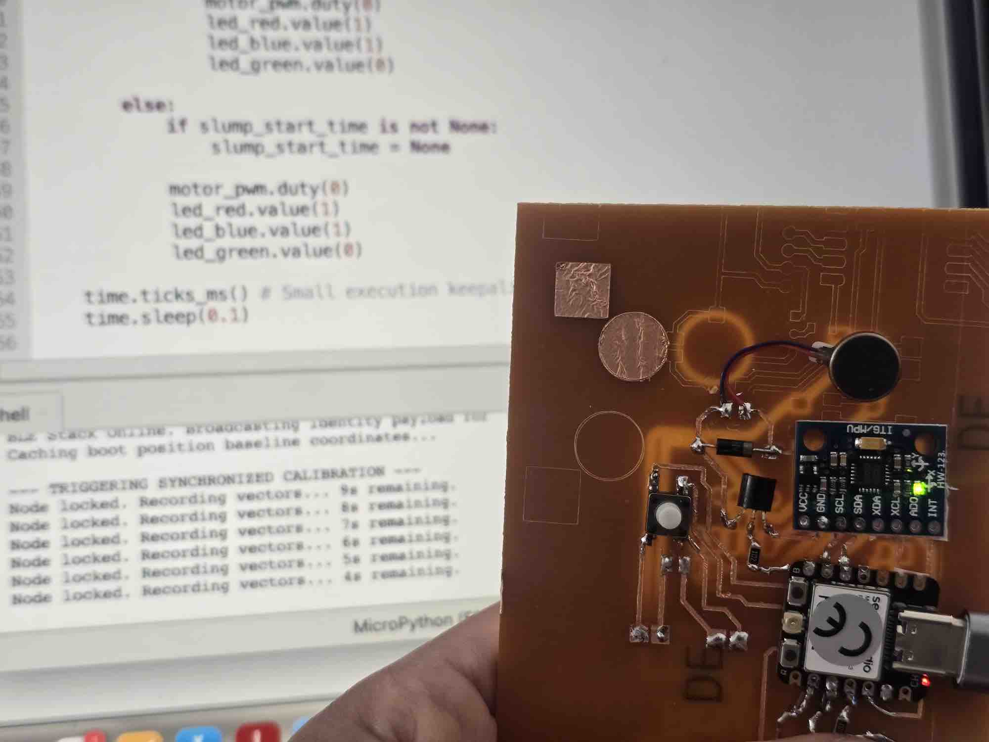
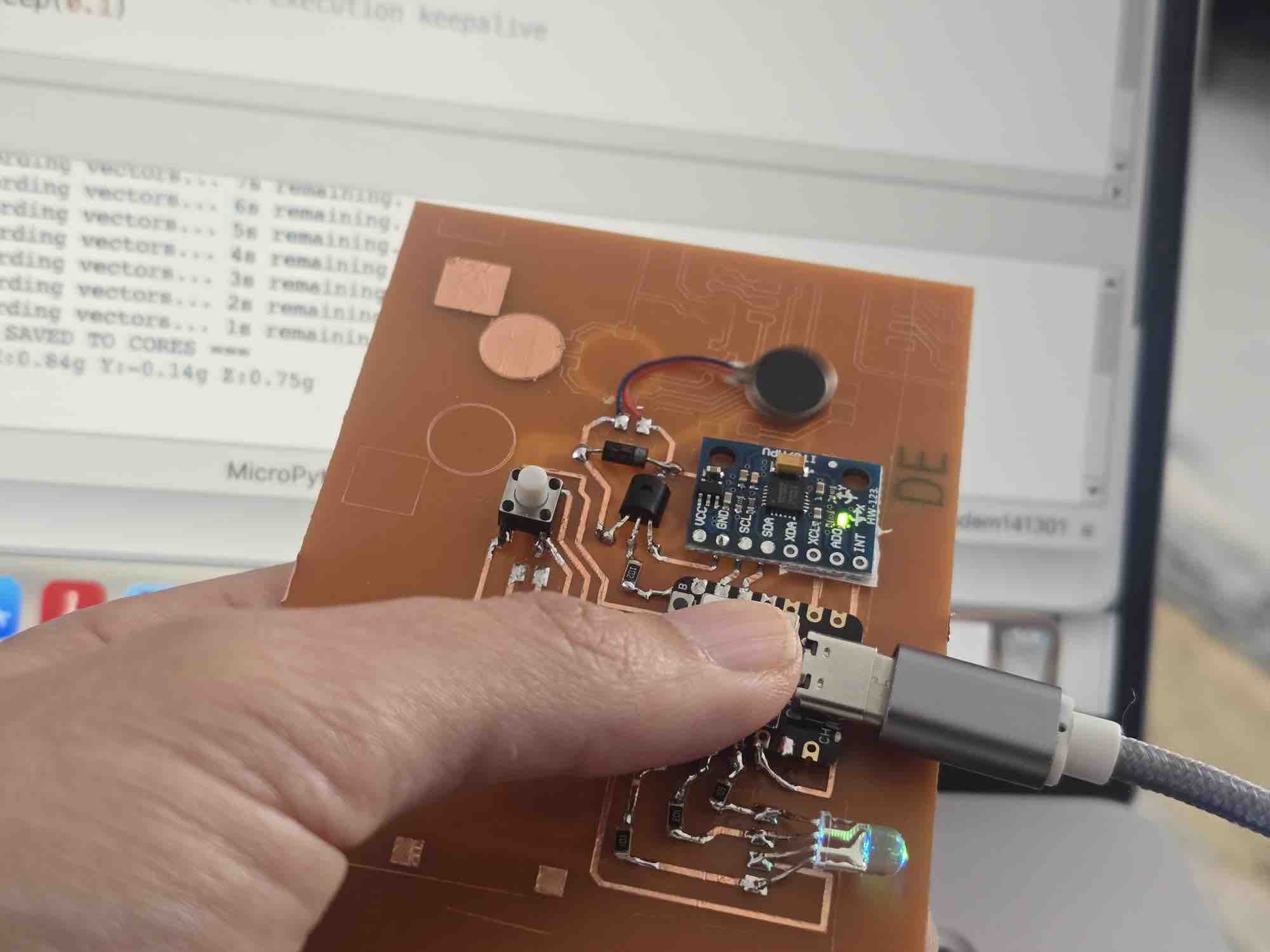
print("=== BASELINE DATA SAVED TO CORES ===")
print("Baseline Locked: X:{:.2f}g Y:{:.2f}g Z:{:.2f}g\n".format(cali_x, cali_y, cali_z))
else:
print("Error: Calibration sample collection failed.")
# ==============================================================================
# 5. INITIALIZATION RUNTIME
# ==============================================================================
start_ble_advertising()
mpu_status = init_mpu()
update_battery_percentage()
if mpu_status:
# Initial quick baseline lock so the hardware functions out-of-the-box
print("Caching boot position baseline coordinates...")
run_calibration()
# ==============================================================================
# 6. RUNTIME DATA EVALUATION LOOP
# ==============================================================================
while True:
if not mpu_status:
led_red.value(0)
time.sleep(0.5)
continue
# Execute over-the-air calibration interrupt immediately if app button was tapped
if trigger_calibration:
run_calibration()
# Track battery decay profiles every 5 seconds
if time.ticks_diff(time.ticks_ms(), last_battery_check) > 5000:
update_battery_percentage()
last_battery_check = time.ticks_ms()
current_vals = read_accel_g()
if current_vals:
cx, cy, cz = current_vals
diff_x = abs(cx - cali_x)
diff_y = abs(cy - cali_y)
diff_z = abs(cz - cali_z)
has_slumped = (diff_x > ALLOWED_DRIFT) or (diff_y > ALLOWED_DRIFT) or (diff_z > ALLOWED_DRIFT)
if has_slumped:
if slump_start_time is None:
slump_start_time = time.ticks_ms()
elapsed_seconds = time.ticks_diff(time.ticks_ms(), slump_start_time) / 1000
if elapsed_seconds >= ALERT_DURATION_THRESHOLD:
# Trigger haptics using dynamically updated strength limits
if MOTOR_STRENGTH > 0:
calculated_duty = int((MOTOR_STRENGTH / 100) * 1023)
motor_pwm.duty(calculated_duty)
# Rapid async flash alerting via blue light
if time.ticks_diff(time.ticks_ms(), last_blink_time) > 250:
led_toggle_state = not led_toggle_state
led_blue.value(0 if led_toggle_state else 1)
led_red.value(1)
led_green.value(1)
last_blink_time = time.ticks_ms()
else:
motor_pwm.duty(0)
led_red.value(1)
led_blue.value(1)
led_green.value(0)
else:
if slump_start_time is not None:
slump_start_time = None
motor_pwm.duty(0)
led_red.value(1)
led_blue.value(1)
led_green.value(0)
time.ticks_ms() # Small execution keepalive
time.sleep(0.1)
The logic, once a clip is powered on: → advertise the microcontroller name over Bluetooth → keep the vibration motor strength at 0 → RGB LED stays stable on green → on the app, the user taps "Start Calibration" → the clip starts a countdown from 10 sec down to 0 → the countdown is streamed back to the app for the user to see → when it reaches 0, the X / Y / Z baseline coordinates are saved on the clip → the user can now adjust vibration strength, delay, and accepted angle via sliders → when the clip deviates beyond the defined angle → an internal counter for the defined delay (default 5 sec) starts → if the angle hasn't returned to the acceptable threshold when the counter ends → the vibration motor starts at the defined strength → the RGB LED starts blinking.
03|02| App Interface
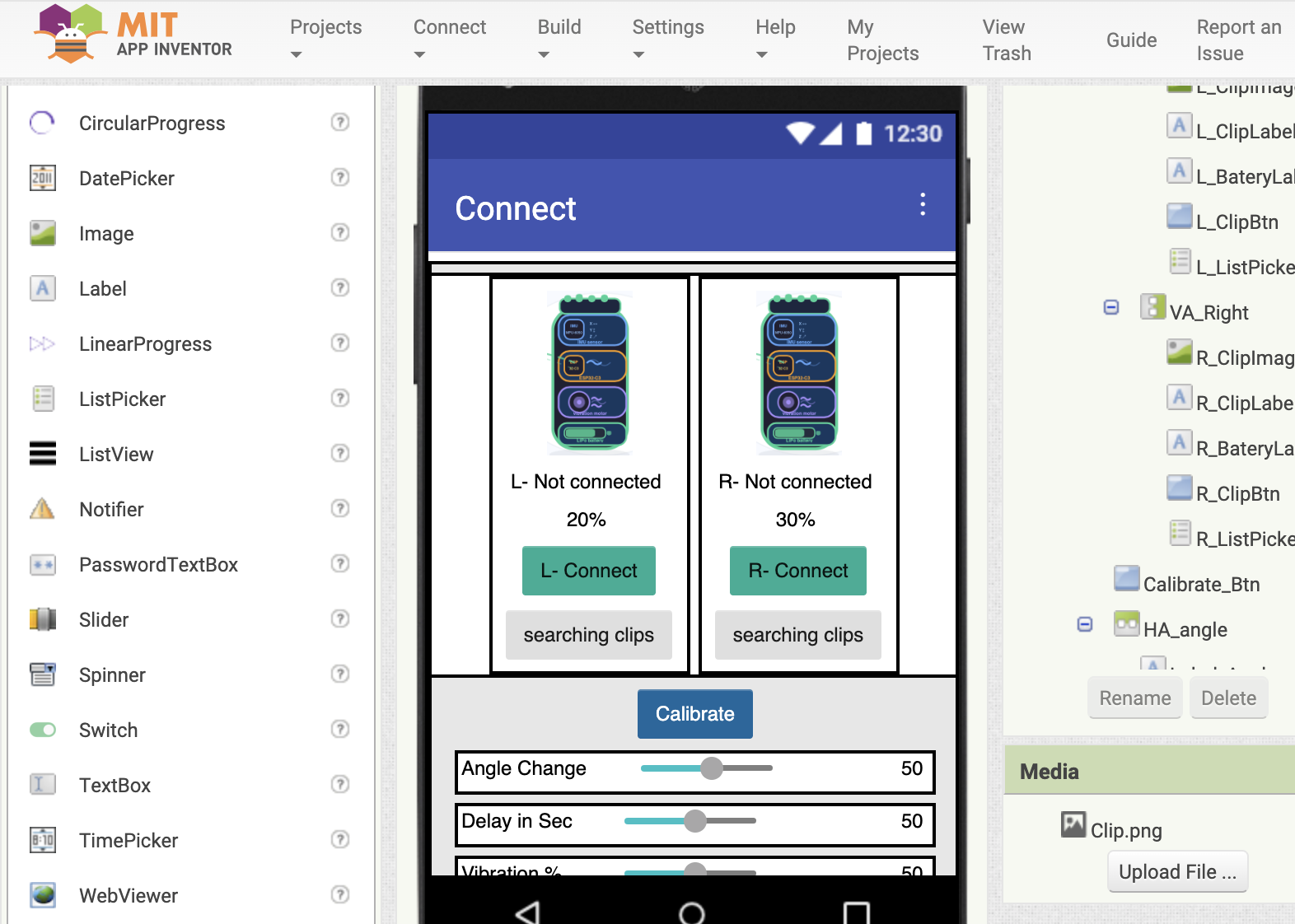
03|02|01| Design
I created my app using the MIT App Inventor platform which is documented in detail in Week 14. The first screen contains instructions on how to use the clips → I designed the two clips, left and right → I added a ListPicker to scan for Bluetooth devices → battery level indicators → a number of text labels to update the status of the connection → a Calibration button to set the acceptable degree within the threshold defined on the clips → sliders for the user's preferred acceptable angle threshold → the time delay before triggering the vibrator → vibration strength. I made sure all the components are clearly named as left/right — this is critical in the coding.
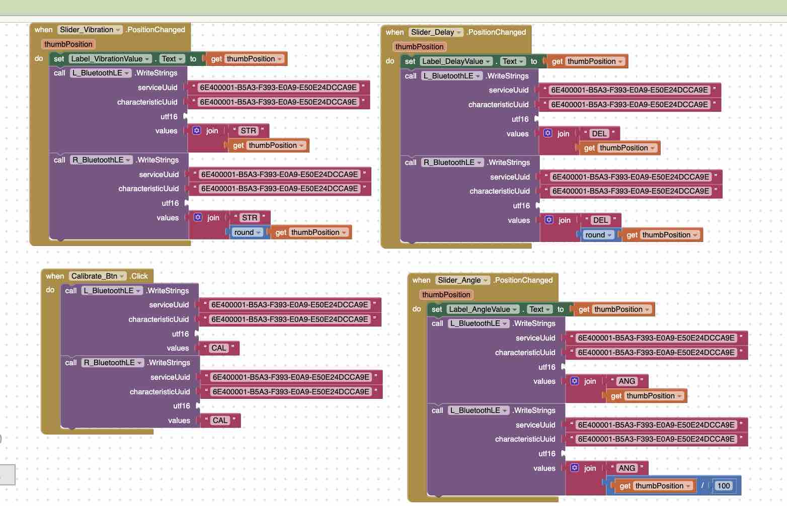
03|02|02| Block programming
App Inventor provides block-programming functionality that eases the use of syntax coding also documented in detail in Week 14. Here I duplicated the same commands for the left and right clips, calling on the Bluetooth connection and sending parameters to the ESP32-C3 microcontroller.
that started the discussion for developing the code for the integration between the clips and the app.
My prompt to Gemini: …before that, let's make sure the main logic is correct. OK, let's define the exact functionality between App Inventor and the microcontroller. We will have 1 app and 2 identical microcontroller clips — one left, one right. The app will first detect the clips, connect to them, (2) show the battery level, (3) initialize calibration when a button is clicked, (4) using the sliders on the app, the user can define 3 things on the slider: vibration strength, delay before the vibration and LED blinking start, and the angle for the "accepted threshold". The microcontroller should be on and working. (Verbatim prompt — kept as sent.)
03|03| Integrating clips with the App — architectural pivot
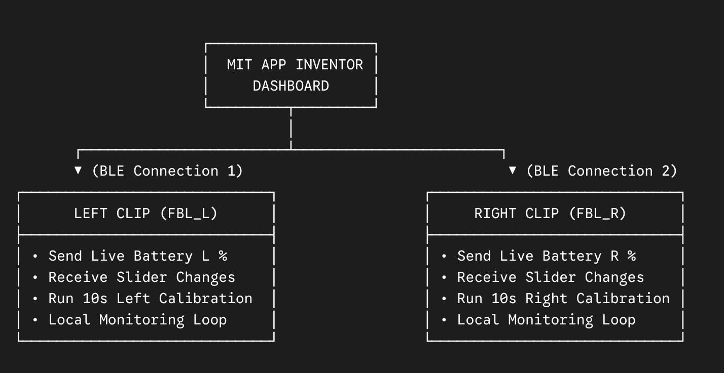
The original plan was for both clips to maintain their own BLE connection to the app. While developing it in Week 16 — Wildcard / IoT, I found that having the app juggle two parallel BLE sessions (each with its own pairing, calibration round-trip, and slider-threshold push) made the App Inventor block logic explode in complexity — every block had to duplicate for left vs right, every state variable had to track both, and the string-parsing on incoming BLE payloads had to demultiplex by source. I lost a full evening to that approach before pivoting.
New architecture (the one that shipped): the left clip is the gateway. The app maintains a single BLE link, only to the left clip. The left clip then forwards the relevant commands and thresholds to the right clip over ESP-NOW — a low-latency Espressif radio protocol designed exactly for device-to-device messaging without involving a phone or router.
Before — direct BLE to both clips
Phone (App Inventor app)
BLE ↘ BLE ↙
Left clip (FBL_L)Right clip (FBL_R)
Two BLE sessions in the app, all blocks duplicated L/R, payload demultiplexing in App Inventor.
After — gateway + ESP-NOW relay
Phone (App Inventor app)
BLE ↓
Left clip (FBL_L)gateway
ESP-NOW ↓
Right clip (FBL_R)
One BLE session, one source of truth, no demultiplexing. The right clip applies the same thresholds independently.
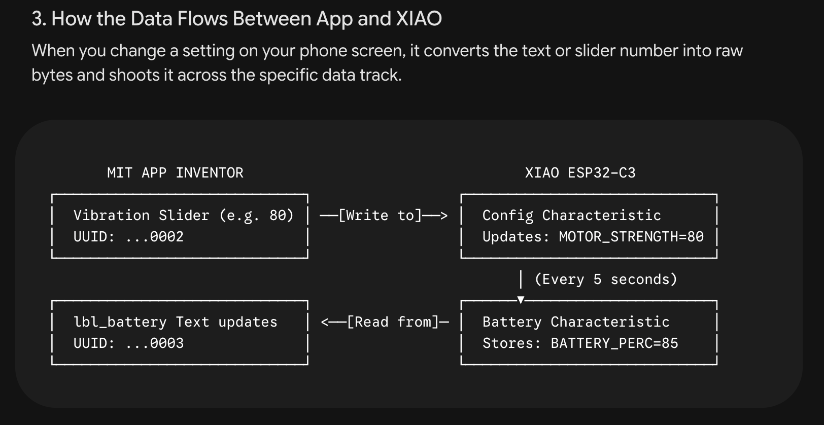
What gets forwarded: when the user updates a threshold on the app, the left clip receives the BLE write, applies it locally, and then re-broadcasts a small ESP-NOW packet containing {calibration_baseline, vibration_strength, delay, angle_threshold} to the right clip's MAC address. The right clip applies the same values and continues to run its own MPU6050 + alert loop independently — so each shoulder still corrects against its own baseline.
Why this works for the project specifically: shoulder-symmetry correction doesn't actually need the app to talk to both clips — it just needs both clips to enforce the same thresholds against their own readings. ESP-NOW is purpose-built for this kind of low-latency, peer-to-peer ESP32 chatter, so the right clip reacts to a threshold update within milliseconds of the left clip receiving it from the phone.
Trade-off accepted: the original plan also wanted a "persistent calibration" feature — clips remembering the last baseline so the user doesn't have to reconnect the app every time. That feature was dropped during this pivot (logged in the Reflection below) and moved to the next spiral, because adding persistent state on top of the gateway pattern would have added another layer of synchronisation I didn't have time for.
The full ESP-NOW prompt I gave Gemini, the App Inventor block changes, and the resulting firmware lives in Week 16.
03|04| Logic testing
Before attaching the battery to the boards, I connected them to a power bank using USB cables directly to the microcontroller → I launched the App Inventor Companion → scanned the QR code on my mobile → tapped the ListPicker to find the clips → selected the clips → the status of the clip on the app changed to "online / connected" → on tapping the Calibration button → a countdown starts for 10 seconds until the desired posture is fixed and saved on the microcontroller → the vibration strength, delay, and angle are also sent from the app to the microcontroller clips → when the posture is incorrect → the system counts for 5 sec → the blue LED turns on and the vibration starts → when the posture is restored → the vibration stops and the LED turns green.
04| Packaging
04|01| Clip Case
04|01|01| 3D design — FreeCAD
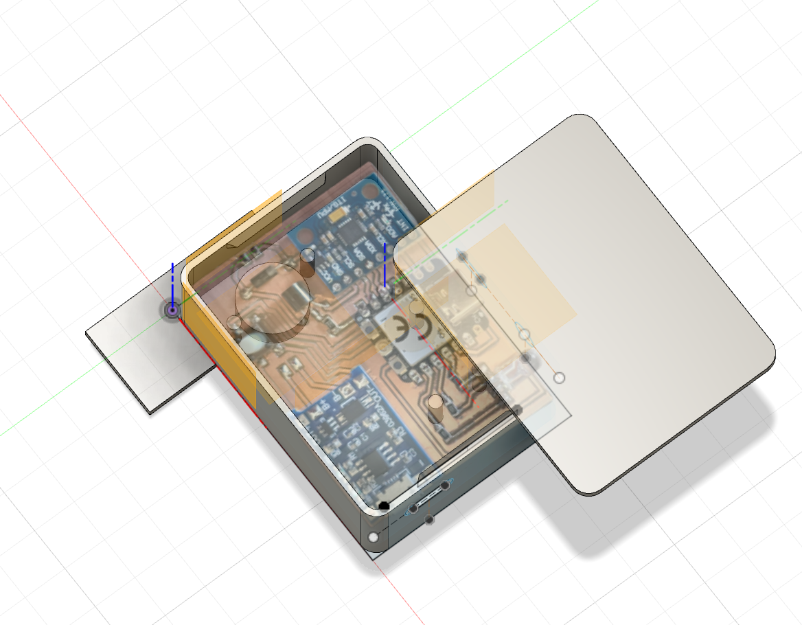
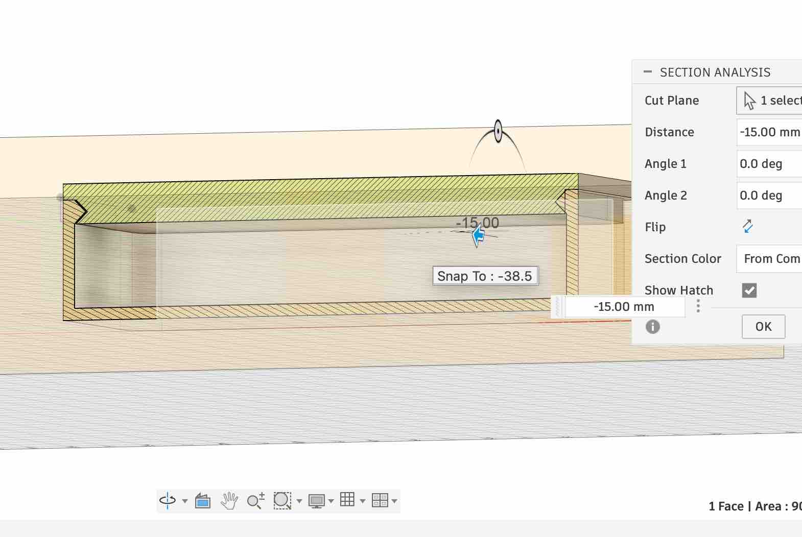
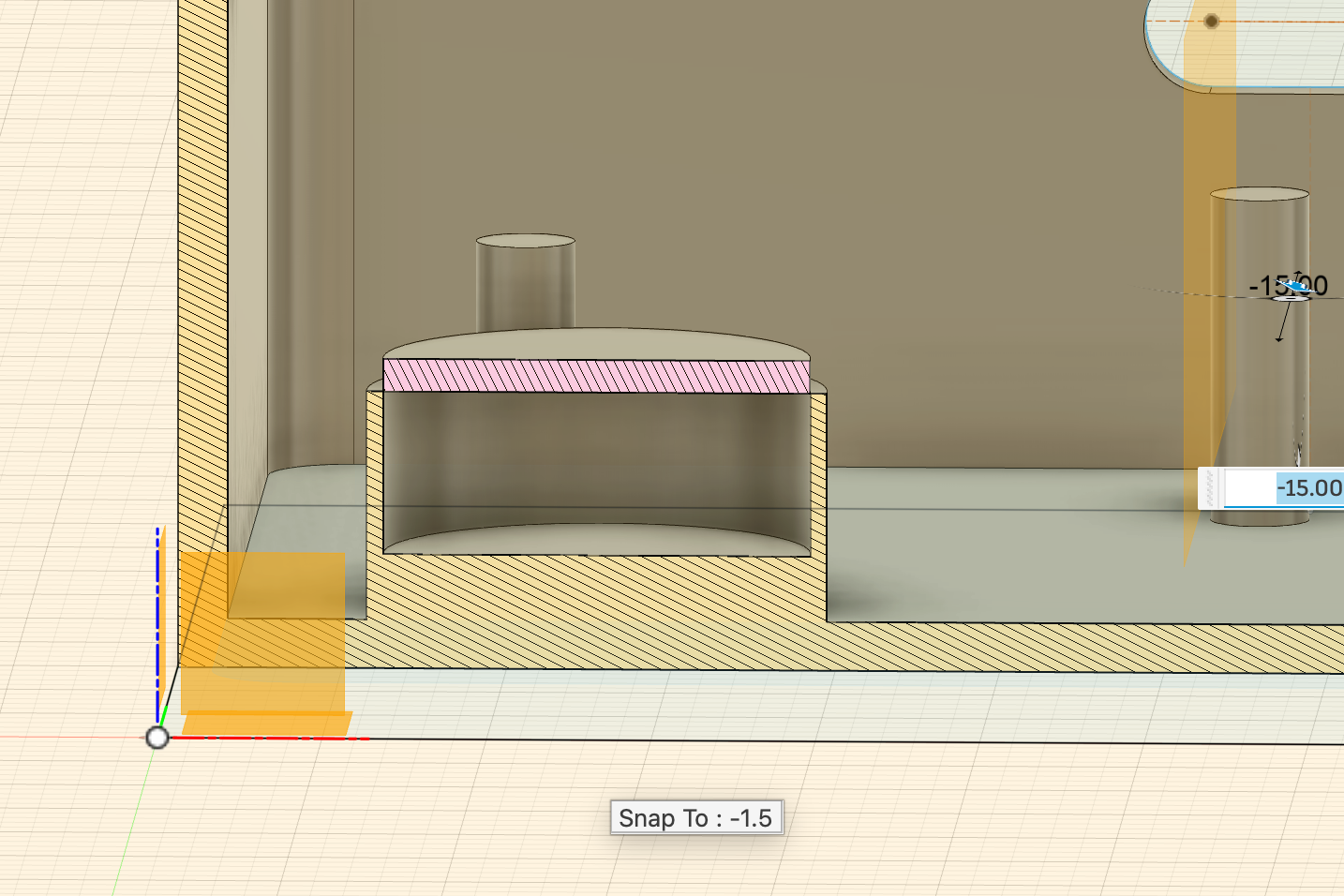
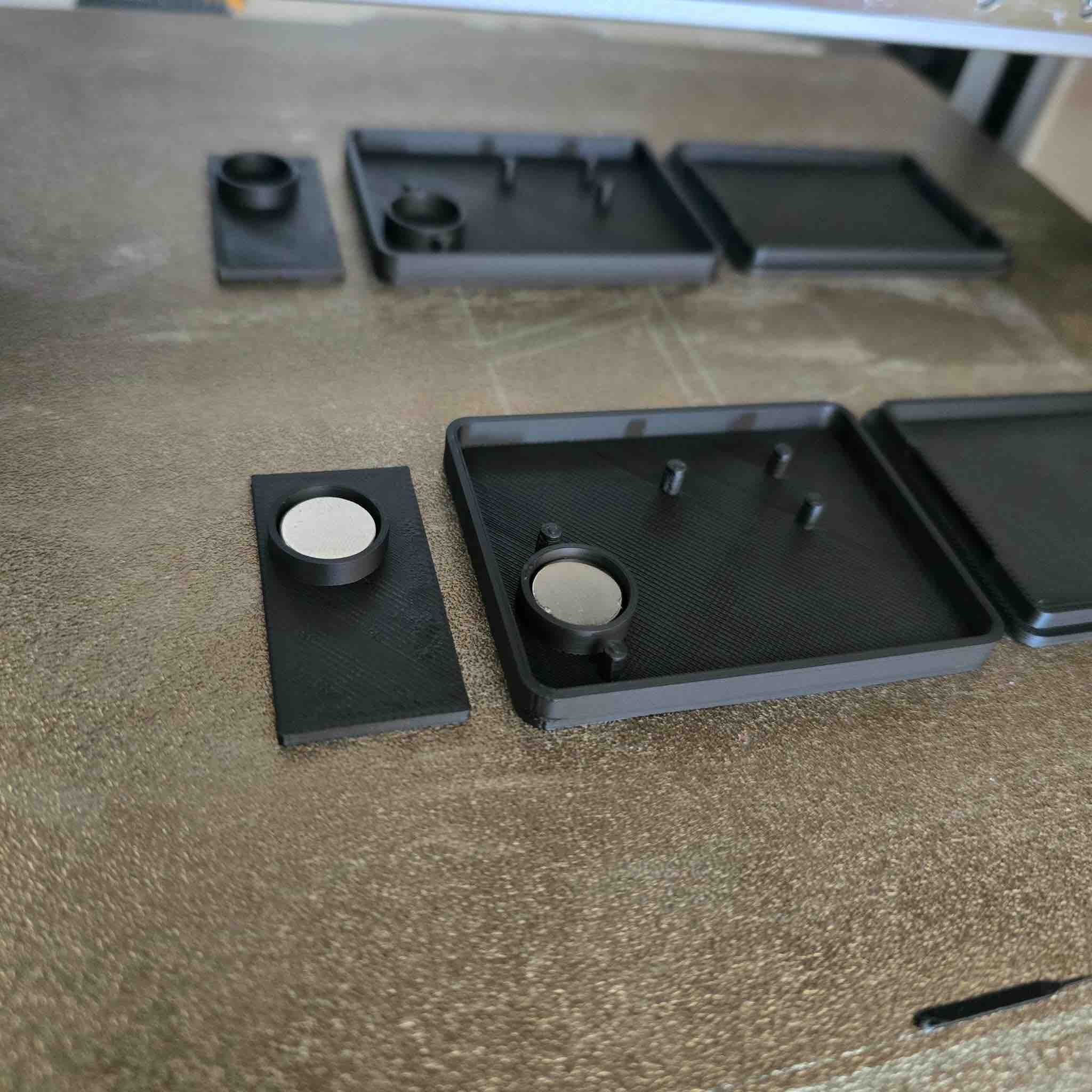
To make sure I'd be able to apply changes to the clip-case size later, I built a parametric design driven by constraints. Full details in Week 15 — System Integration. This is the workflow I followed: first take the measurements of the PCB and of every component I need access to → define the parametric sizes for the case (width, length, height, wall thickness) → start with the main case body → use offset construction planes to work on the LED top piece → create lips identical in size and position, opposing the ones on the case body, so the lid clicks shut → use the mirror feature in Fusion so all features are linked — any change applies to both halves → add internal pillars to hold the battery and route the wiring inside the case → add an empty chamber to hold the magnet → add a hole for the USB-C charging port and the charging module → add a window for the RGB LED so the indicator is clearly visible → use the inspection / analysis view to see the layer cuts and how the different bodies interact with each other → keep some intentional empty space so the printed body and lid actually click together with a slight friction fit.
04|01|02| 3D printing
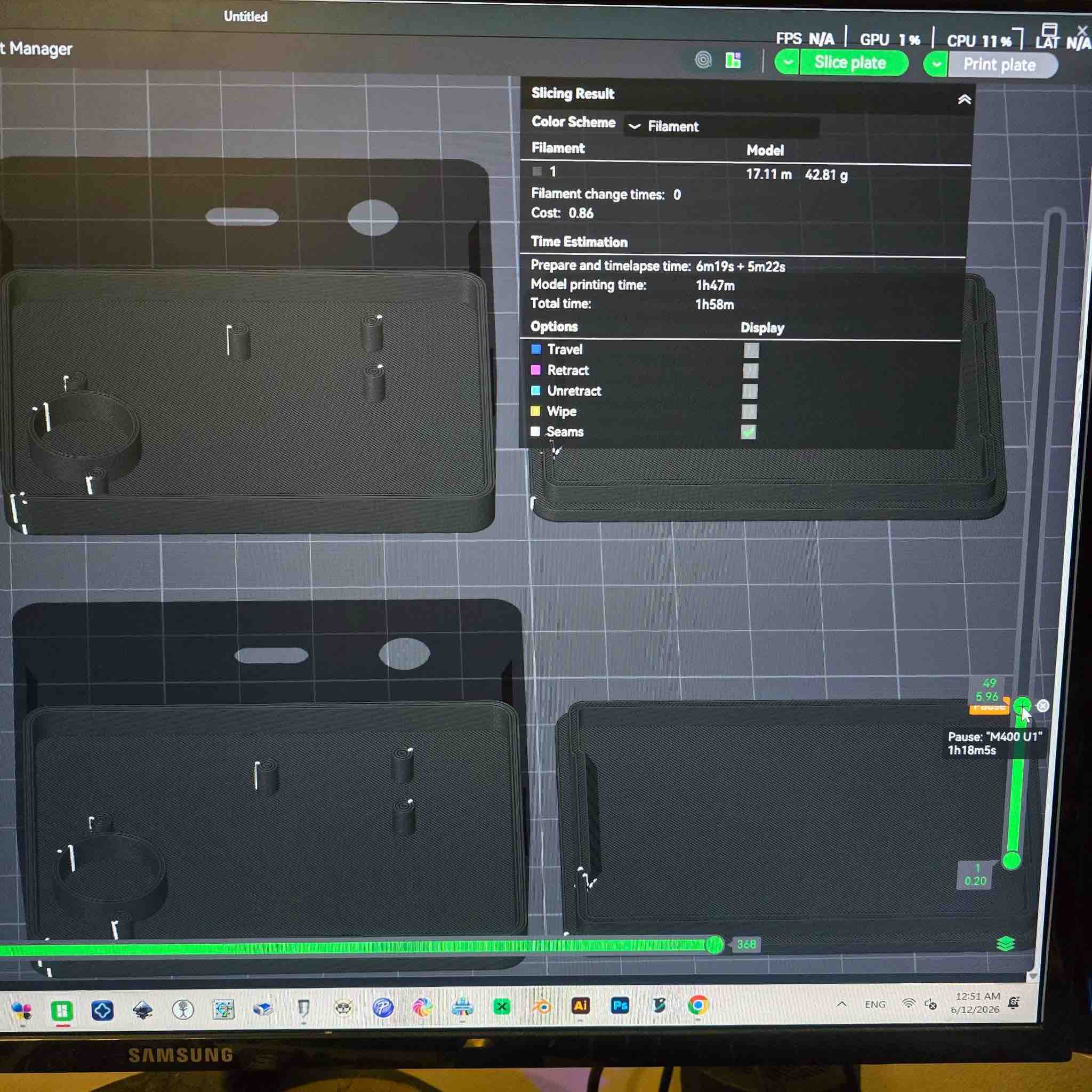
I printed the case on a Bambu Lab A1 with a 0.4 mm nozzle and black PLA filament. Workflow: export a STEP file from Fusion → import the file into Bambu Studio → realign the different bodies on the print bed → rotate both the clip body and the LED lid so they print with minimal support — reduces waste and improves the surface finish → as I needed two clips, I duplicated the shapes on the same bed → slice the design and select a pause layer just before the magnet chambers close over the top → review layer count and print time → start the print → when it reaches the pause layer → drop the magnets into the chambers, making sure they're placed with the right polarity so the attractive face matches the carry case (and they don't repel) → restart the print → once complete, remove all the parts from the bed.
04|01|03| Assembly
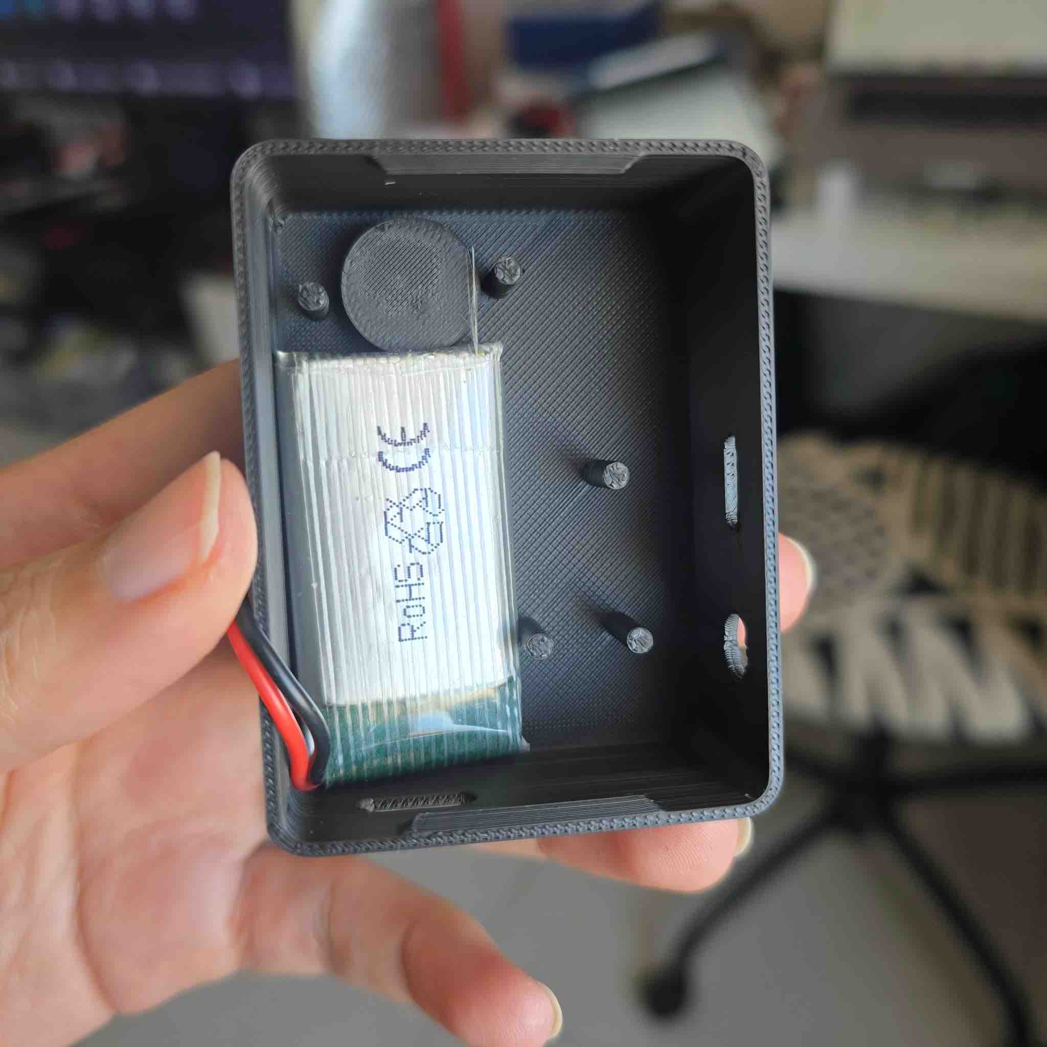
Documented in detail in Week 15 — System Integration. This is the workflow: first place the battery into the case and check the fit → then place the PCB into the case to check the size and flag any clearance issues → I found the case was the right size overall, but the case corners were rounded while the PCB corners were sharp → I changed the corresponding size values in the parametric model → I also added clearance for the battery wires to run up and connect to the PCB → reprint the case → re-assemble → this time it was a success — everything fit in place and the LED lid clicked closed.
04|01|04| Cover Moulding (Write-up to be added — silicone-mould cover process still pending.)
04|02| Wooden Case
04|02|01| CAD Design
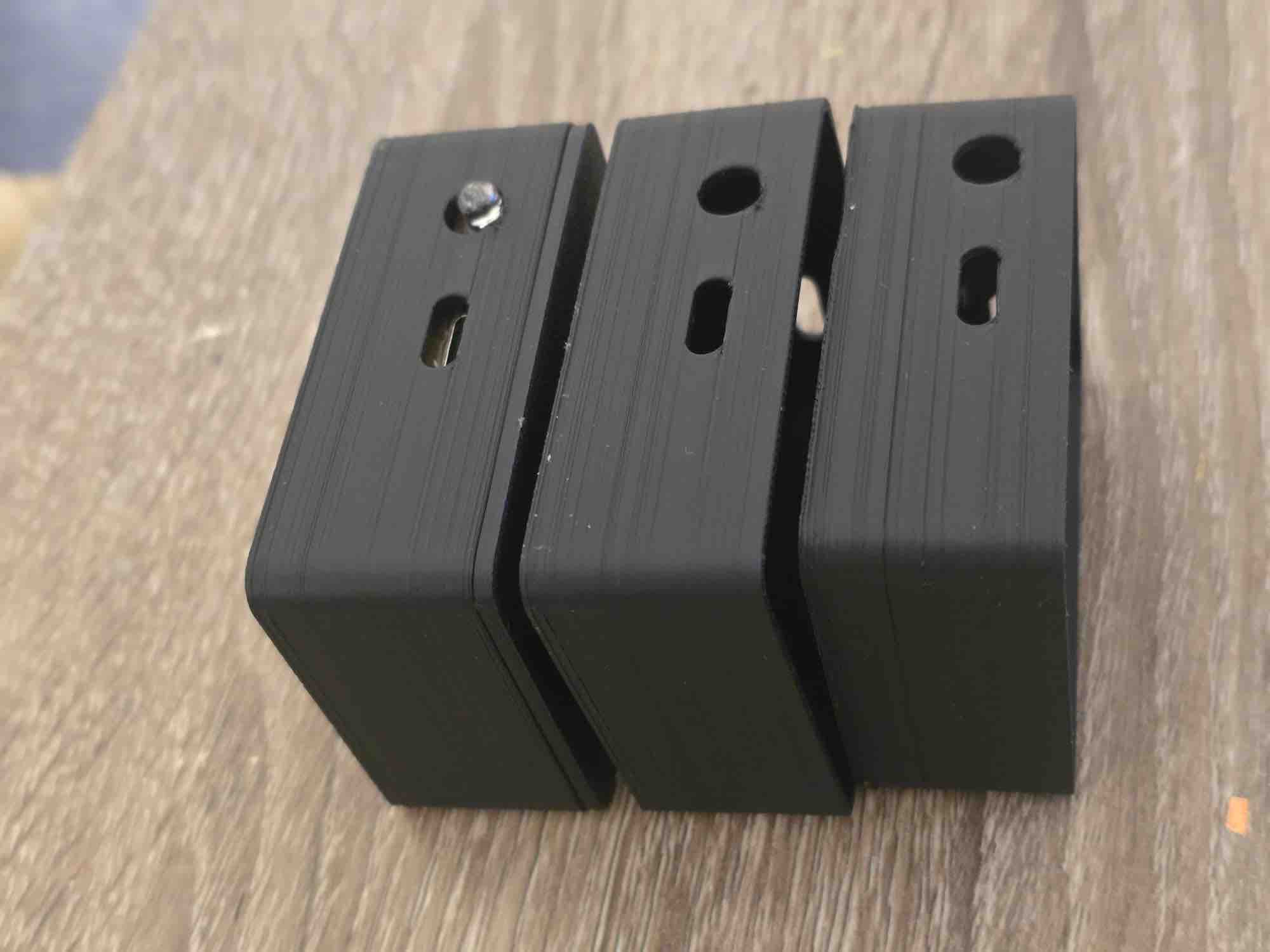
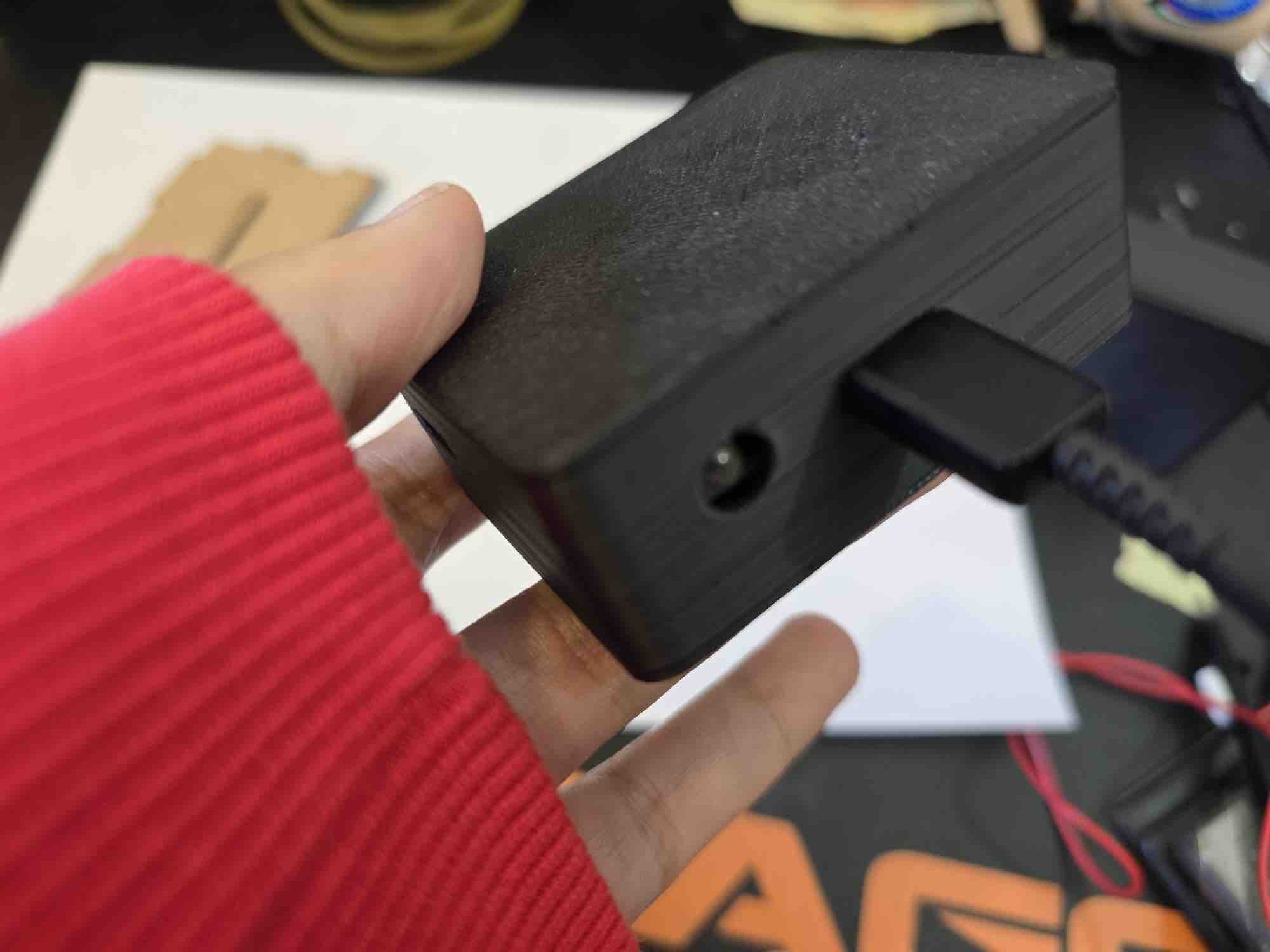
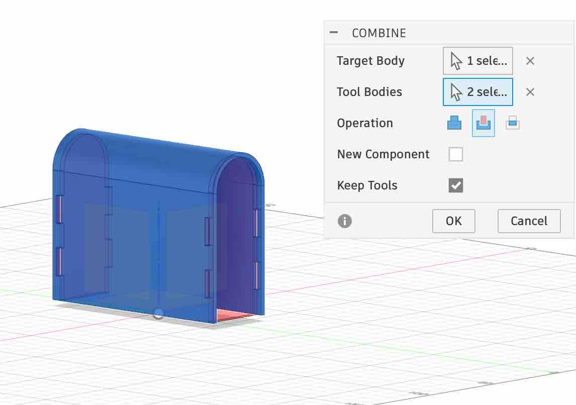
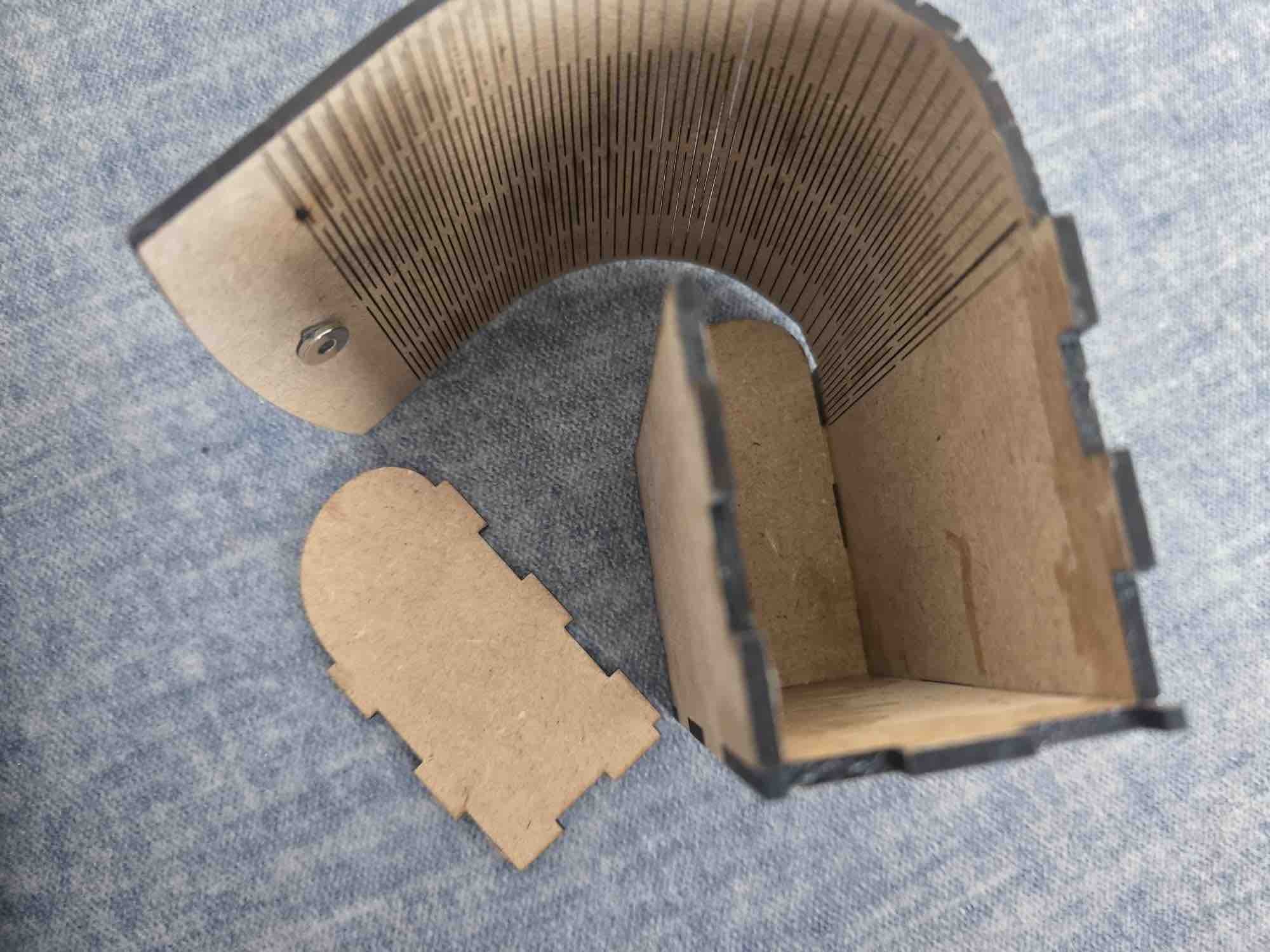
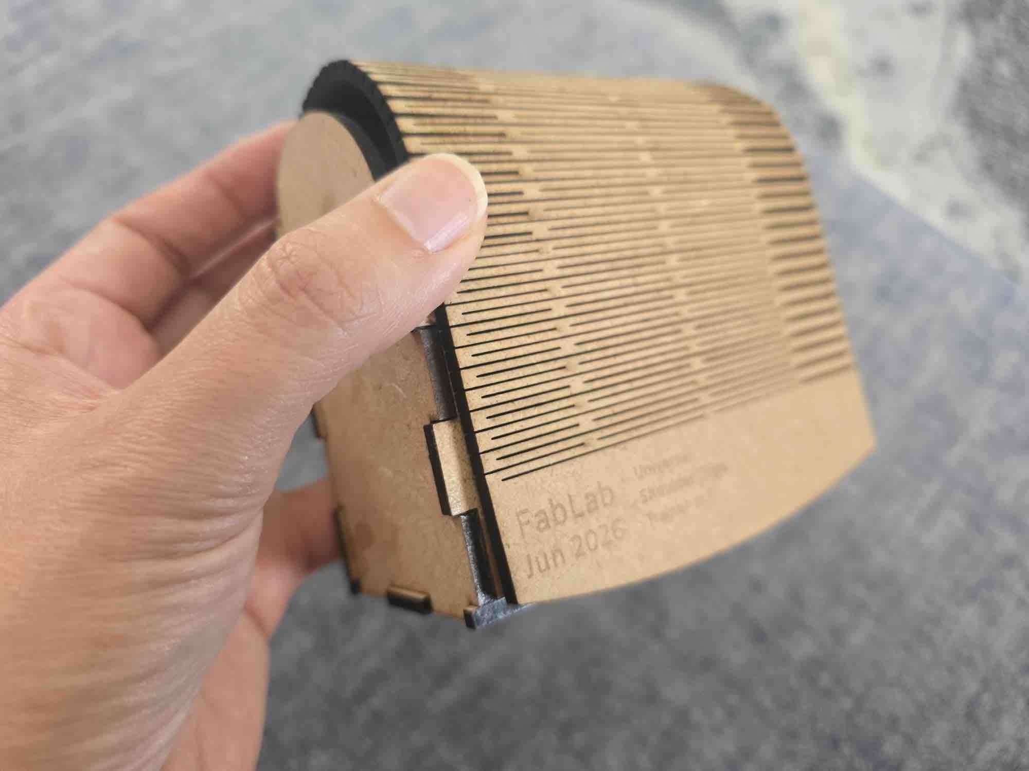
Based on the dimensions of the clips, I started designing the case with a living-hinge cover → I followed parametric-design rules so the case could absorb later changes — this case was originally designed back in Week 03 — Computer-Controlled Cutting → add the text I want to engrave on the case → reposition the parts to best utilise the sheet of wood and reduce burn risk along nested edges.
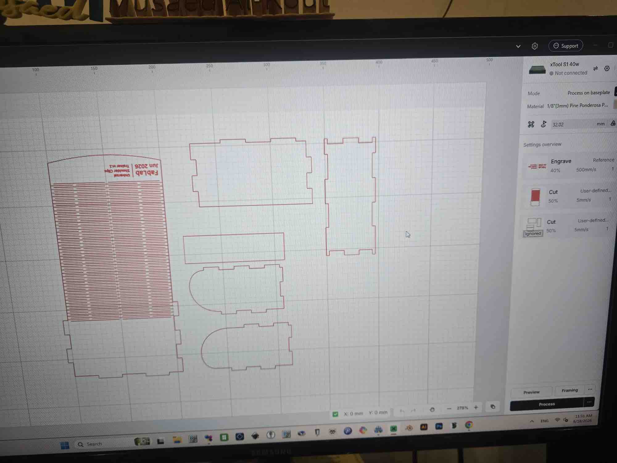
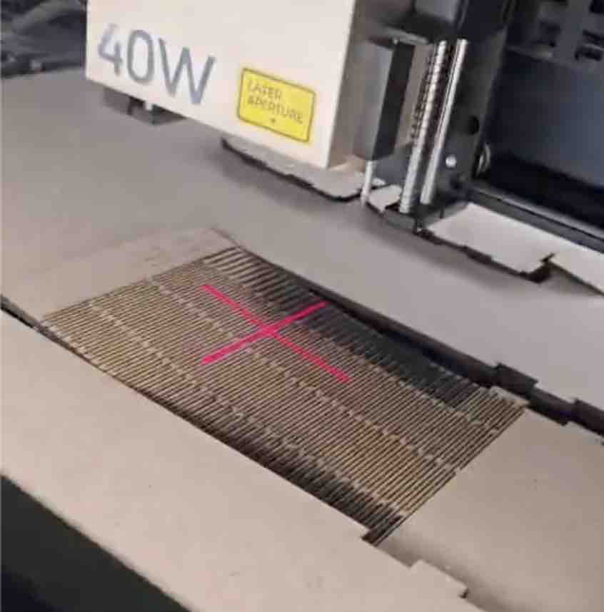
04|02|02| Laser Cut
After taking all the safety measures for operating the xTool S1 — documented in Week 03 → I loaded the 3 mm MDF sheet onto the bed → defined the origin / starting area → followed the cut rules I'd characterised earlier → assigned the engrave job to the text strokes at 40 % power, 500 mm/s → assigned the cut job to the outline shapes at 50 % power, 5 mm/s — the slow cut speed avoids burning the MDF → stood by the xTool while it ran (safety — never leave a running laser unattended) → removed the pieces → cleaned them of burn residue.
04|02|03| Assembly evaluation
I started by checking the living hinge bent to the exact angle needed → dry-fitted the cut pieces to confirm they slotted together → applied wood glue to the corner joints to bond them → placed small magnets with double-sided tape inside the case body and inside the lid (so the lid stays shut and the clips snap into place) → finally seated both clip cases inside the wooden carry case — fit confirmed.
05| Spiral Development
To continue working on this project, I would like to turn the wooden case into a wireless charging case for both clips and to have it indicate when a clip is missing.
On the coding side, I would program the microcontrollers to go into sleep mode once they are disconnected, and to wake up again when the app connects to them.
Also, if the user wishes to keep the last calibration and keep using the clips without the app, a mechanism will be added for that as well.
Fabrication Plan
Component
Description
Fabrication Method
Material
Fab Academy Skill Demonstrated
Wearable Posture Clip (×2)
Body-mounted clip housing the ESP32-C3 PCB, MPU6050, RGB LED, vibration motor, and battery — clips onto clothing or sits directly on the shoulder
FDM 3D printing (Bambu Lab A1), pause-and-place magnets
Custom PCB carrying the ESP32-C3, MPU6050 footprint, RGB LED, transistor + diode driver for the vibration motor, and the TP4056 charging-module footprint
Milled FR1 (CNC) + vinyl-cut copper tape for the second clip
Sized for the full build: 2 shoulder clips (left + right) and 1 laser-cut 2.8 mm MDF carry case. Prices are approximate USD on Amazon at time of writing and are best-checked against the linked search before ordering; many small parts (resistors, diodes, transistors, push buttons) are cheapest as multi-packs that cover the full build with parts left over for prototyping.
Item
Used in
Qty per clip
Qty for build (2clips + case)
Unit price (approx)
Subtotal (approx)
Where to buy
ESP32-C3 SuperMini (or XIAO ESP32-C3)
Main MCU — sensor read, RGB / vibration control, BLE
Notes on the BOM: (1) Small SMD-equivalent parts (resistors, diodes, transistors, buttons) are almost always cheaper as multi-packs than singles, so the "Subtotal" reflects the pack price even when only 2–6 are needed for the build. (2) The 1 KΩ and 10 KΩ resistors are bundled under one assortment kit because buying a kit is cheaper than two single-value reels. (3) Shipping to Kuwait via amazon.com or amazon.ae will add cost — checking amazon.ae for the same SKUs sometimes lands closer/faster. (4) Quantities for items milled or cut at the lab (FR1 blanks, MDF sheet) include one spare for re-runs.
Main Questions
Question
Answer
What does it do?
It's a smart wearable system that corrects posture in real time. Two clips — one on each shoulder — use MPU6050 IMU sensors to track body alignment. If the user slouches past a configurable angle threshold for longer than a configurable delay, the clips vibrate as a tactile reminder and the RGB LED switches from steady green to flashing. The clips talk to a mobile app I built in MIT App Inventor that handles calibration, vibration strength, delay, and angle-threshold settings — and the two clips talk to each other over ESP-NOW so the app only needs one BLE connection.
Who's done what beforehand?
The concept of posture biofeedback is well established in both commercial and maker communities. I personally used the Upright device during my horse-riding classes, which gave me first-hand experience of how effective real-time vibration alerts can be for maintaining spinal alignment during active movement. In the Fab Academy community I've seen students explore similar themes but with different architectures: Nadine Uwineza used flex sensors for spinal tracking, and Praveen Kumar focused on ESP32 + MPU6050 integration. My project specifically targets shoulder symmetry, inspired by my yoga-teaching experience.
What sources did you use?
This project was an exercise in spiral development — I constantly simplified the design to reach a functional, reliable Minimum Viable Product (MVP).
The Fab Academy community: the global archive of previous projects was my main source for cross-referencing approaches.
VujaDé team and instructors: my local team and instructors at the VujaDé Innovations Lab were essential — particularly for the electronics-design and PCB-milling phases.
AI tools: I integrated AI into my workflow for both coding and documentation. While I experimented with ChatGPT, my two preferred tools were Gemini (paired-programming for MicroPython + App Inventor blocks) and Claude Desktop (documentation review and audit). See the audit report.
Personal experience: my Upright posture device (used during horse-riding classes) and my 200-hour yoga teaching practice shaped the dual-shoulder symmetry framing that makes this project different from the spine-sensor designs already in the FA archive.
What did you design?
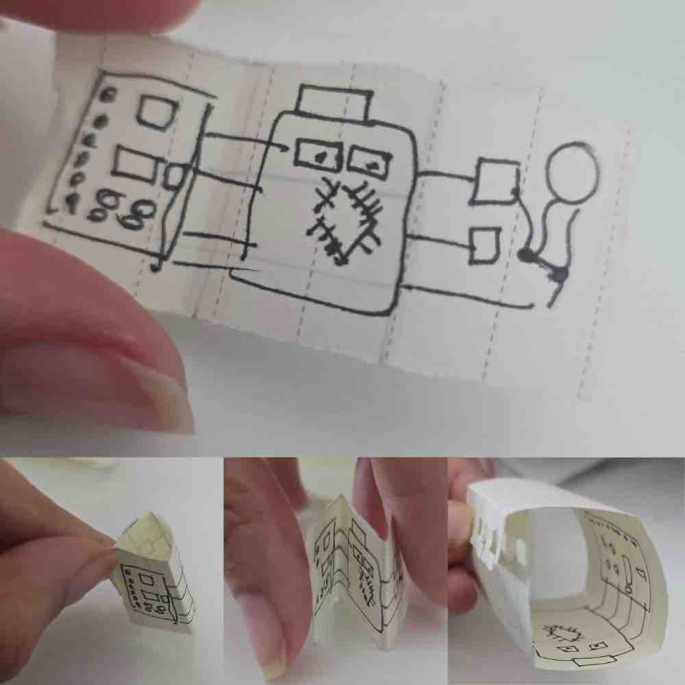
I designed quite a lot. I created the custom PCB for the shoulder clips in KiCad (see Week 06 + Week 08), the 3D-printed parametric clip housings with magnet chambers and pause-and-place magnets (see Week 05 + Week 15), the laser-cut MDF carry case with a living hinge (see Week 03), and the entire mobile app interface in MIT App Inventor (see Week 14 + Week 15). I started with a complex shoulder-pad vest idea (cardboard prototype in Week 03) but simplified it into these modular clips.
What materials and components were used?
The main parts are 2× ESP32-C3 SuperMini / XIAO controllers, 2× MPU6050 (GY-521) IMUs, 2× disc vibration motors, 2× RGB LEDs (common anode), 2× 2N2222A driver transistors + 1N4001 flyback diodes, 2× TP4056 charging modules, 2× LiPo batteries (different sizes — sourcing constraint), plus button switches, magnets, hookup wire, and lead-free solder. For the clip housings I used black PLA filament; for the carry case I used 2.8 mm MDF, inspired by my DJI Mic case. Full part list in the BOM above.
Where did they come from?
Some from the local Kuwait market, some ordered online (Amazon — see the BOM for the exact search links), and some from the VujaDé Innovations Lab in Saudi Arabia. The regional supply situation in 2026 meant lead times were unpredictable, which is why a few of the parts (notably the two LiPo batteries) ended up in different sizes — I had to use whatever was available when the deadline approached.
How much did they cost?
≈ $160 USD for the full build (2 clips + 1 MDF carry case), excluding shipping and tax. Full breakdown with per-line subtotals in the BOM.
What parts and systems were made?
Three main systems plus a carry case: (1) the hardware clips — custom milled FR1 PCB / vinyl-cut copper-tape PCB, soldered components, 3D-printed parametric housing with pause-and-place magnets (see W08, W09, W10, W15); (2) the communication layer — BLE between left clip and phone, ESP-NOW between clips (see W16); (3) the mobile app — App Inventor UI for calibration, threshold sliders, and live status (see W14 + W15); plus (4) the laser-cut MDF carry case with a living hinge for storing and transporting both clips (see W03).
What tools and processes were used?
KiCad for PCB design (+ FlatCAM for the G-code), an Easel-driven CNC mill for the FR1 boards (with vinyl-cut copper tape as the fallback when FR1 stock ran out — see W08 + W10), FDM 3D printing on the Bambu Lab A1 for the clip housings (with a pause-and-place layer for the magnets), and laser cutting on the xTool S1 for the MDF carry case (with living hinges from W03). For code I used MicroPython on Thonny for the clip firmware (see W04) and MIT App Inventor for the phone app. Spiral development methodology throughout — each week added one usable layer.
What questions were answered?
Can two separate sensors communicate reliably with one app? Yes — but not the way I originally planned. After trying to give each clip its own BLE link to the app and watching the App Inventor block logic balloon, I pivoted: the left clip is the gateway, with BLE to the phone and ESP-NOW to the right clip. The phone only ever maintains one BLE session — see §03|03 above and the full write-up in Week 16. Can we filter out false-positive slouching? Yes — a user-configurable delay in the firmware ignores brief deviations. Is a dual-shoulder setup better than a single spine sensor? For me, it gives much better feedback on shoulder rounding — symmetry isn't visible from one sensor. Can the case charge the clips wirelessly? Not yet — scoped in §05 Spiral Development for the next revision.
What worked? What didn't?
Worked
BLE connection between the two microcontrollers and the app (via the left clip as gateway).
Calibration and real-time angle tracking are smooth and responsive.
Status / feedback messages flow cleanly between the app and the clips.
The vibration motor triggers when the shoulder angle deviates past the threshold defined during calibration.
The RGB LED gives a clear visual state (pairing, calibrating, alert) without needing the phone in hand.
Didn't work / had to pivot or drop
My first concept — a wearable vest with hidden wiring — was too complicated. I pivoted to the wireless clip design, which is much more practical.
The on/off button on the clips: I had to control the power flow in software and start the vibration motor at 0% until the user presses calibration.
Architectural pivot: I originally wanted both clips paired to the app directly over BLE. The App Inventor blocks ballooned (everything had to be duplicated L/R and demultiplexed), so I made the left clip the gateway — BLE to the phone, ESP-NOW to the right clip. Full pivot rationale in §03|03 above and Week 16.
The gateway pivot meant dropping persistent calibration (clips remembering the last baseline so the user doesn't reconnect and recalibrate every time) — adding persistent state on top of the gateway pattern needed another layer of synchronisation I couldn't fit before the deadline. Moved to the next spiral.
The wireless-charging case is still aspirational — scoped in §05 but not delivered for this presentation.
How was it evaluated?
Evaluation criteria: (1) Functional — calibration captures a baseline and the threshold triggers vibration within ≈ 1 s; (2) Wearable — fits a real shoulder and the clip mounts without distorting clothing; (3) Usable — a first-time user can pair, calibrate, and set thresholds from the app in < 2 minutes; (4) Reliable — BLE + ESP-NOW link survives a 30-minute wear session without dropouts. Still being measured against criteria 3 and 4 in the final week.
What are the implications?
This project shows that personalised health tech doesn't have to be a generic "one size fits all" product. My background in yoga and body-mechanics anatomy shaped the dual-shoulder symmetry framing — which differentiates it from the spine-sensor and full-back wearables already in the FA archive and on the market. The same architecture (BLE clip-to-phone + ESP-NOW clip-to-clip + parametric 3D-printed housing + laser-cut carry case) is directly adaptable to other domains where symmetric body cues matter — physiotherapy rehab, post-injury gait re-training, dance and movement coaching, or even sports-form feedback. Open-hardware dissemination (W18) means the next FabLab cohort can pick this up, fork it, and adapt it for their own users.
Reflection
What worked
Letting the design get simpler over time — moving from a full sensor vest, to a hanger, to a shoulder strap, and finally to two small clips — made the project achievable inside the academy timeline.
The gateway architecture pivot — left clip = BLE-to-app gateway + ESP-NOW-to-right-clip relay (see §03|03 and W16) — is the single design decision that made the system actually shippable. One BLE session in the app, one source of truth, and ESP-NOW is purpose-built for the millisecond-latency device-to-device chatter we need.
My yoga, body-mechanics, and horse-riding (Upright device) background gave the project a clear, grounded purpose — the dual-shoulder symmetry framing is what makes it different from the spine-sensor designs in the FA archive.
Treating the final project as a spiral from day one — every week added one usable layer (idea → 2D/3D form → microcontroller → input → output → integration → packaging), so by W17 the build was already in hand, not still in pieces.
Splitting AI tools by task — Claude Desktop for documentation review, Gemini for paired-programming — avoided cross-task hallucinations and gave each tool a narrow, clear job.
Costing the build properly (the BOM came to ≈ $160 USD for 2 clips + 1 MDF case) made the Applications and Implications questions concrete, not hand-waved.
The packaging chain is now end-to-end: FreeCAD parametric model → Bambu Lab A1 print with pause-and-place magnets → PCB / battery fit-test → reprint with widened tolerances → laser-cut MDF carry case with living hinges. Every step of section 04 is a real, documented workflow.
The full firmware (BLE registration, calibration interrupt, slump-detection main loop, fail-safe IRQ handler) ships on this page as the actual code I flashed onto both clips — not pseudo-code, not a sketch. The CLIP_SIDE = "FBL_L" / "FBL_R" single-line toggle is the only thing that differs between the two boards.
The Gantt-style schedule, the Fabrication Plan table, the BOM, the Original Files table, and the Main Questions all live on one page now — the project tells its own story to an evaluator without having to chase ten separate weeks.
What didn't
The early wearable-vest concept was too complex — hidden wiring was never going to work inside the academy timeline.
The flexible copper-tape PCB kept failing at the soldering stage; ran out of FR1 stock and had to use the vinyl-cut copper-tape route for the second clip.
The wireless-charging case is still the hardest unsolved piece — scoped in section 05 (Spiral Development) but moved to the next revision.
The regional escalation forced a three-week WRO Kuwait detour, compressing the final-build window to a few weeks.
Parts lead times slipped — I had to reuse components from previous devices, end up with two different LiPo battery sizes (one per clip), and rework the parametric model around what I could actually source.
The MPU6050 soldering on the through-hole-to-SMD conversion is mechanically weak — the drop test in W15 separated the IMU from the PCB. Logged for the next revision (use an SMD-package MPU).
The "How was it evaluated?" answer is still partial — criteria 3 (first-time user under 2 minutes) and 4 (30-minute reliability) aren't yet fully measured.
The Cover Moulding sub-section (04|01|04) is still a placeholder — the silicone-mould lid workflow needs to be written up before presentation.
The video and summary slide for the W18 presentation aren't filmed yet.
What I'd do differently
Prototype the simplest viable form first, then add complexity — instead of designing the most ambitious version up front.
Freeze the core design decisions earlier so the electronics and case could develop in parallel.
Order PCB stock, milling bits, and matched LiPo batteries well ahead — supply chain has a longer lead time than any week's assignment.
Lock the BOM and start the part orders in Week 01, not when the integration week arrives.
Specify SMD packages from the start (LEDs, MPU) — every through-hole-to-SMD conversion in this project became a mechanical weak point at integration.
Write the evaluation criteria before the build, not after — that way each week's spiral feeds a clear yes / no check.
Reserve an explicit buffer week for the "stretch" features (wireless charging, persistent calibration) so they have somewhere to land if the core build slips.
Record short video clips of each subsystem as it's built — by W18 the presentation video is then just edit-and-cut, not a fresh shoot under deadline pressure.
Key learnings
Spiral development works: build a rough version, learn from it, refine — repeat. By the time integration arrives, the system is just the spirals stacked.
A wearable is a system, not a board — clips, case, app, and carry case all have to be designed together, and the radio split (BLE phone↔clip, ESP-NOW clip↔clip) matters as much as the firmware. See §03|03 for the before/after diagram of why the gateway pattern beats two parallel BLE sessions for this kind of dual-sensor wearable.
Domain knowledge (here, posture and anatomy from yoga + horse-riding) is what makes the engineering decisions meaningful — the dual-shoulder symmetry framing came from that, not from the tech.
A minimum-viable product framing is not a compromise — it's the discipline that lets a real wearable get built under regional, supply-chain, and time pressure. Every dropped feature (vest → clip, two BLE sessions → BLE+ESP-NOW, persistent calibration → manual recalibration) made the system more likely to actually work on demo day.
Packaging is layered: PCB → 3D-printed clip case → laser-cut MDF carry case. Each layer has its own joinery (solder / printed snap-lip flexure / living hinge), its own material, and its own surface finish — getting the boundary right between layers is the integration work.
QA prevents defects, QC detects them — the difference matters. Designing the pause-and-place magnet step (QA) prevents wrong-polarity assemblies that no amount of testing (QC) can recover from once the case has printed shut.
This page sits on top of W01 → W16 — every spiral, every reused skill, every cross-link — and lands the final project at ≈ $160 USD: two working clips with custom firmware, an MIT App Inventor app, and a laser-cut MDF carry case. The next spirals (wireless charging, persistent calibration, SMD MPU, cover moulding) are scoped on the same page so the project is also a clear roadmap, not just a milestone.
Original Files
All design files, source code, and references for the project. Replace each # link below with the real file URL (GitLab raw link, repo path, or local file) once uploaded.

 Long hours at a desk or lab can silently damage your posture. Poor alignment affects the spine and ribcage, causes certain muscles to become inactive while others are chronically overworked — leading to pain, discomfort, and long-term injury.
 A lightweight wearable device that corrects posture in real time by tracking two fixed points on the shoulders. By monitoring shoulder alignment, the device guides the neck, back, and core into a healthier position — making good posture feel natural and comfortable. Over time, it trains the body-mind connection so correct posture becomes automatic.


