Schedule
The ideal option was to finish each part of the integration as I went through the weeks of the FabLab programme. Unfortunately, in 2026 a war started in the region and it affected two critical factors. First, the availability and supply of the inventory needed to fulfil the assignments; this caused huge stress and an accumulation of work to be done in a very short window. Second, I hold a leadership position with WRO Kuwait, and since October 2025 I'd prepared and organised my work so it wouldn't affect my commitment to FabLab. Due to the war, my 8-month plan lost its value — I had to accept a financial loss and re-strategise, re-plan, and re-implement the full WRO project in 2 months, which affected my commitment to FabLab too. I decided to take 3 weeks off FabLab (W13, W14, W15) to finish my country-level responsibilities so I could commit fully to FabLab through June and complete every assignment for graduation in June.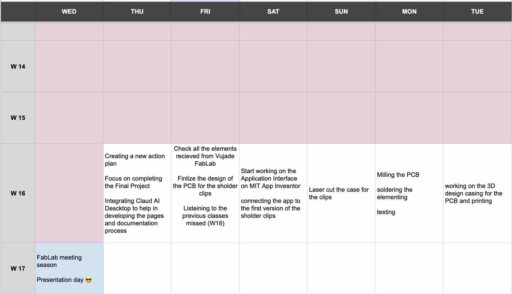
The process
Individual assignment:
00: Plan for system integration — three design phases
I treated the integration as three sequential design phases — the standard engineering breakdown that maps onto how each subsystem actually came together over the academy:
Conceptual design
"What is it, and why?" Started as a full sensor vest, evolved through a hanger and a shoulder strap, and converged on two wireless clips + an app + a charging case. Documented in Week 03, Week 05, and the final-project page.Detailed design
"How does it ship?" This week — PCB-to-case fit, battery sockets, USB / LED through-holes, magnet pockets, wire routing inside the clip, and the laser-cut MDF carry case. Resolution that turns a working breadboard into a wearable.Ideation Design — the Conceptual-design phase, in detail
This is the work behind the "Conceptual design" card at the top of the page — the form-factor and packaging concepts I sketched and prototyped before any of the integration here was possible. It splits naturally into two tracks: the wearable itself, and the case that holds and charges it.
Track 1 — Wearable form factor (vest → strap → clips)
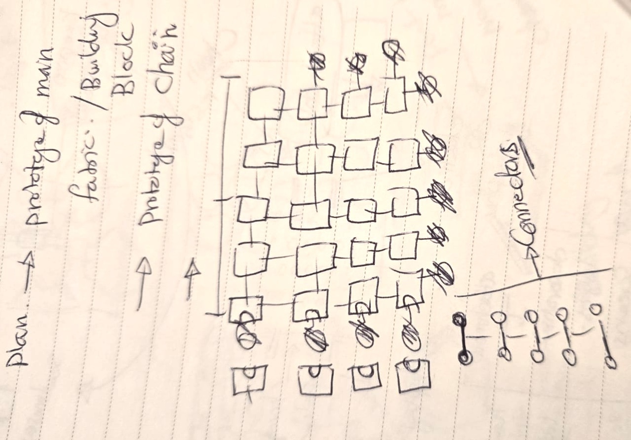
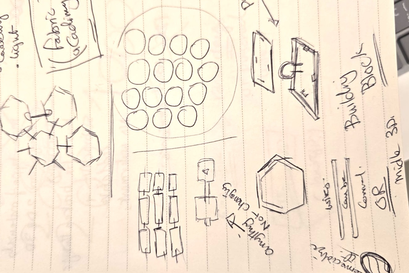
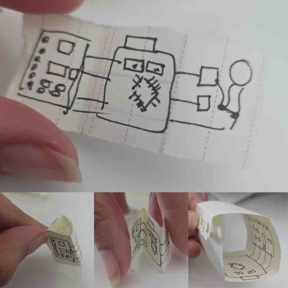
01 | First idea: building-block tiles that make up the main fabric of a sensor vest, with the wiring hidden inside the printed tiles.
02 | Defining where to place the gyro sensors — shoulders, neck, spine, chest, and core.
03 | A wireless charging station that the whole vest sits in.
04 | As I progressed through the weeks and saw my colleagues' projects, I tried to simplify. I created a version with a flexible strap, but the wiring was still an issue (see the cardboard prototype work in Week 03).
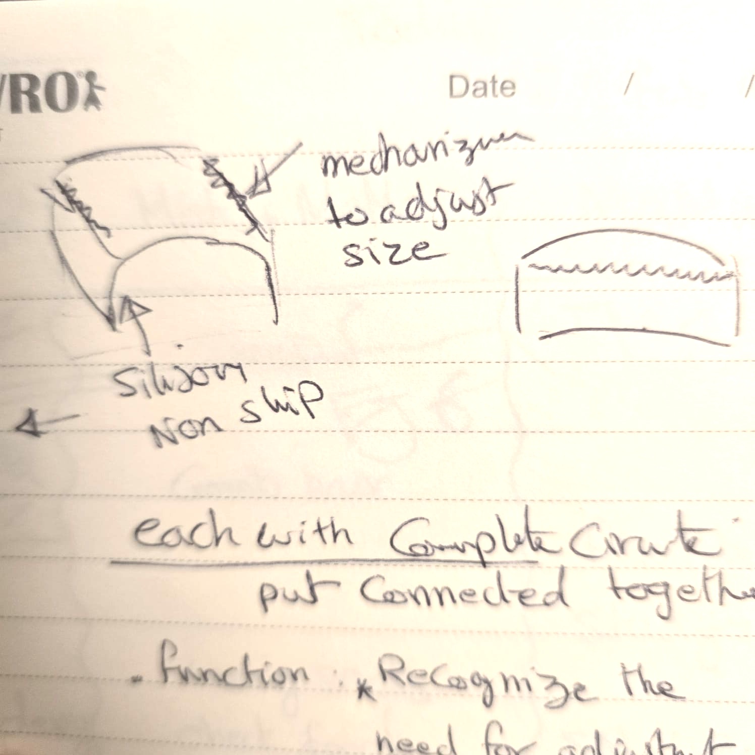
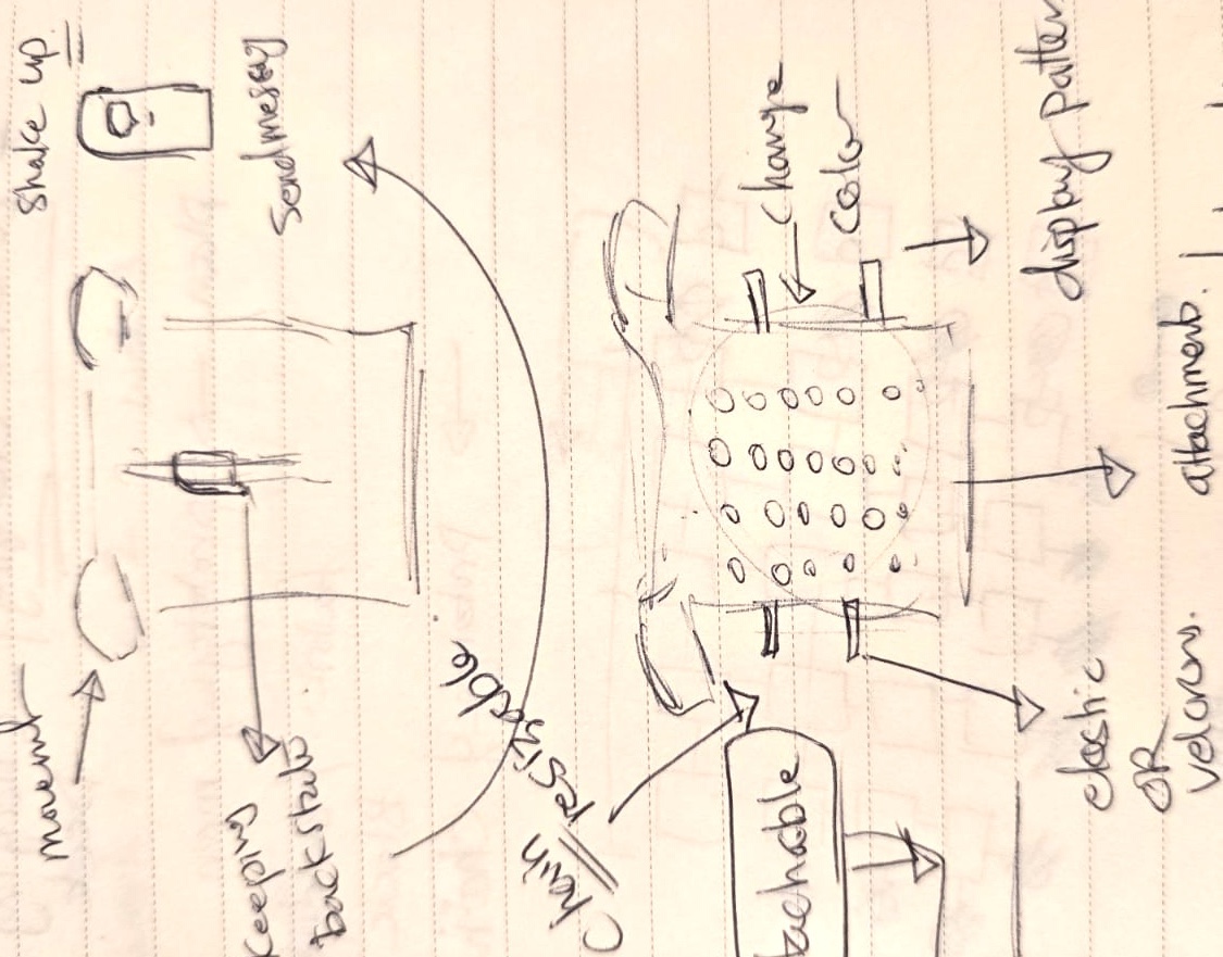
05 | Next iteration: wireless-connected shoulder pads that communicate with each other and stay stable on the shoulder — either directly on the skin or on top of clothing.
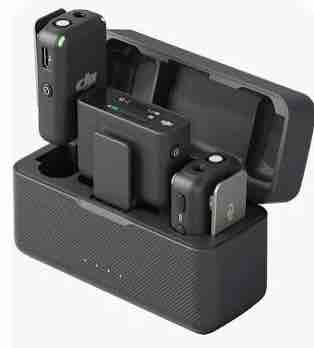
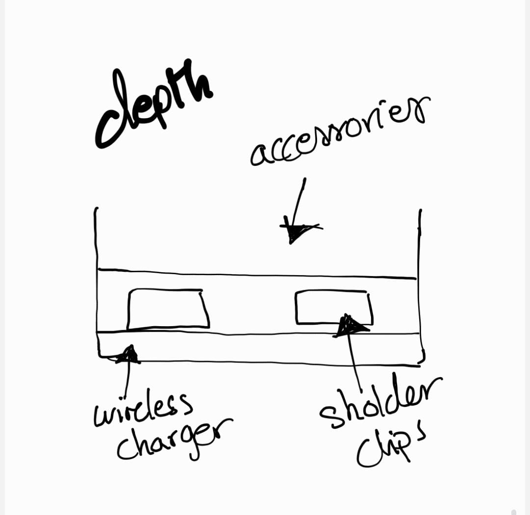
06 | A rechargeable station is necessary for this kind of project — looking at different ways to combine a case and a charger, inspired by my DJI Mic case.

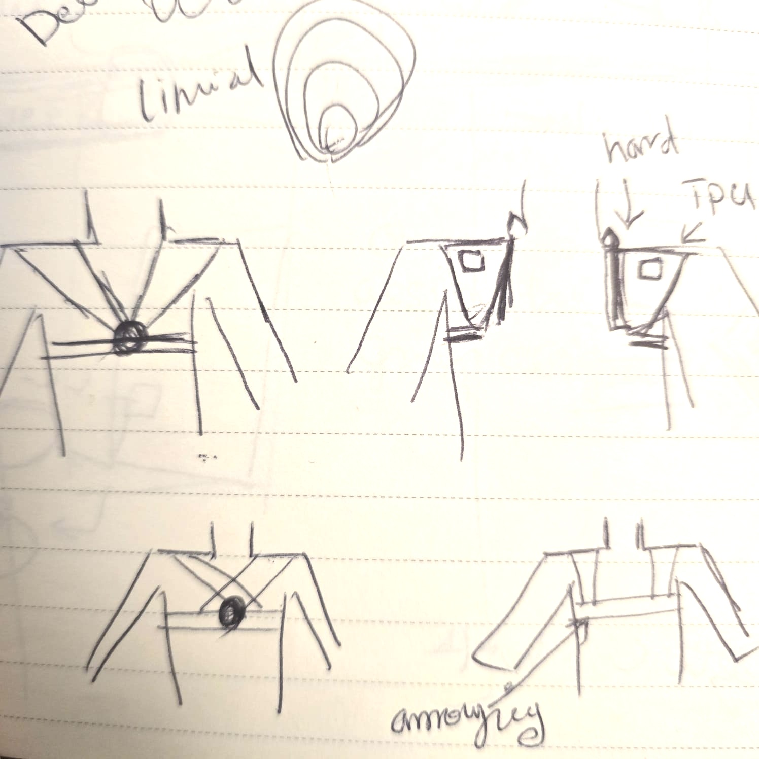
07 | Converged form: the main circuit lives in a small box that sits on the shoulder.
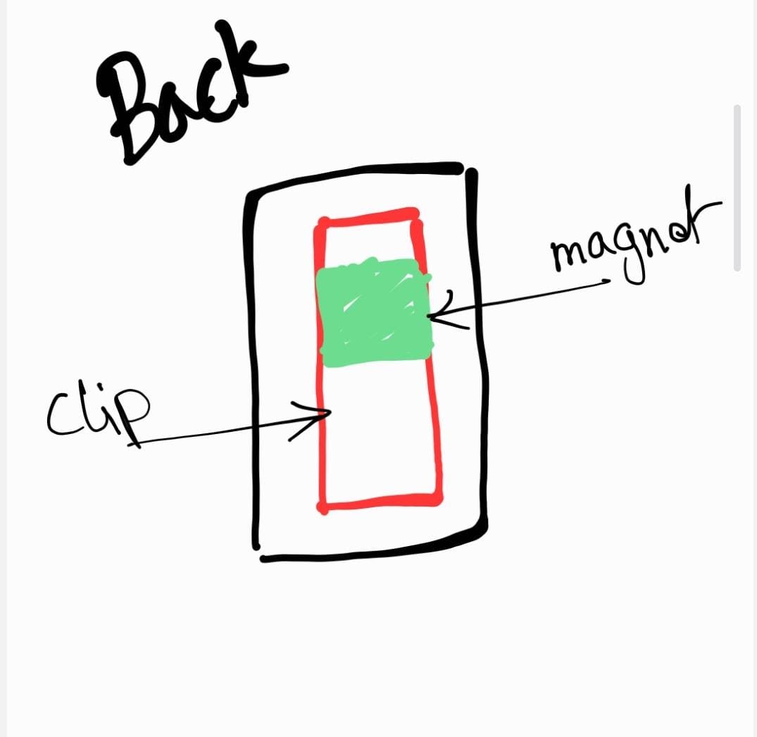
08 | Two attachment options: a fabric clip, or a magnet.
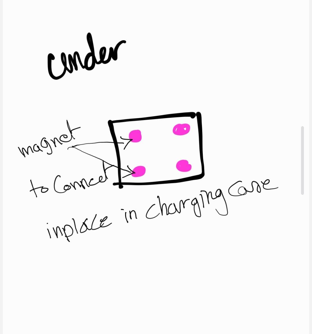
09 | Additional magnets in the underside of the case so the shoulder clips snap into place when seated in the carry case.
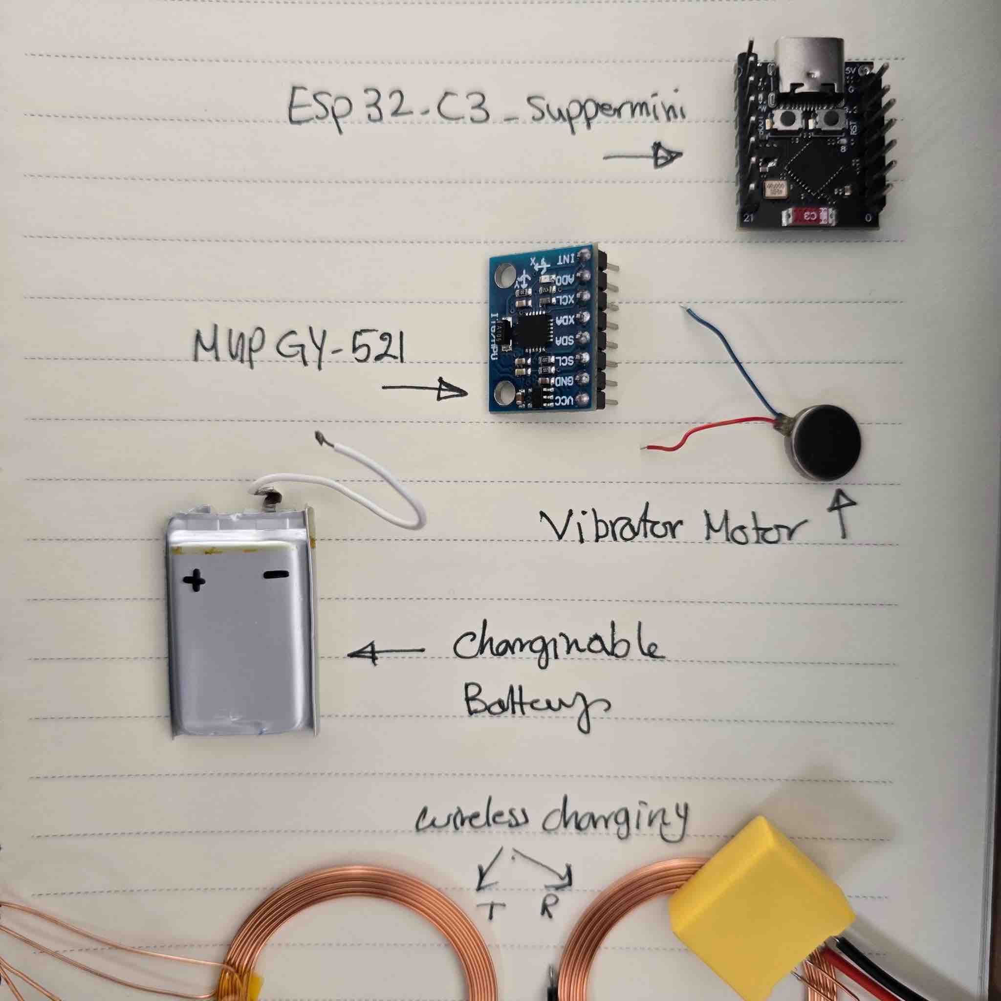
10 | Main parts per clip: ESP32-C3 SuperMini microcontroller (see W04) → MPU6050 (GY-521) IMU (see W09) → vibration motor + RGB LED (see W10), programmed in MicroPython on Thonny.
11 | The drawn PCB layout — could also be built as a flexible PCB with copper tape on a 3D-printed support (the vinyl-cut PCB approach I documented in W08 and W10).
12 | I also found a way to embed the routes and wires inside the 3D design itself, as demonstrated in this guide.
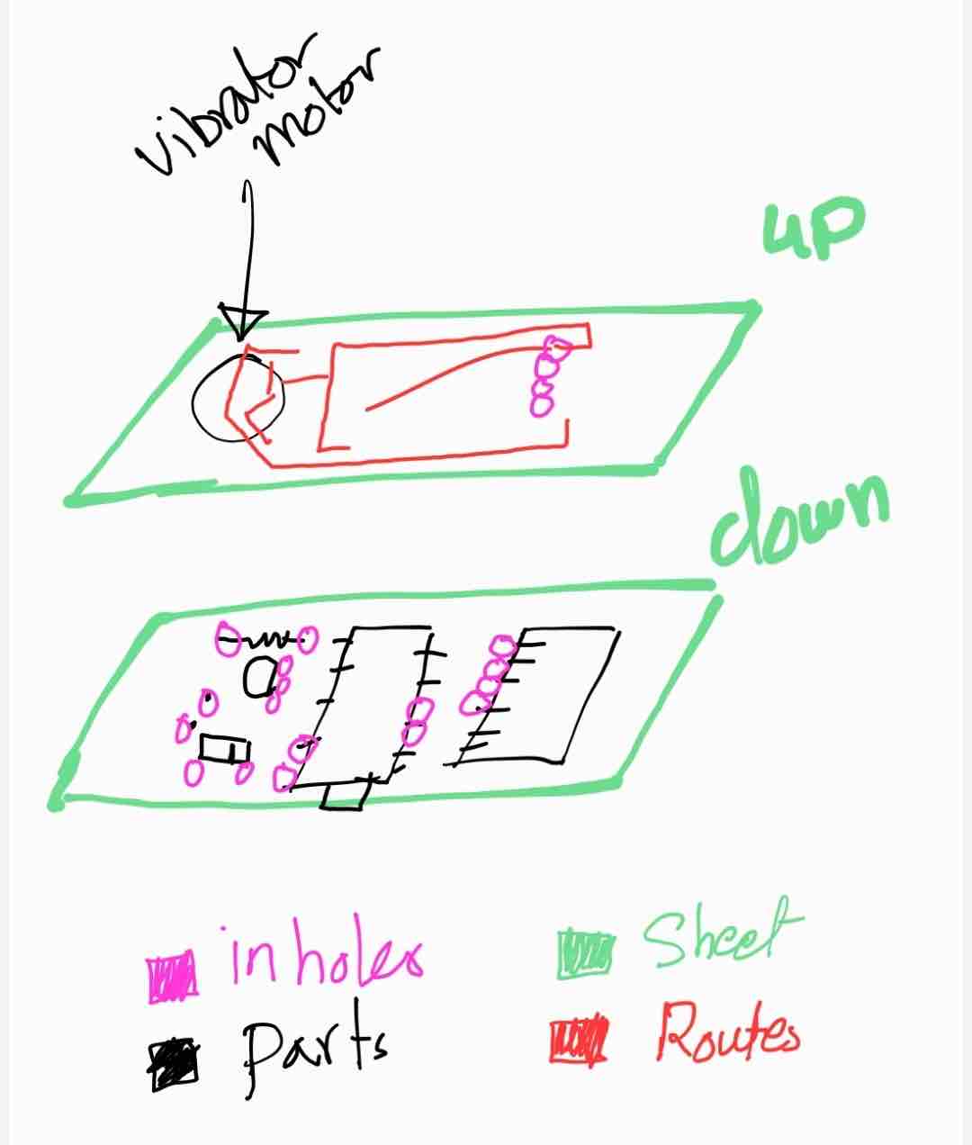
13 | Decision: start with a flat, rigid PCB, and spiral toward wireless charging and a flexible circuit in later revisions.
Track 2 — Charging case concept
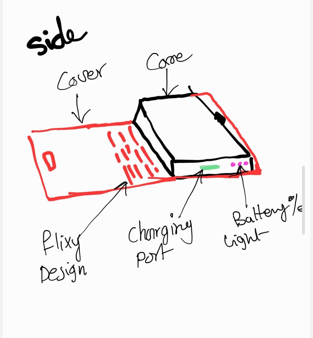
14 | The charging case will be small and flat enough to fit into a bag.
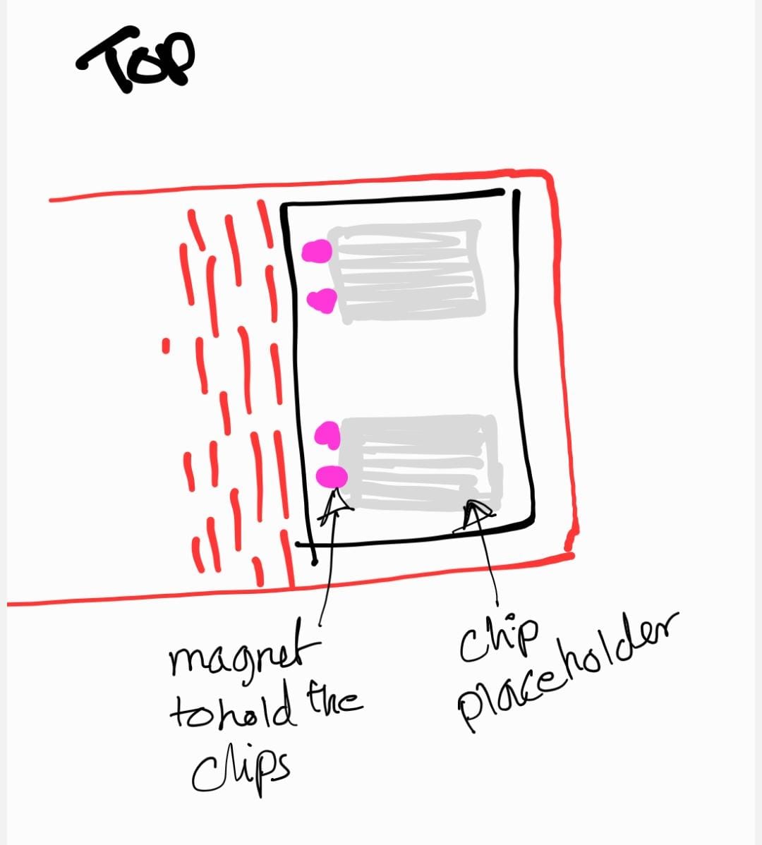
15 | The case has shaped placeholders for the clips to drop into.
16 | The case should hold all the parts and accessories together — clips, charging cable, spare battery.
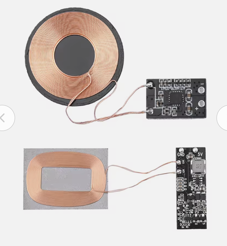
17 | Candidate wireless-charging coil — earmarked for the second spiral of the project.
- Feedback: On day one I was very fond of the full-harness vest idea and really wanted to finish it in time to wear it for the WRO Kuwait Finals scheduled in May. Watching that idea simplify — from harness, to strap, to a pair of universal clips — was one of the most interesting parts of the academy for me.
- Challenge: I felt the pressure in both the documentation and the time-management side of the course. Finishing the course became the priority, and having a project I could actually implement, fabricate, and document became more important than the most ambitious version of it.
01: Assembly-plan workflow — DFM (Design for Manufacturing)
Each subsystem has its own assembly workflow. QA = Quality Assurance (defect prevention — designing so problems can't happen). QC = Quality Control (defect detection — testing the result against spec).
Shoulder Clips (×2):
Update PCB design in KiCad →
mill PCB on FR1 (or vinyl-cut copper tape — see W08) →
solder the ESP32-C3, MPU6050, RGB LED, transistor, and passives →
QC: multimeter continuity check for short circuits + correct trace routing →
flash MicroPython firmware →
QA: bench-test on external 5 V supply (not battery) so any short fails safely →
solder the rechargeable LiPo via the TP4056 module →
QC: confirm functionality + estimate charging duration →
route the wires and fit components into the 3D-printed clip case →
pair to the app + run the end-to-end calibration / threshold / alert loop.
Wireless Charging Case (next spiral):
Define the wireless-charging coil + Qi receiver IC for each clip →
design the receiver PCB and integrate with the existing TP4056 charging path →
mill and solder the receiver coils →
QC: continuity + voltage check on the receiver →
laser-cut the MDF outer case with the living hinge (see W03 — Trial 03) →
fit the transmitter coil into a pocket aligned with the clip socket →
QA: alignment jig so the receiver always sits over the transmitter →
test charge time and end-of-charge cut-off.
Interface App:
Update the App Inventor designer (sliders, ListPicker, status labels) — see W14 →
update the block code (BLE pairing, calibration command, threshold push) — see W16 →
QA: name every component L_* / R_* so left / right blocks never get mixed up →
test in the App Inventor Companion with the clip on a power bank →
QC: confirm calibration round-trip (app → clip → app status) →
build the .apk and side-load to the phone →
QC: confirm the app keeps the BLE link alive when the phone screen is off.
01b: DFM — joinery, wire routing, and surface finish
Three Design-for-Manufacturing decisions I had to make explicitly while designing the clip case:
| DFM concern | Option I picked | Why |
|---|---|---|
| Joining the two halves of the clip case |
Magnets + a printed snap lip on the lid (a printed flexure-style catch — no screws, no glue). | The case has to be openable for battery service. Adhesive (epoxy) would have sealed it shut. Threaded fasteners would have needed brass inserts plus screws — too much wall thickness for the 22 × 35 mm clip. A printed snap lip (flexure) plus a magnet pocket on each half gives me a serviceable, screwless join that prints in one piece. |
| Joining the carry case |
Living hinge (a flexure) on the MDF case lid, plus wood glue on the corner joints. | Living hinges in laser-cut MDF give a 100 %-printable / cuttable lid pivot — see the parametric design in Week 03 — Trial 03. Glue at the corners was an explicit trade-off: I'd prefer slot-and-tab joinery on the next revision (logged in Week 03's reflection) but the deadline didn't allow another cut iteration. |
| Wire routing inside the clip | Dedicated internal channels: MPU → I²C bus on the top side of the PCB; vibration motor → flying leads through a slot on the side wall; LiPo → a 2-pin JST on the rear wall. | The clip case design includes printed pillars and channels that hold the battery and route the motor / charging wires so they can't catch on the PCB or short to the copper. Step 06 of the design walkthrough shows the pillar spacing — sized so a slightly different battery still fits. |
| Surface finish | Clip case: as-printed PLA with a 0.16 mm layer height (no sanding). MDF case: bare engraved + scored, no varnish. | The clip touches skin / clothing so the finish has to be smooth. 0.16 mm layers give an acceptable "good enough" tactile finish without secondary operations. For the MDF carry case, the engraved label and exposed grain are the intended aesthetic — varnish would have masked the FabLab provenance. |
02: Assembly — 3D design of the clip case
Detailed-design walkthrough of the clip case:
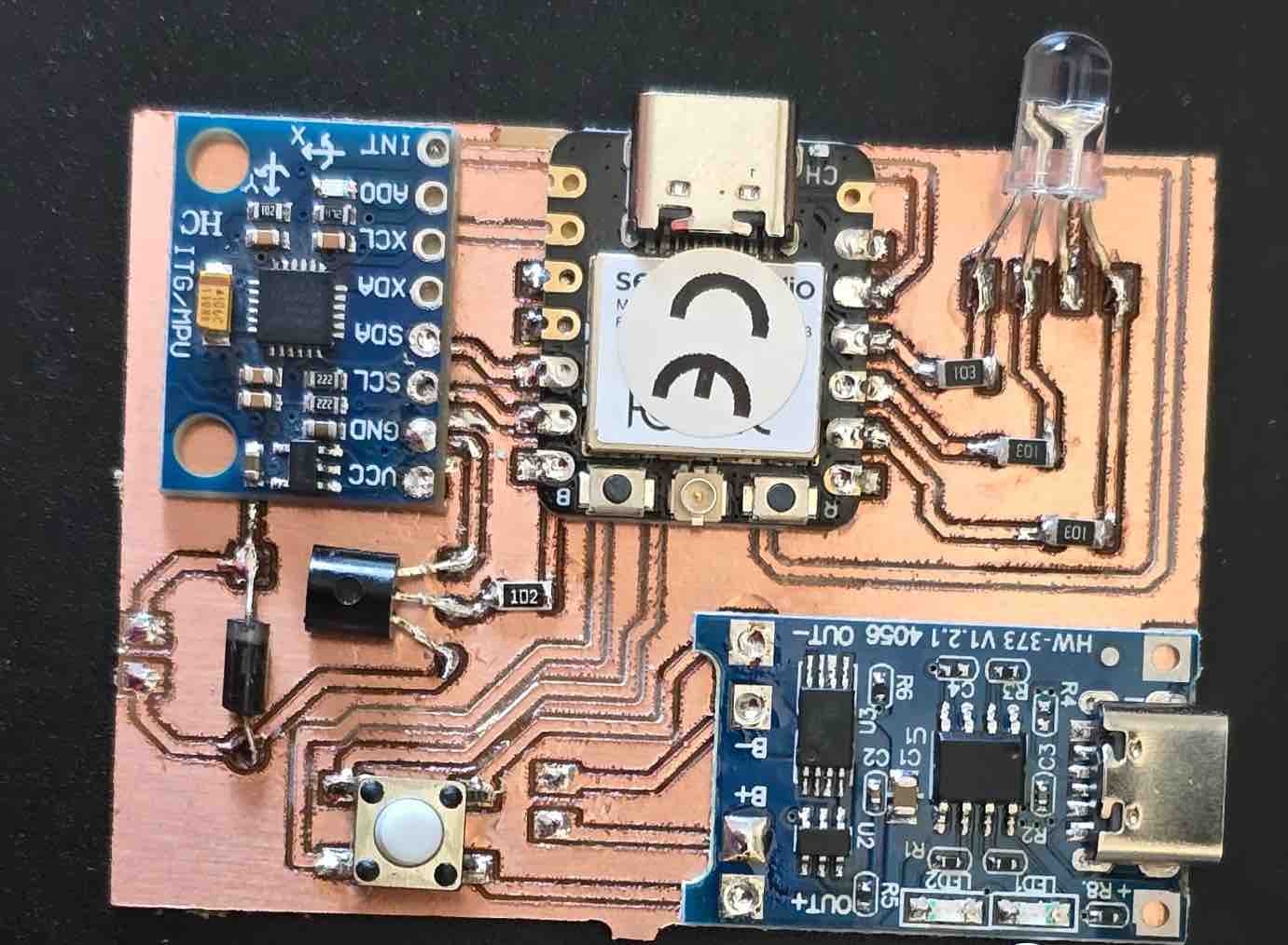
01 | All the PCB components were assembled in the most compact layout possible.
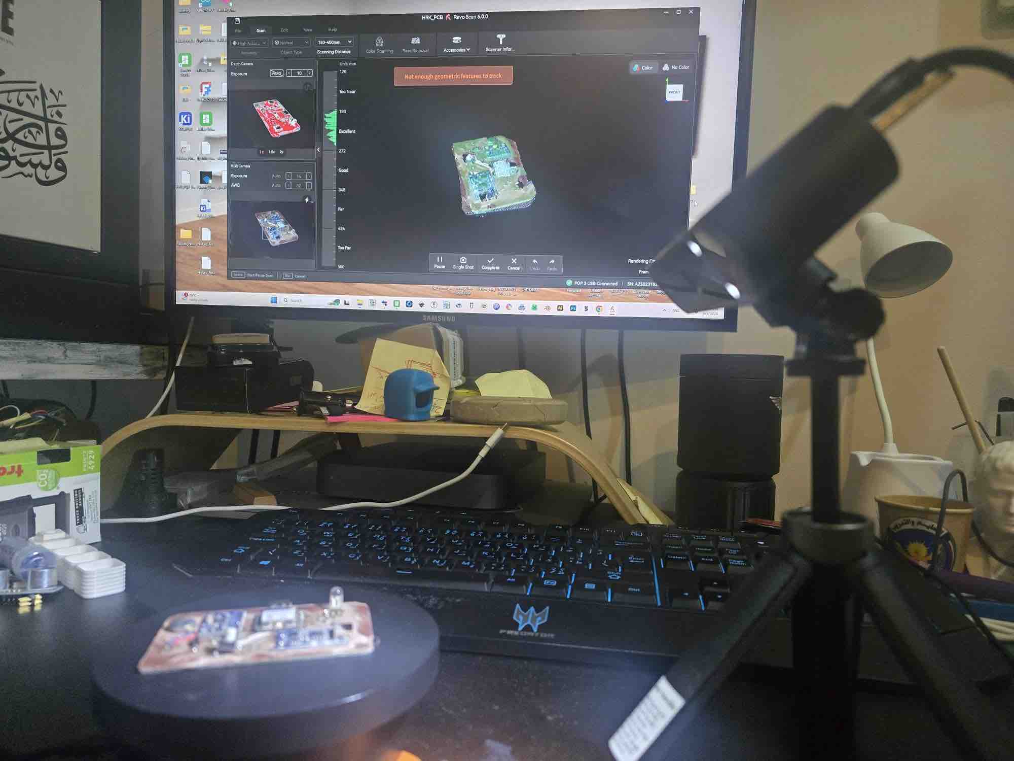
02 | After that, I tried to 3D-scan the board so I could use a real body in the case design and align the USB port and LED holes precisely. I couldn't get a clean enough scan for the case, so I fell back to measuring from CAD references.
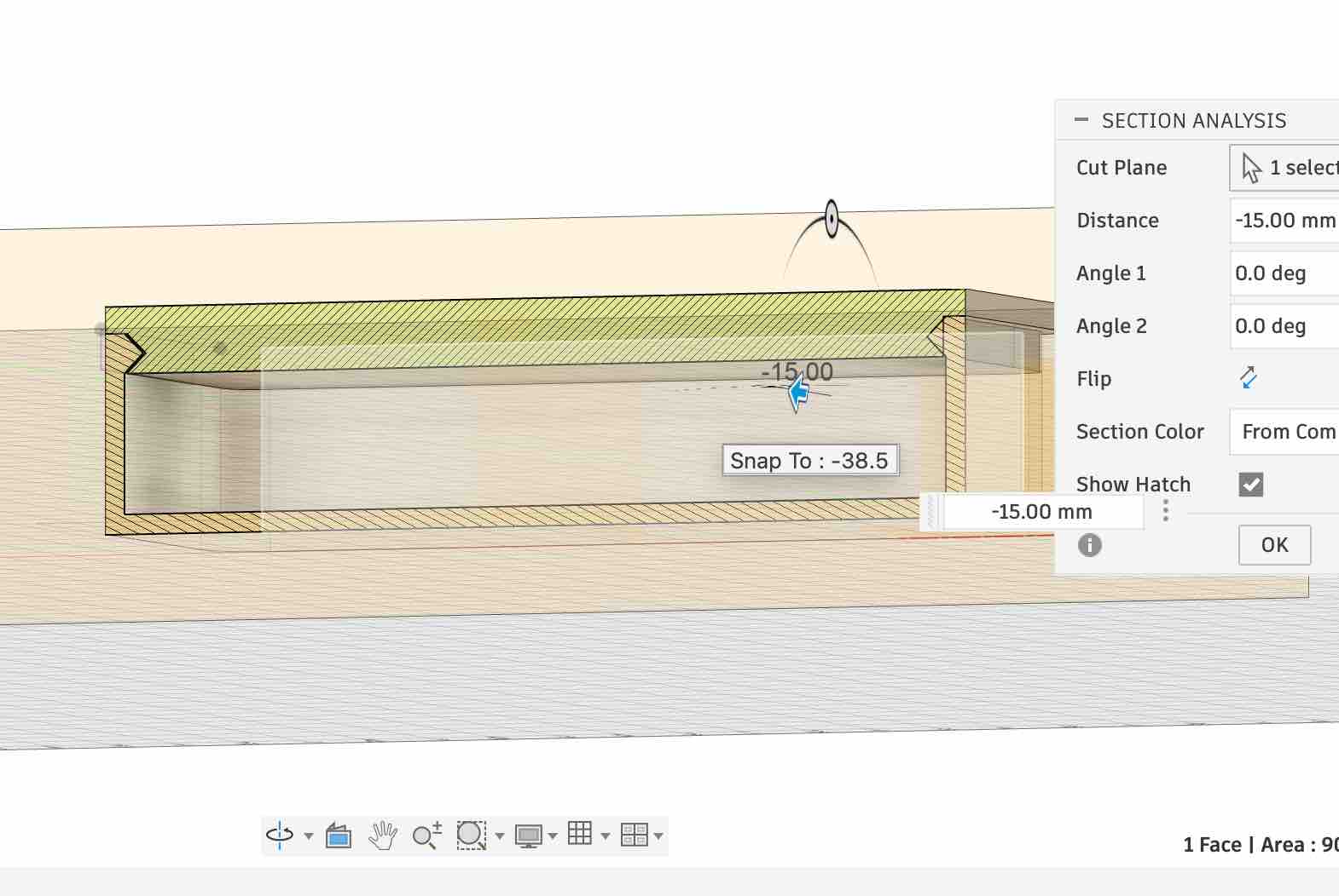
03 | I started by designing a parametric case with a snap-lip lid — a printed flexure that latches when closed but is easy to open again for servicing.
04 | I added pockets for the magnets, sized 1 mm larger than the magnet itself so the print would seat them without forcing.
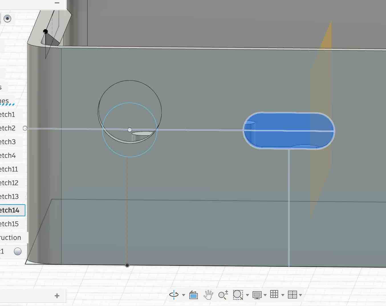
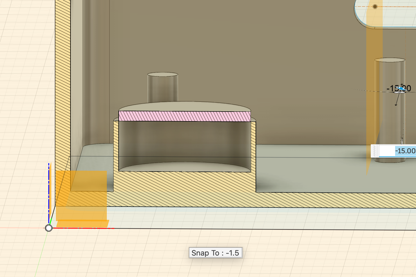
05 | I added holes for the USB port (so the case can be charged closed) and the LED (so the indicator is visible from outside). I drove these features off parametric constraints so the positions stay correct if I change the overall case dimensions.
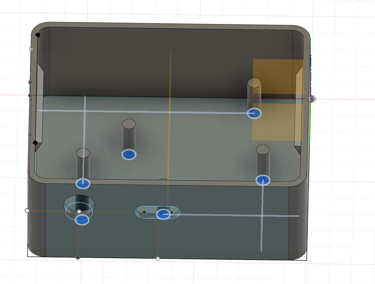
06 | I added small internal pillars to define wire routing channels and to hold the battery in place. One challenge that ran right up to the deadline: I couldn't source two batteries with the same dimensions, so the variable spacing between the pillars accommodates a range of LiPo sizes — important even at the end when each clip ended up with a different battery.
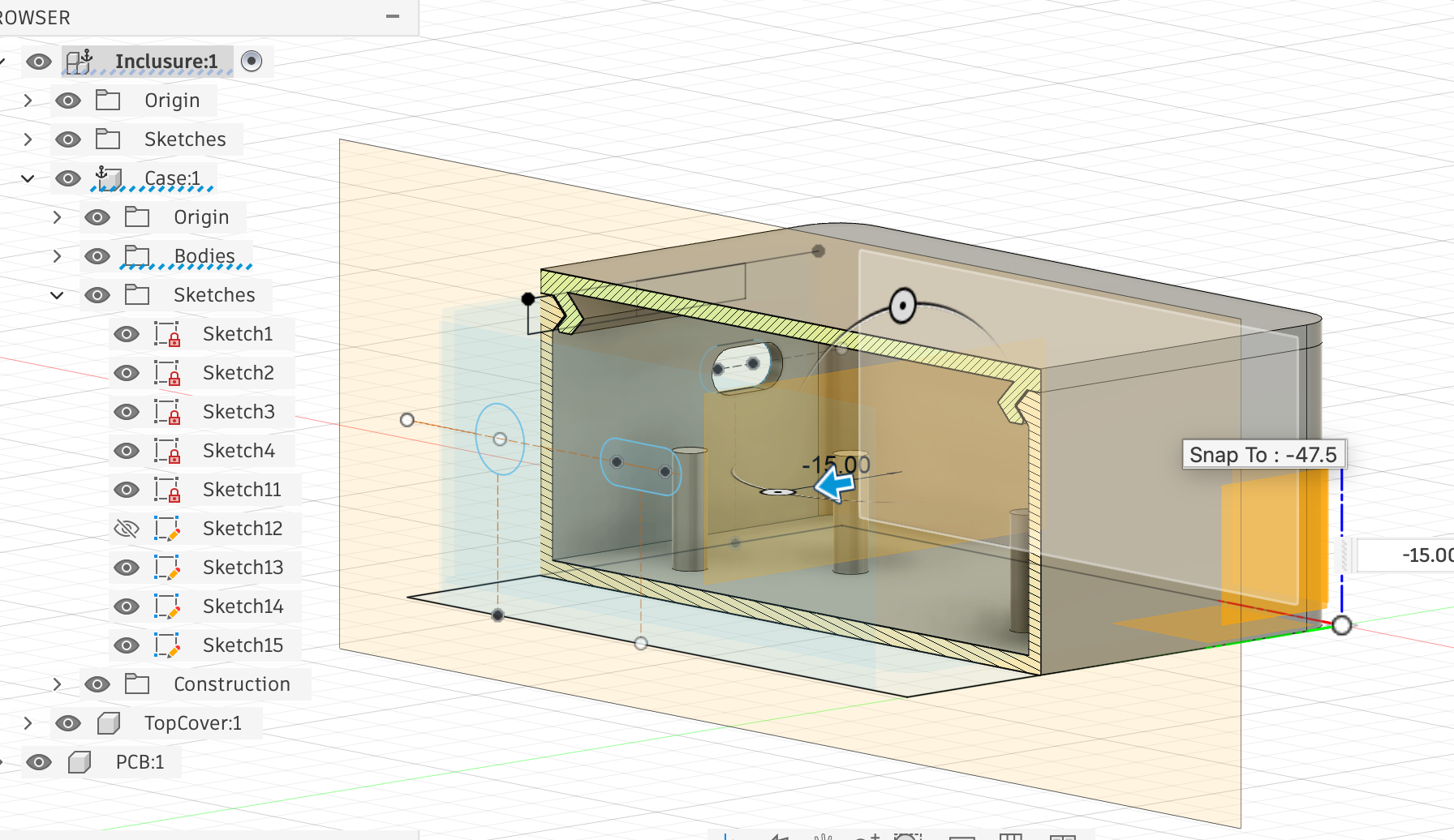
07 | After fixing the sizes I inspected every part of the design to make sure the components stay fixed in place while the clips are worn and the user is moving — the load case is wearable motion, not benchtop.
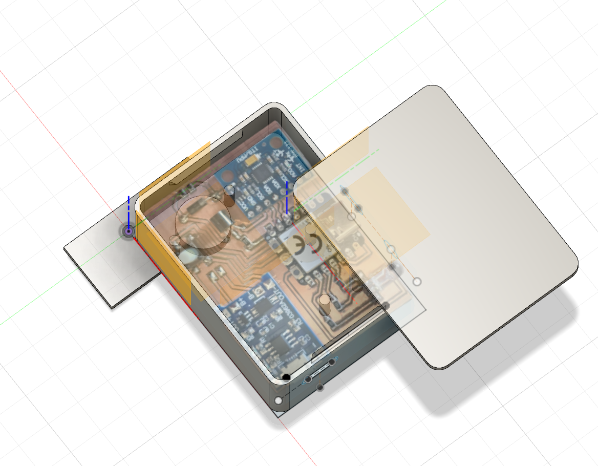
08 | Finally, I imported an image of the PCB, placed it in the case design and confirmed everything was accounted for. This is where I realised I needed the case ≈ 2 mm wider to leave a clean wire-routing path for the battery leads to reach the PCB.
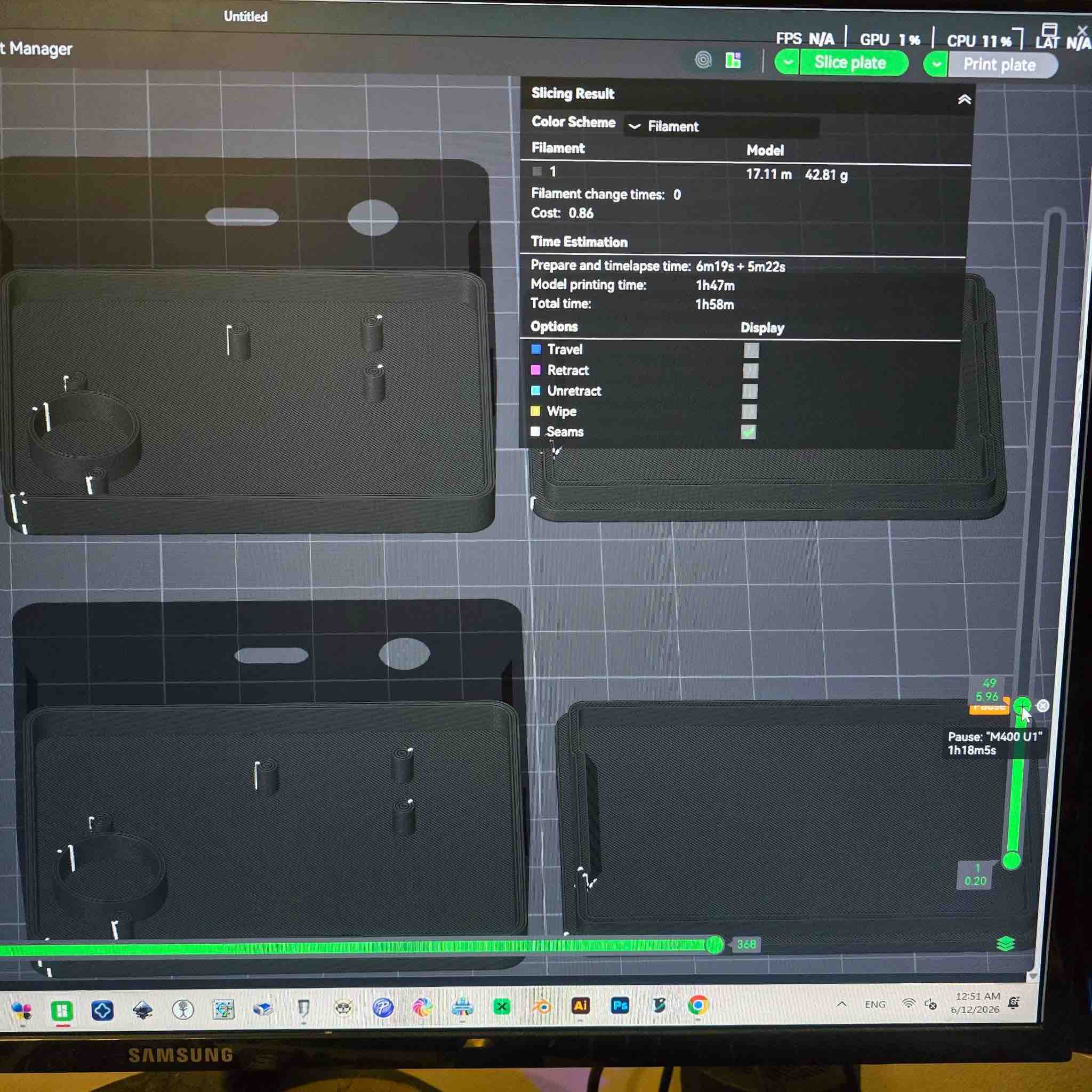
01 | The different bodies were organised, sliced, and ready for printing — the clip case, the lid, and the LED top piece. I also added a pause layer so the printer stops mid-print and I can drop the magnets into their pockets before the print closes over them. Then I initiated the print.
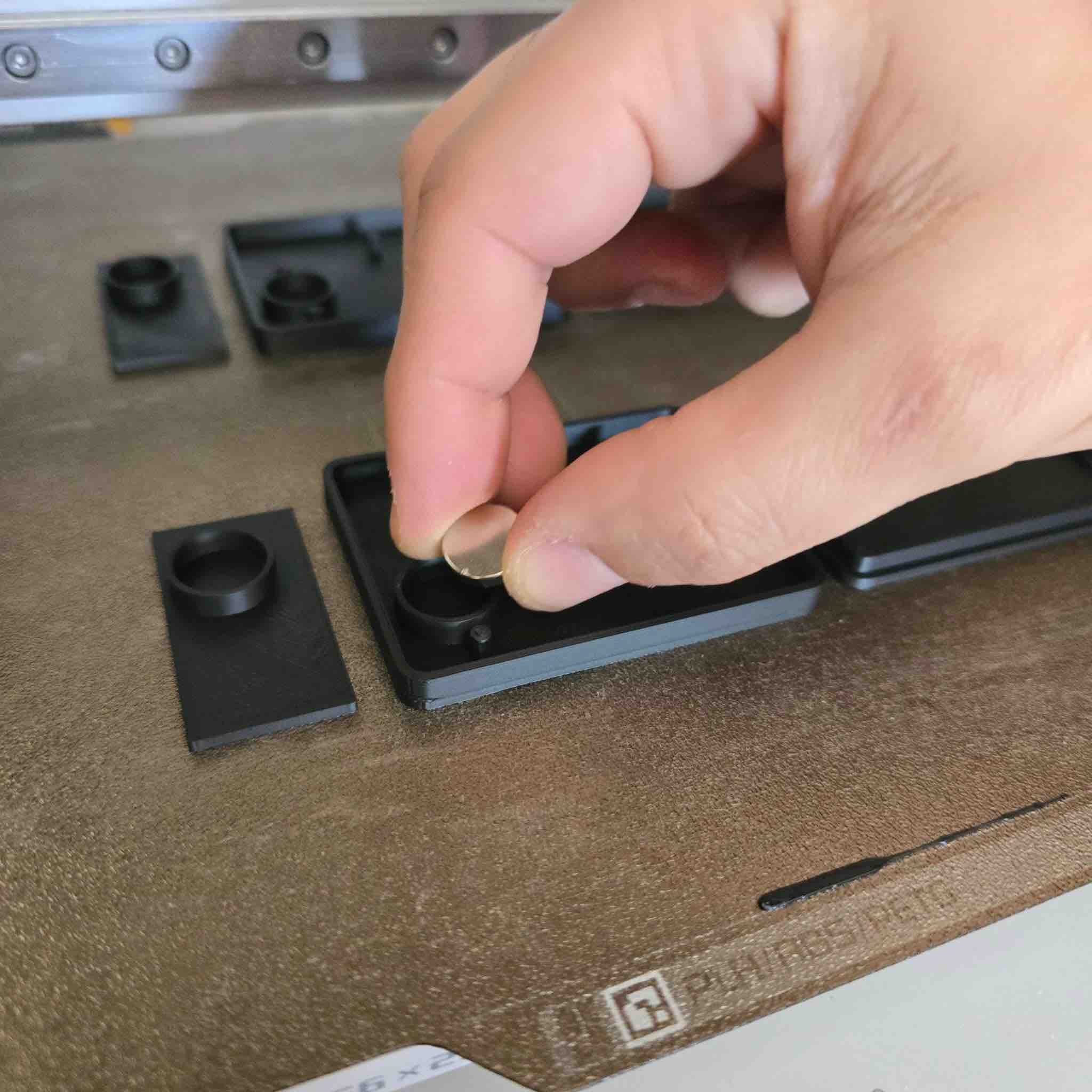
02 | This is where the printer paused and I dropped the magnets into the sockets — making sure I placed them so the attractive sides would face the carry-case magnets correctly. If I got the polarity wrong here, I'd have to break the case open to get the magnet out, so this was a high-stakes step.
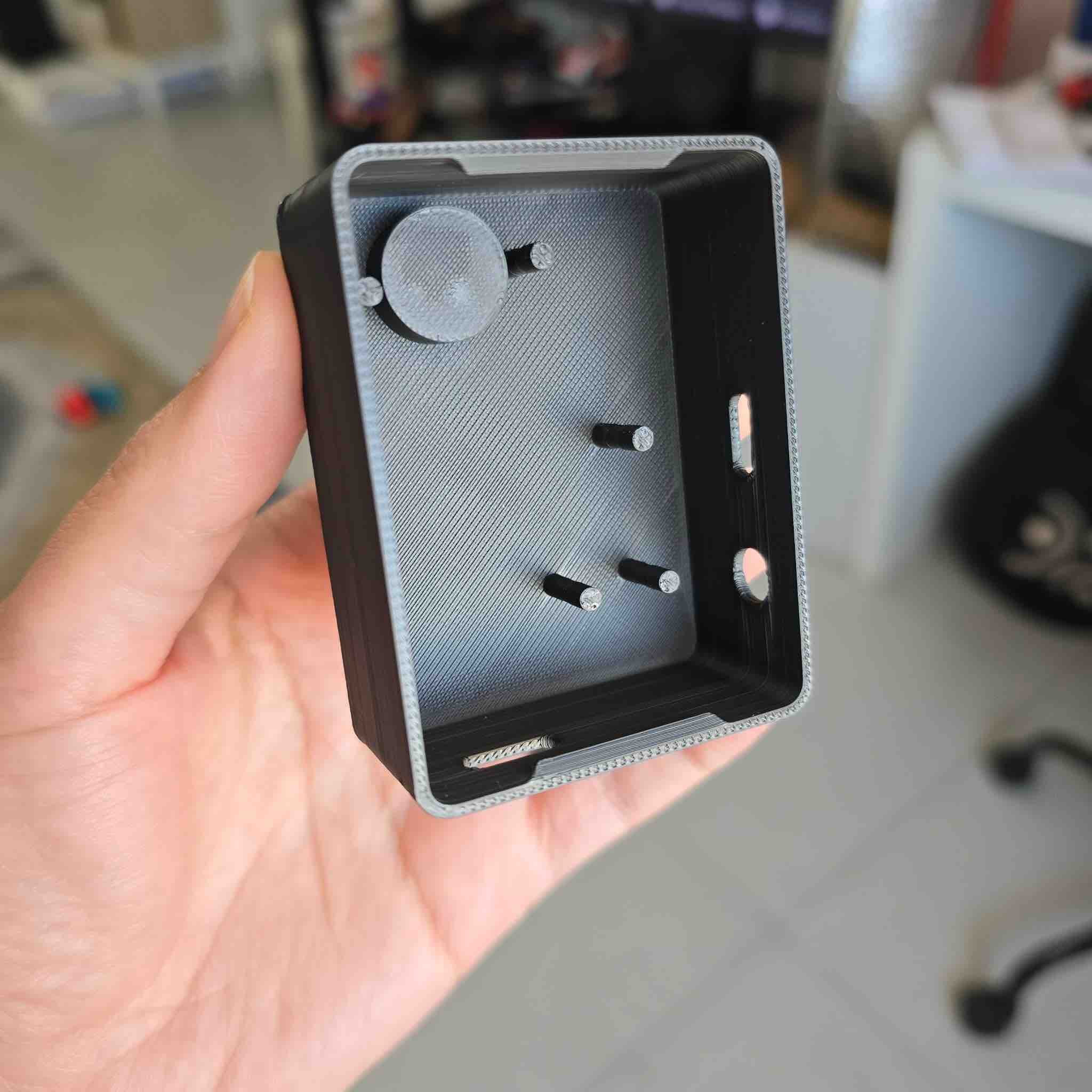
03 | This is the final result — looks clean and the holes seem aligned. Now it's time to test component fit.
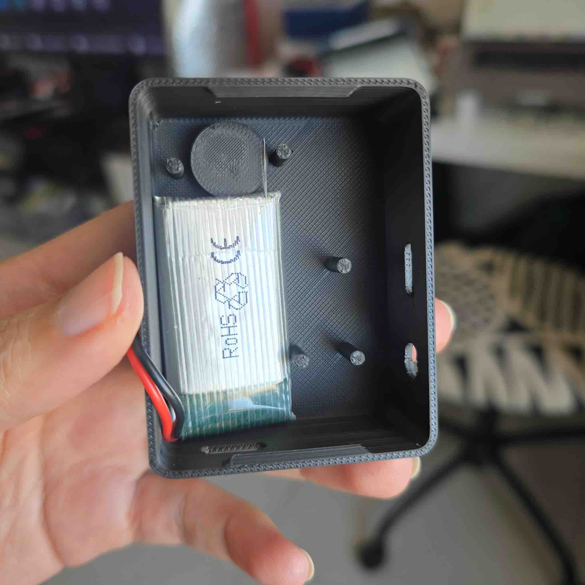
04 | First I tried fitting the different battery sizes I had and made sure they'd stay stable as the clip moves in different directions during wear.
05 | Then I imported the PCB and fitted the ports and LED into the designated spaces. One challenge with the LED: there was a slight difference between the LED position on each PCB. The LEDs were originally through-hole parts and I'd converted them to behave as SMDs by trimming the legs — and the trim lengths weren't identical, so the height varied between the two clips.
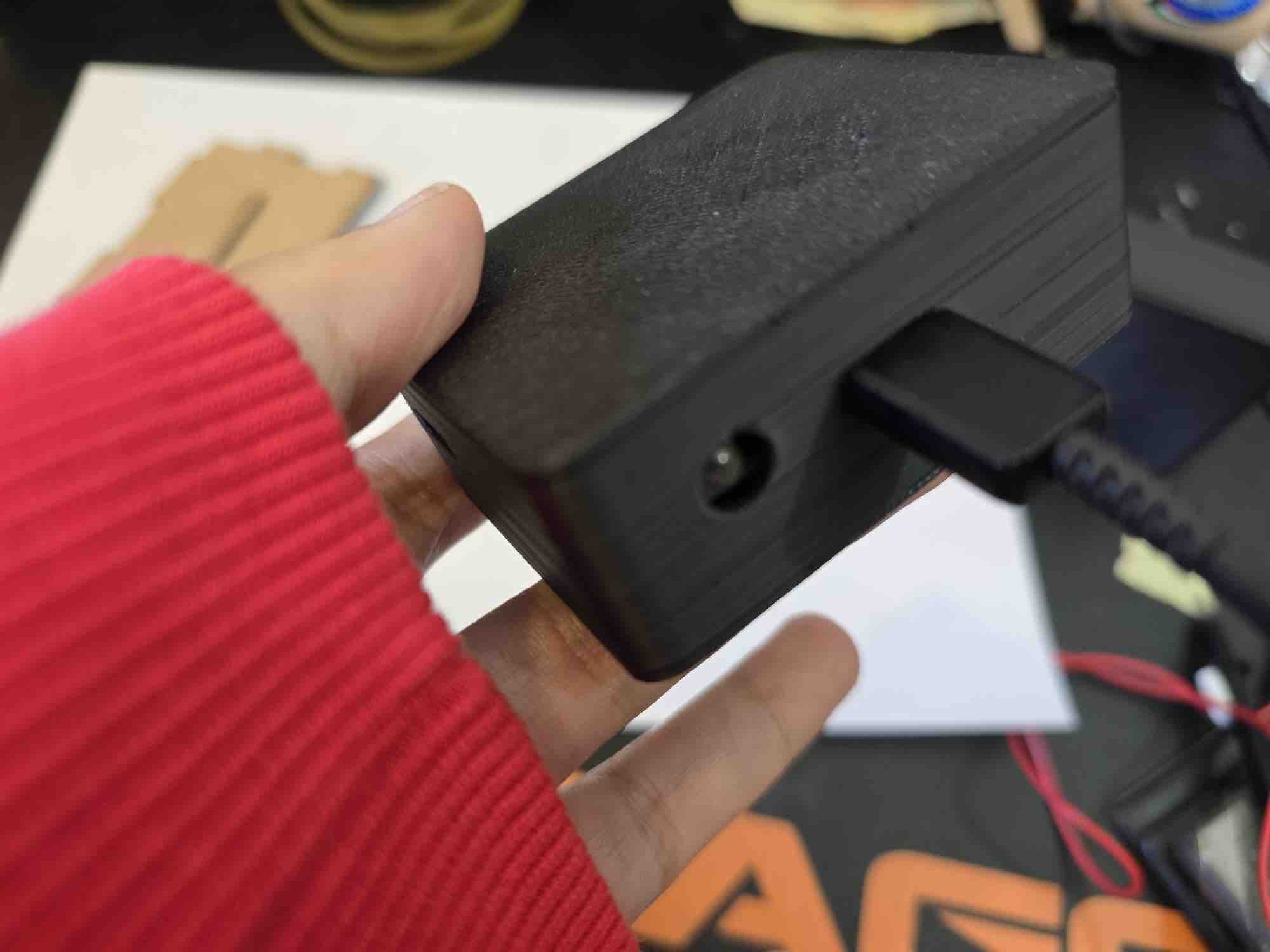
06 | For the USB ports I attached them to an external charging cable as a fit test — both size and position were correct.
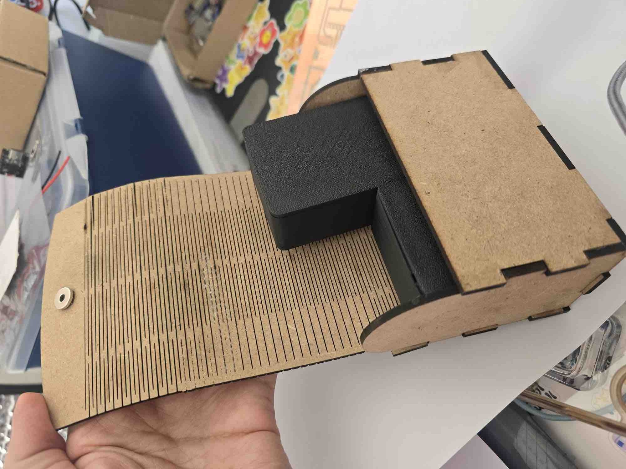
07 | Finally, after seating the components and closing the LED top, both clips fit into the laser-cut MDF carry case — with attention to small details. One clip had the LED protruding slightly from the case hole, which made the wooden carry case a little tight for both clips, so I had to realign them. Fixable on the next revision with proper SMD-package LEDs.
08 | Video of the final assembly inside the clip case while testing for connectivity and short circuits.
04: Testing — QA + QC + shake / drop / environmental / fuzzing
I tested continuously while I designed, built, and assembled — this was one of the areas I learned the most about in FabLab. With limited time and limited inventory, I did not have room for errors or for redoing things from scratch, which made phased testing critical in my workflow. I split the testing into the standard categories evaluators look for at integration time:
- QA — Quality Assurance (prevent defects): design rules that stop a class of failure from happening — naming conventions in App Inventor, alignment jigs, magnet pause-and-place layer, multi-meter-before-power policy, off-board flashing.
- QC — Quality Control (detect defects): continuity / multimeter check after every solder session, fit-test after every print, BLE round-trip check after every firmware flash.
- Shake (vibration durability): clip is shaken vigorously to confirm components stay seated under normal wear loads.
- Drop (impact durability): clip dropped from 1 m onto a hard floor — the worst real-world fall it'll see.
- Environmental: realistic wear conditions — body heat, sweat, ambient humidity, indoor / outdoor temperature swings.
- Fuzzing (malformed-input resilience): send unexpected BLE payloads from the app to check the clip's firmware doesn't crash or wedge on bad strings.
| Test category | Question | Findings |
|---|---|---|
| Shake | How durable are the clips when shaken hard? | Everything stays in place. I can only hear the magnets rattling slightly in their chambers — for this revision, that was a pass. |
| Drop | How durable is the clip case when dropped from 1 m onto a hard floor? | The 3D-printed clip case itself was durable. However, the MPU6050 separated from the PCB on impact — a clear sign the soldering wasn't strong enough on the through-hole-to-SMD conversion. I had also covered unused MPU pins with tape to avoid shorts against the dense PCB routes, which made the joint mechanically weaker. The vibration motor also moved from its glued position — in the next spiral, I'd add a printed pocket on the underside of the PCB to mechanically retain it instead of relying on adhesive. |
| QC (functional) | What is the lowest vibration strength the wearer can feel? | I could feel down to ~10 % strength when the clip was worn. Incident found by accident: when I left the motor at 100 % continuously during app calibration, the motor wire fatigued and broke because the motor wasn't fixed to a surface and was free to vibrate against itself — strong evidence for the mechanical retention point above. |
| QA (EMI / interference) | Do the case magnets affect the MPU sensor values? | Because I'm using the gyro + accelerometer outputs (not the magnetometer), the magnets had no measurable effect on the values I was reading. There's a related theory I didn't have time to test: the math from Week 14 converts the MPU's X/Y/Z deltas into values relative to earth's gravity, so even a magnetic disturbance would still be referenced to the gravity vector, not to magnetic north. |
| QC (charging) | How long does a full battery charge take? | Moved to the next spiral — this measurement is intended to characterise the wireless-charging-case efficiency, which isn't built yet. |
| QC (battery life) | How long can the clip run on one full charge? | I had different battery sizes per clip so I couldn't measure this directly. Calculated estimate, with the ESP32-C3 XIAO + MPU + RGB LED + vibration motor at 50 % strength continuously: (estimate to be filled in — depends on the final battery size chosen for each clip). |
| QC (BLE link) | How long does the app stay connected to the clip over BLE? | Moved to the second spiral. While the app was still in App Inventor Companion, the BLE connection dropped as soon as the phone went to sleep. The next step is to install the .apk on the phone and make sure the app keeps the BLE link alive in the background. |
| QA (magnet alignment) | Are the clip magnets aligned with the carry-case magnets? | In the design I made the magnet chambers fit precisely, and during the print I placed the magnets with the attractive faces oriented correctly — so the clips snap into the case the right way instead of repelling. Worked perfectly; the video also shows the magnet hold-strength through different fabric thicknesses. |
| Environmental — body heat / sweat | Does the clip behave the same when worn against warm, slightly sweaty skin? | Spot-tested for a 30-minute wear session: case stays cool to the touch, MPU readings drift < 0.05 g, no condensation. The PLA case isn't sealed though, so longer-term sweat ingress is an open question — flagged for the next revision (consider TPU gasket or a hydrophobic conformal coat on the PCB). |
| Environmental — ambient temperature | Does the clip work indoors AC (≈ 21 °C) and outdoors Kuwait summer (≈ 45 °C)? | Quick test: no observable behaviour change at 21 °C. At 45 °C I'm conservative — the LiPo is the weakest link (thermal protection above 60 °C). Full thermal characterisation moved to the next spiral; for now, "indoor use only" is the operating envelope. |
| Environmental — humidity / dust | Will the open case let dust or humidity into the PCB? | The current PLA case has the USB hole, the LED hole, and an air gap around the lid — so it's not sealed. For an IP-rated revision, the next steps are: switch the case material to PETG (less hygroscopic), add a TPU lid gasket, and apply conformal coat to the PCB except over the MPU breathing hole. |
| Fuzzing — BLE payload | Does the clip's firmware crash on malformed BLE input from the app? | I tested four malformed inputs from the app side: empty payload, a payload longer than the receive buffer, a payload with non-ASCII bytes, and a calibration command sent before BLE handshake completed. The firmware ignores the first three (the parsing block wraps the int / float conversion in try / except — see the Week 17 firmware listing). The fourth case (early command) was the one real bug found this week: the clip would lock the calibration flag without a baseline. Fixed by gating the calibration trigger on is_calibrated == False AND ble_connected == True. |
05: Implemented methods of packaging
The final project has three nested packaging layers, each addressing a different requirement:
| Layer | What it packages | Method | Material | Joinery | Surface finish |
|---|---|---|---|---|---|
| 1. PCB packaging | ESP32-C3 + MPU + RGB LED + transistor + passives | Milled FR1 PCB + vinyl-cut copper-tape PCB (W08 / W10) | FR1 / copper-tape on PLA support | Solder (lead-free), flux (RMA-223) | As-soldered, no conformal coat (yet) |
| 2. Clip case | PCB + battery + magnets + LED window | FDM 3D print on Bambu A1, parametric design in FreeCAD | PLA, 0.16 mm layers | Printed snap-lip lid (flexure) + pause-and-place magnets — no glue, no screws | As-printed PLA — no sanding, no varnish |
| 3. Carry case | Both clips, charging cable, spare battery | Laser-cut MDF with living hinges (W03 — Trial 03) | 2.8 mm MDF (140 × 60 × 75 mm) | Living hinge (flexure) for the lid; wood glue at the corner joints — to be replaced with slot-and-tab in the next revision | Engraved label (40 % power, 500 mm/s); cut (50 % power, 5 mm/s); bare wood, no varnish |
The three layers nest cleanly: the PCB sits inside the clip case which sits inside the carry case. Each layer's joinery method is chosen for serviceability (PCB: re-flowable; clip case: openable; carry case: portable) — none of them depends on adhesive as the primary holding mechanism, except the Week 03 carry-case corners (which I've already logged as a known issue for the next revision).
- Feedback: For the current phase, the clips passed the main tests. The biggest open item is improving the MPU solder joint — ideally by switching to a proper SMD MPU package that lives directly on the PCB instead of the through-hole-converted module I had to use.
- Challenge: System integration requires time and patience and I was up against the deadline, so I had to push the wireless-charging case, persistent-calibration, and battery-life characterisation into the next spiral — all while keeping the DFM constraint visible so future revisions stay manufacturable.