The process
This week is exciting and an area I wanted to learn more about in detail. I usually used microcontrollers for educational use — ones already built to make robotics and coding easy for K-12 children, who are our main stakeholders in the robotics education domain.
Microcontroller Comparison:
I am very new in this, so I asked FabGPT to help me in comparing between the list provided and the selection process
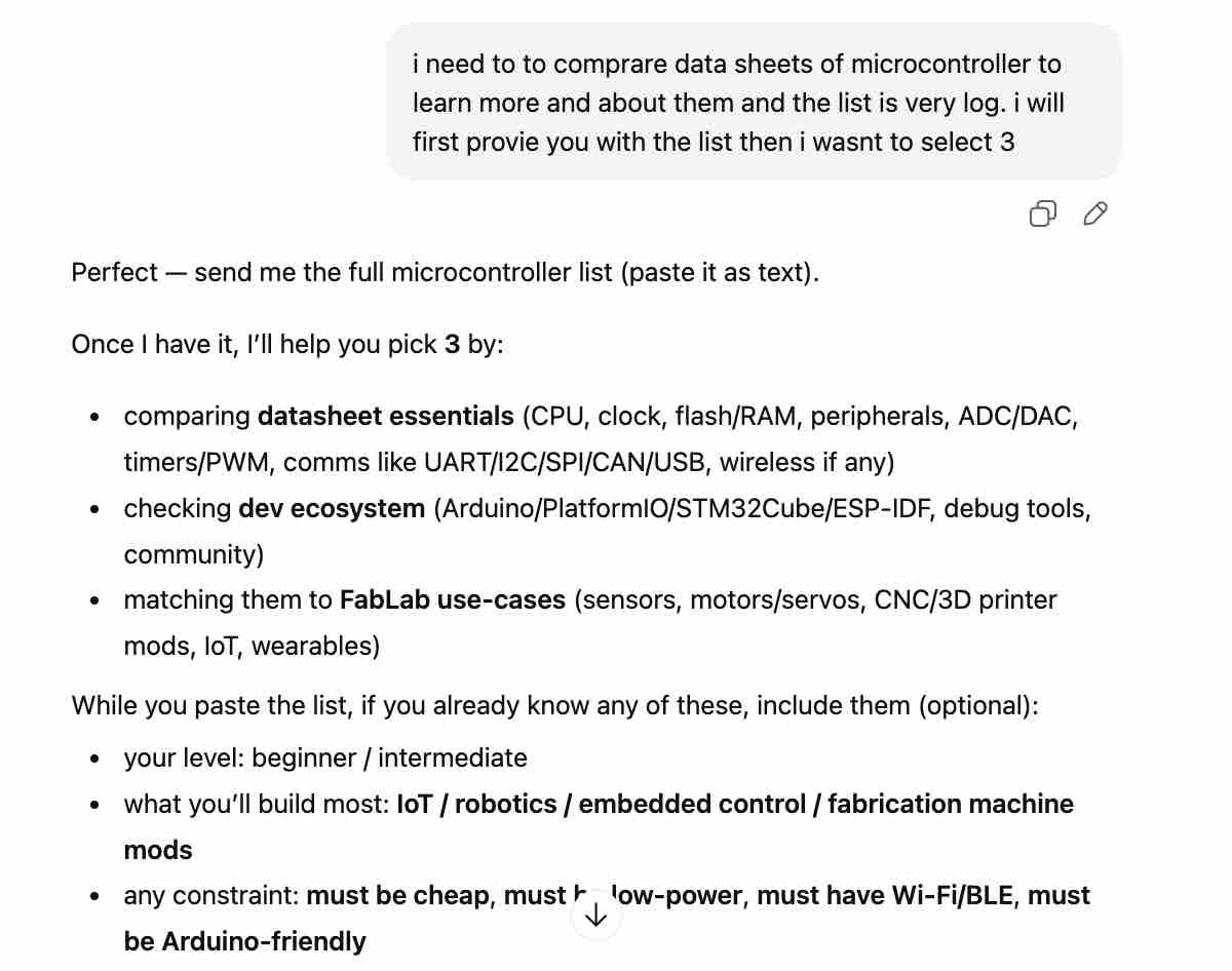
01 | I asked for help to compare and select a few to compare
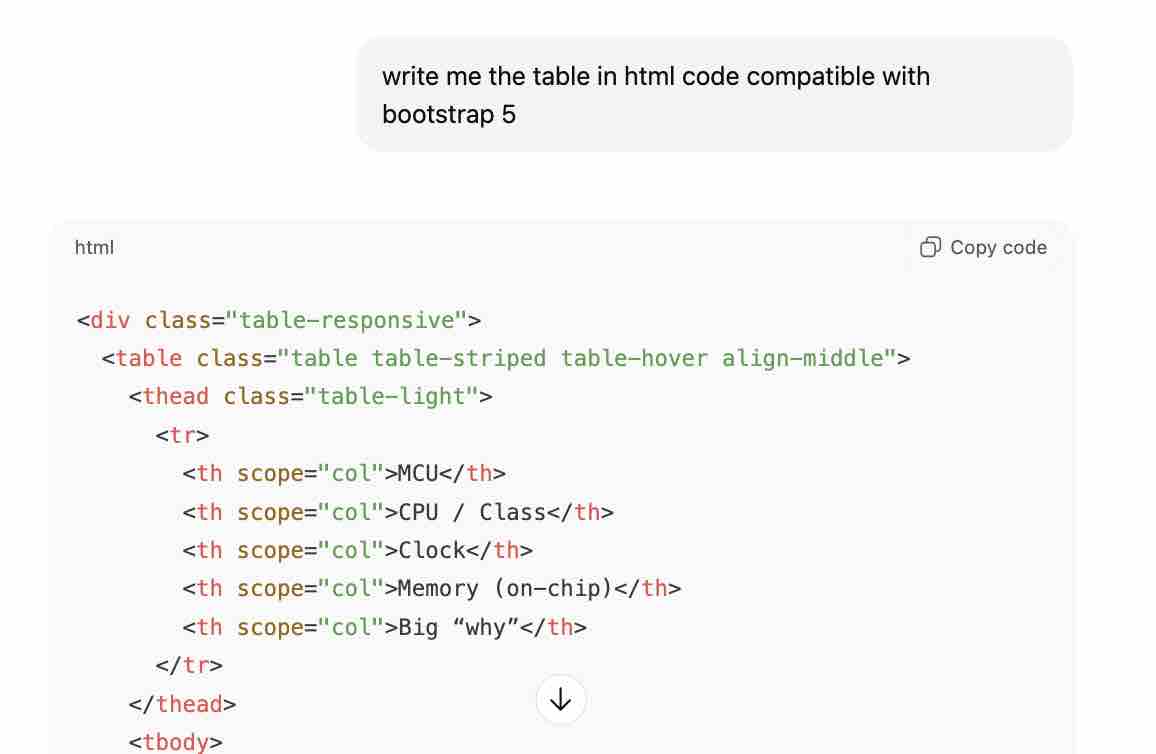
02| Asked for table with basic comparison before opening the data sheets
| MCU | CPU / Class | Clock | Memory (on-chip) | Big “why” |
|---|---|---|---|---|
| AVR128DB32 | 8-bit AVR | 24 MHz | 128KB Flash, 16KB SRAM | Best practical 8-bit mixed-signal + 5V friendliness |
| RP2040 | Dual-core Cortex-M0+ | up to 133 MHz | 264KB SRAM | Best for timing + learning 32-bit MCU structure |
| ESP32-C3 | RISC-V + Wi-Fi/BLE | up to 160 MHz | ~400KB SRAM (family) | Best entry to IoT + wireless MCU datasheets |
| ESP32-C6 | RISC-V + Wi-Fi 6/BLE/802.15.4 | up to 160 MHz | 512KB SRAM (noted by vendor) | Best for modern multiprotocol (Thread/Zigbee) |
- Feedback: I was interested to learn more about Raspberry Pi and ESP
Task 01: RP2040
01 | I opened the datasheet from this link
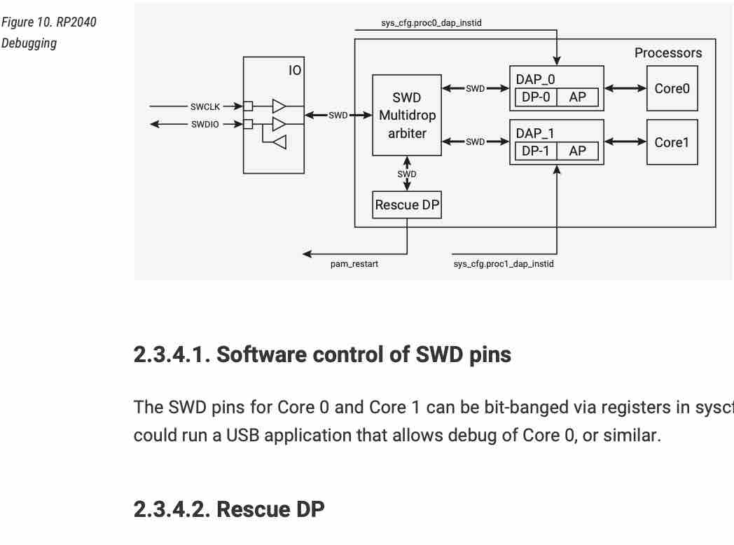
02| One main piece of information I saw: "Code may be executed directly from external memory" / "Debug is available via the SWD interface"
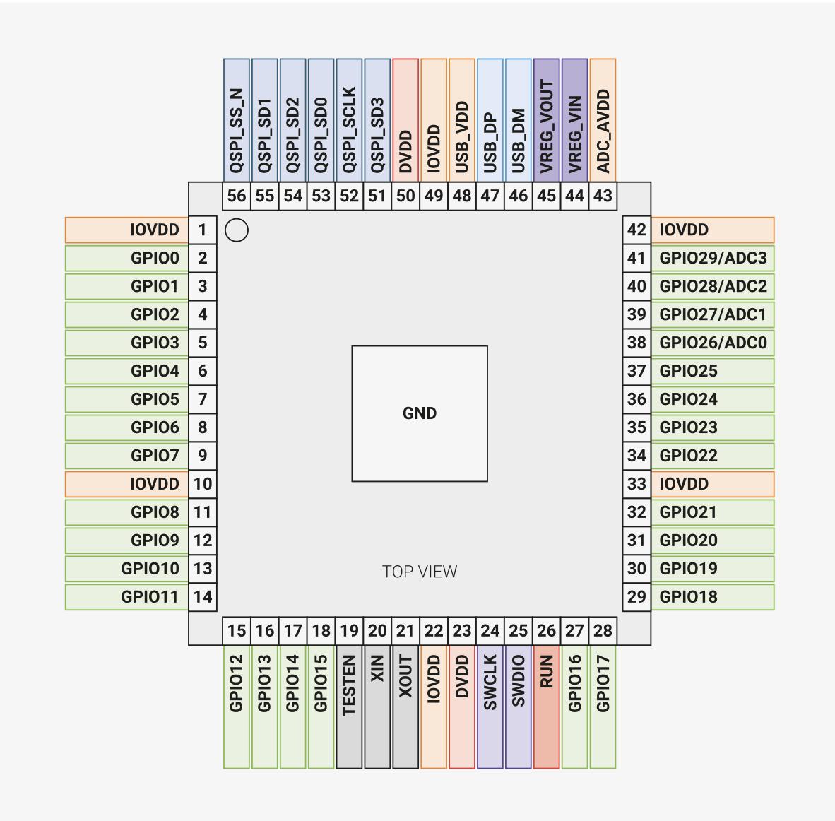
03| This diagram shows the pins available for connecting the other elements and devices
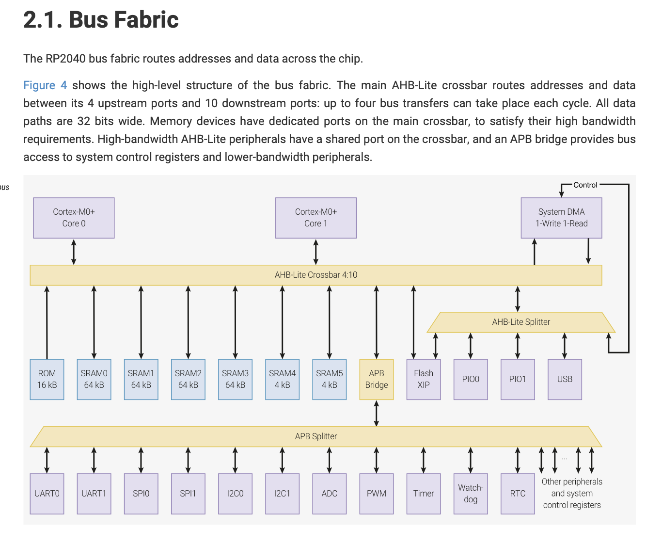
04| This sentence is in English but I did not understand what it means: "The four bus masters can access any four different crossbar ports simultaneously, the bus fabric does not add wait states to any AHB-Lite slave access."

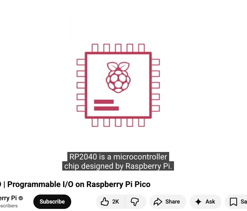
05| I looked on YouTube for a simple explanation and found this video
06| As I have limited time to allocate to this task, I searched for some explanation videos to make sure I understand the main concepts and that I'm ready for the next assignment from this link
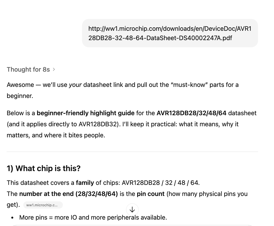
07| I also shared the datasheet with FabGPT to create a one-pager highlighting important information for a user with no experience
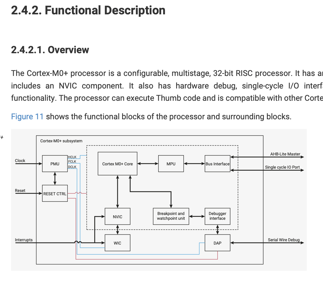
08| Functional diagram
09| and I asked to reference pages and section from the datasheet against each important information
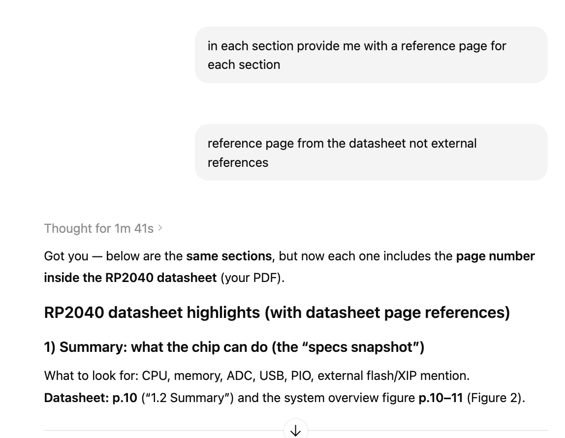
10| I looked in to Power Supply Schemes, Im still not sure how will this effect my desecion building the circuit
11| I looked into the different kinds of memories and tried to understand the differences
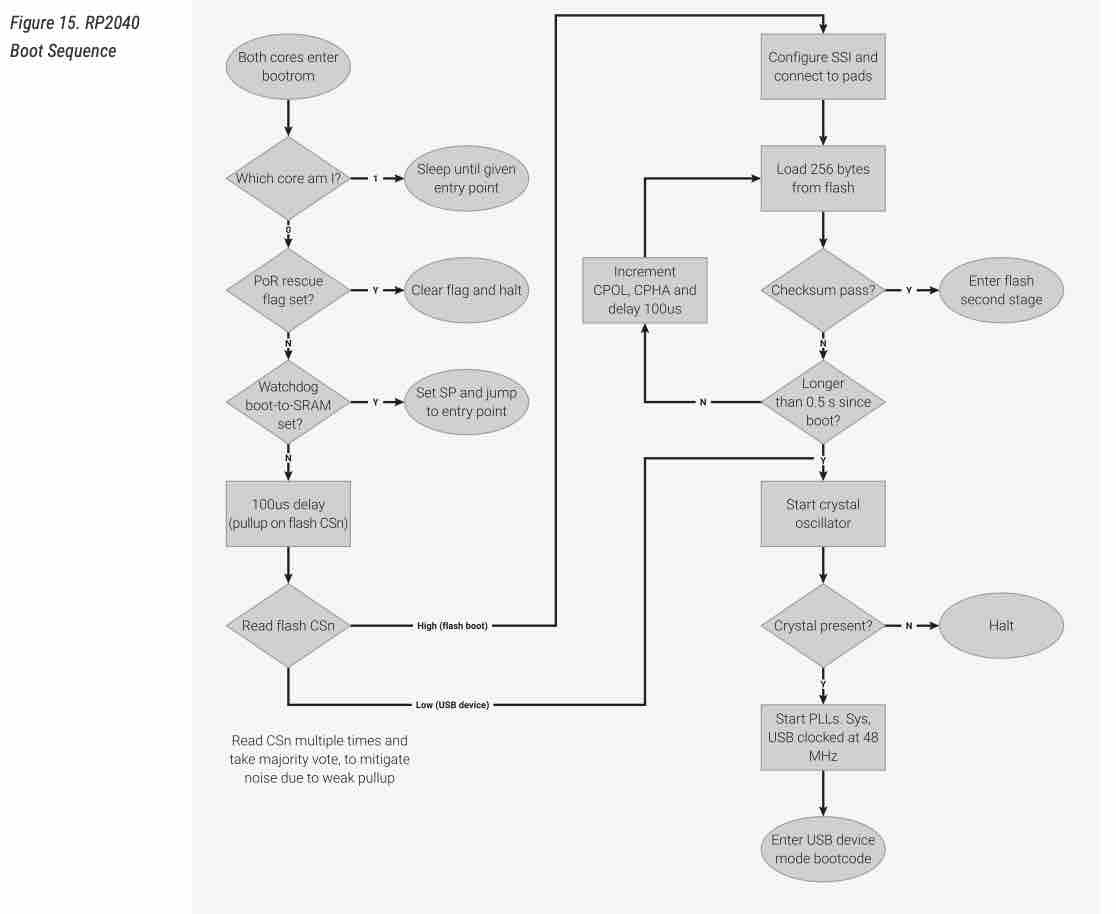
12| Processor Controlled Boot Sequence
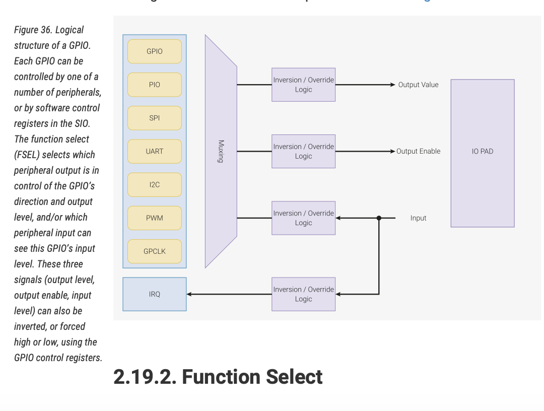
13| Logic and structure of the GPIO
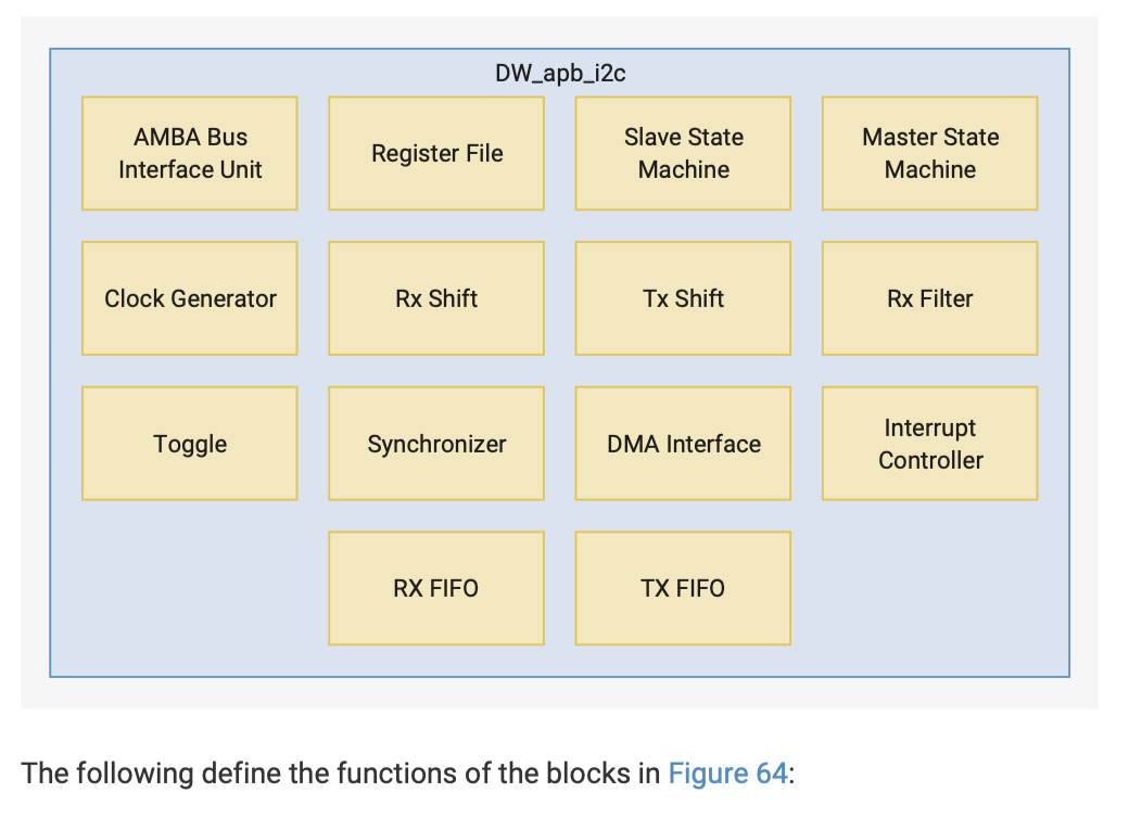
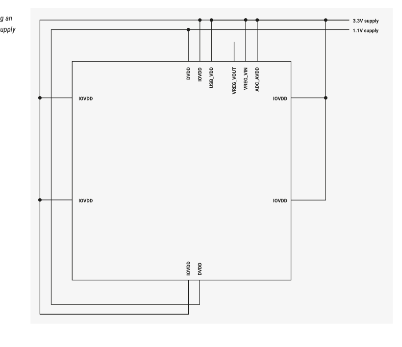
14| I found this block diagram, and the explanation on page 443 was a good summary of everything I read in this datasheet
- Feedback: I learned a lot and I think RP2040 would be a good choice for a more complicated project than the shoulder-guided posture fixture
- Challenge: It was not easy to understand the datasheet because I did not know many of the concepts and references mentioned
Programing Microcontroller:
Option 01: Building simple circuit

01 | I will be using the ESP32-C3 SuperMini for this task, as we have more pieces of this in our lab, and for my project I will need two microprocessors communicating
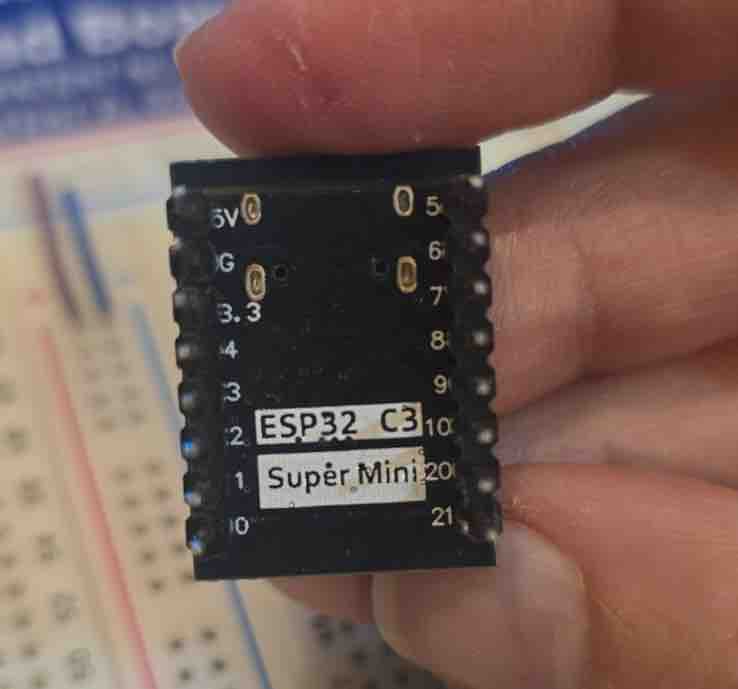
02 | It is small and I have enough GPIOs for my project
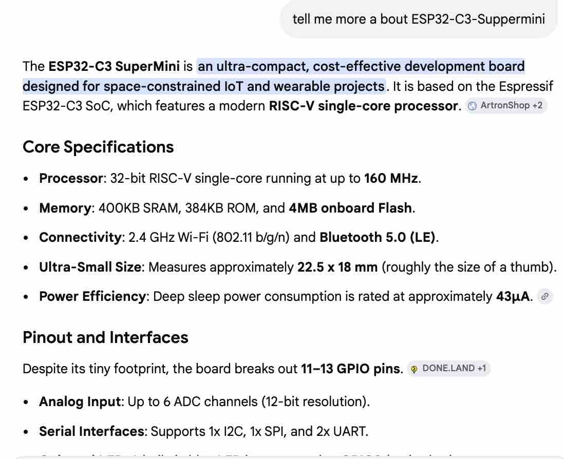
03 | I used AI Gemini to learn more about the microcontroller
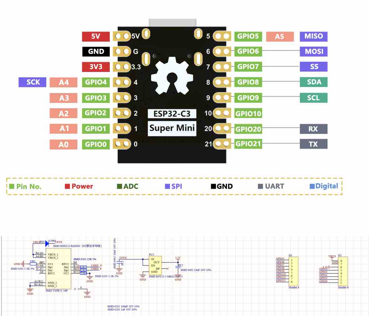
04 | I read the ESP32-C3 SuperMini datasheet to get more details
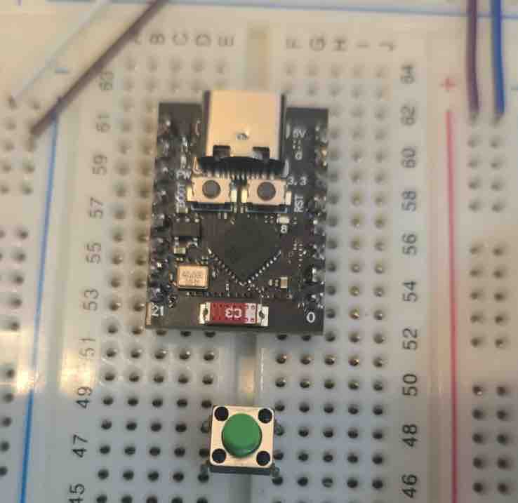
05| I connected the microcontroller to a breadboard and made sure I do not connect two pins on the same pin line to avoid short circuits. I also added a 4-leg button
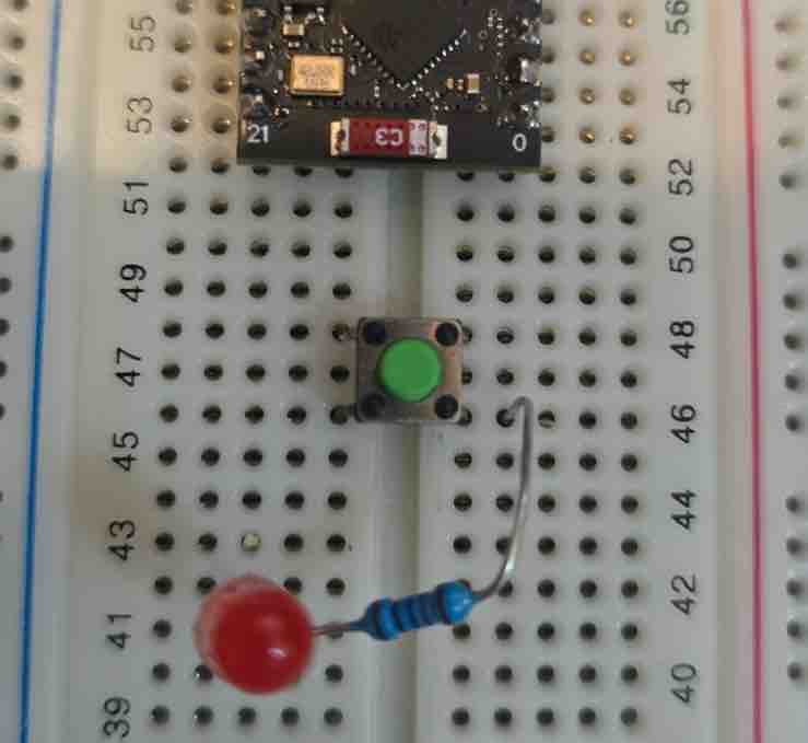
06| Then I added a LED light bulb and a 10K resistor.
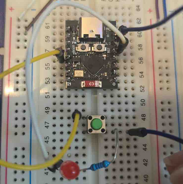
07| Then I used wire jumpers to connect my circuit.
Pin7 → LED → Resistor → GND
Pin9 → Button → GND. And as I'm documenting, I realized a huge mistake — the resistor should be connected before the LED, not after
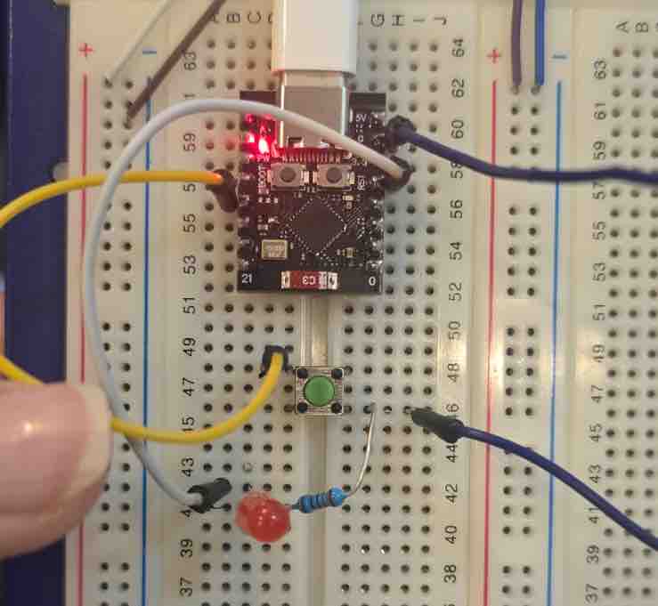
08| Then I connected the MC to the computer to start programming
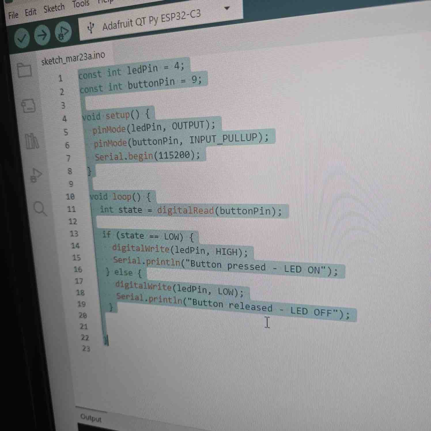
09| I used this code from a previous project in Arduino and downloaded the program to the MC
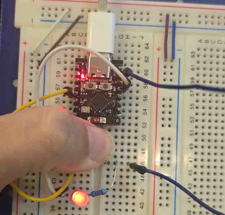
10| When pressing the button, the LED lights ON.
- Feedback: This was a simple circuit created fast to fulfill this assignment.
- Challenge: I misconnected the resistor and LED and came to know about the mistake while I was documenting. This showed the value of documentation in re-evaluating projects, as well as the importance of rechecking connections. Misplacing a resistor may result in damaging some parts.
Option 02: MicroPython
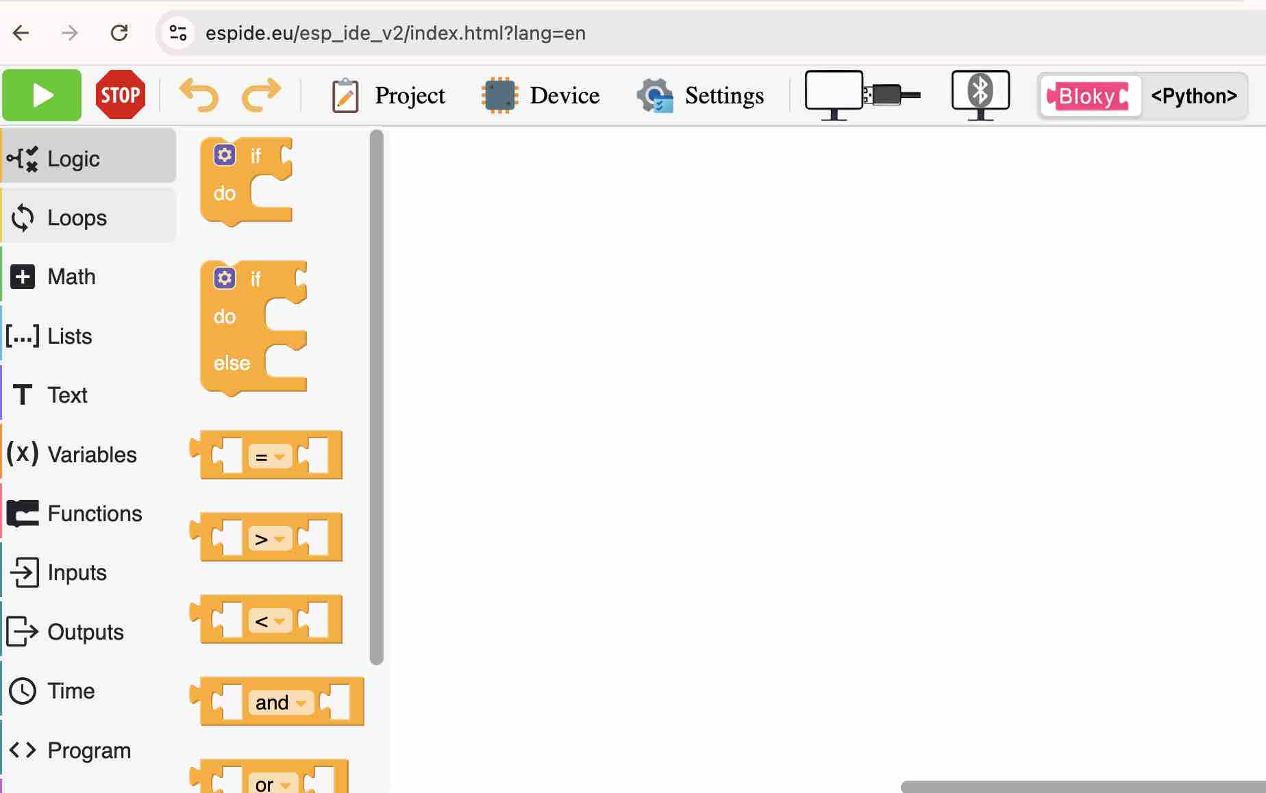
01| My first attempt was with ESP IDE — it includes a block-based coding view and a Python interface with USB and Bluetooth pairing
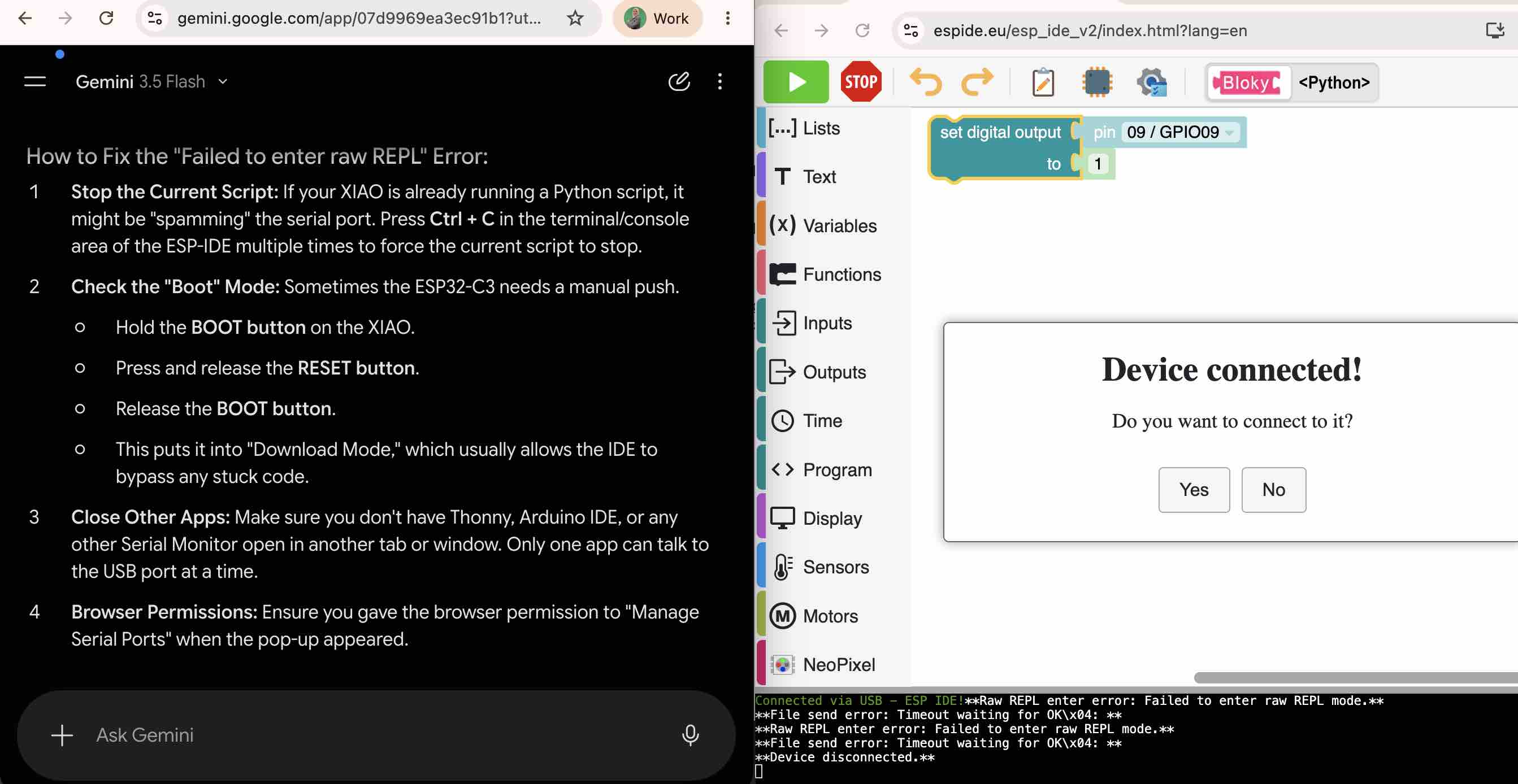
02| I tried to connect the ESP32-C3 XIAO to it, but the device wouldn't pair. I tried to troubleshoot with Gemini AI but couldn't get it working.
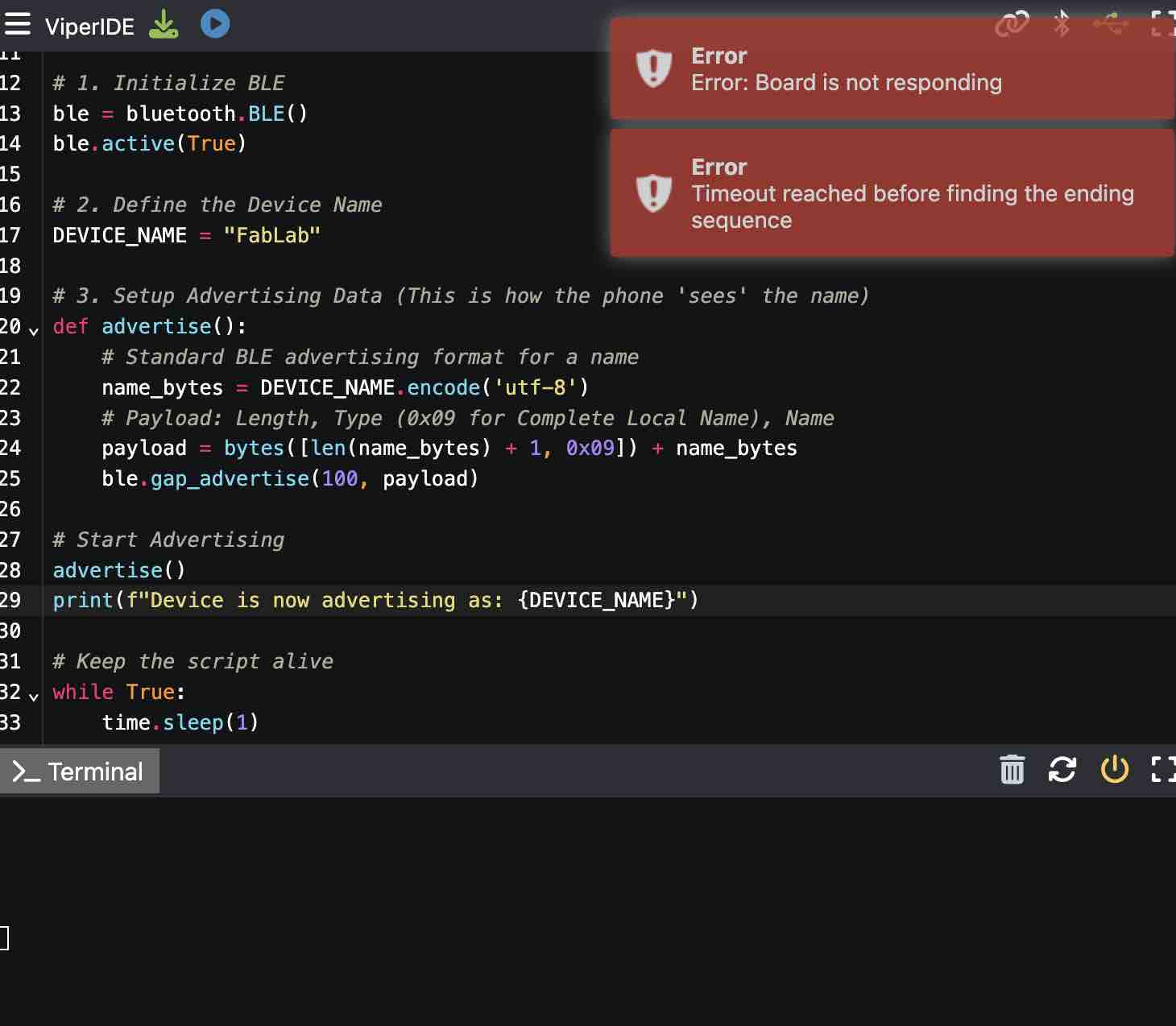
03| I moved to a second IDE, VIPER — I also tried to connect my ESP32-C3 XIAO but had difficulties.
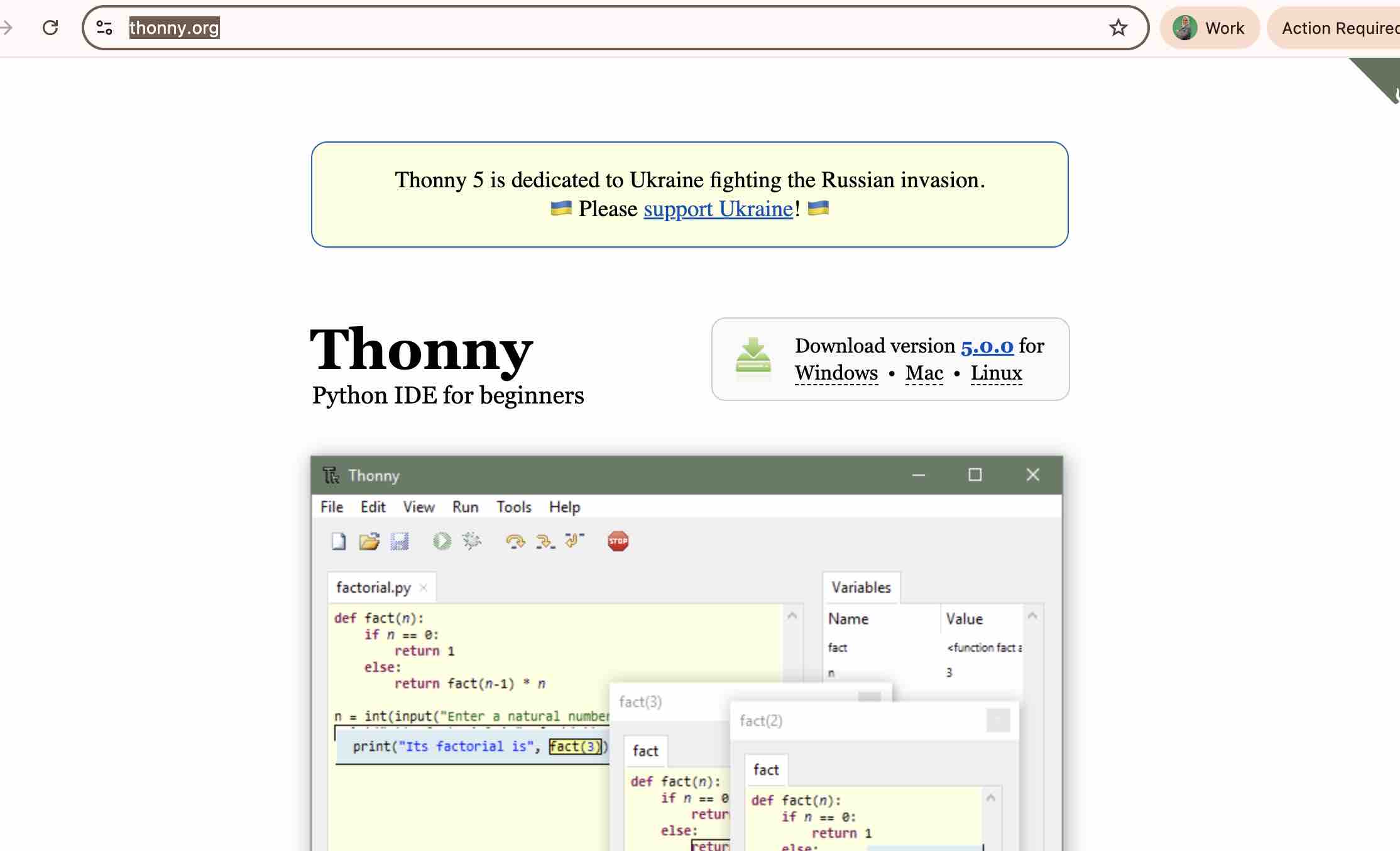
04| Then I tried Thonny — I first downloaded the desktop app.
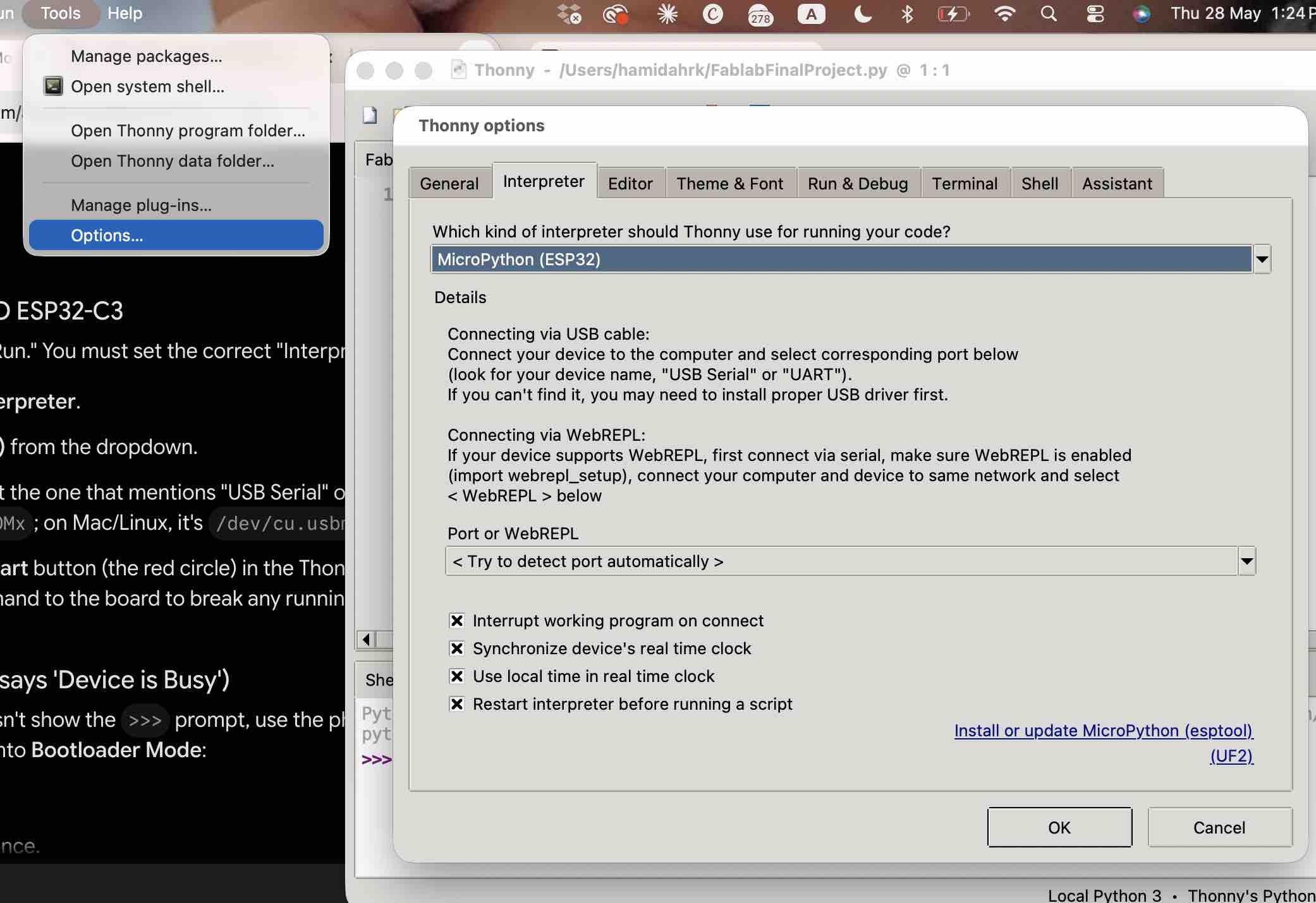
05| Setting up Thonny for the ESP32-C3 and making sure it was selecting the correct port.
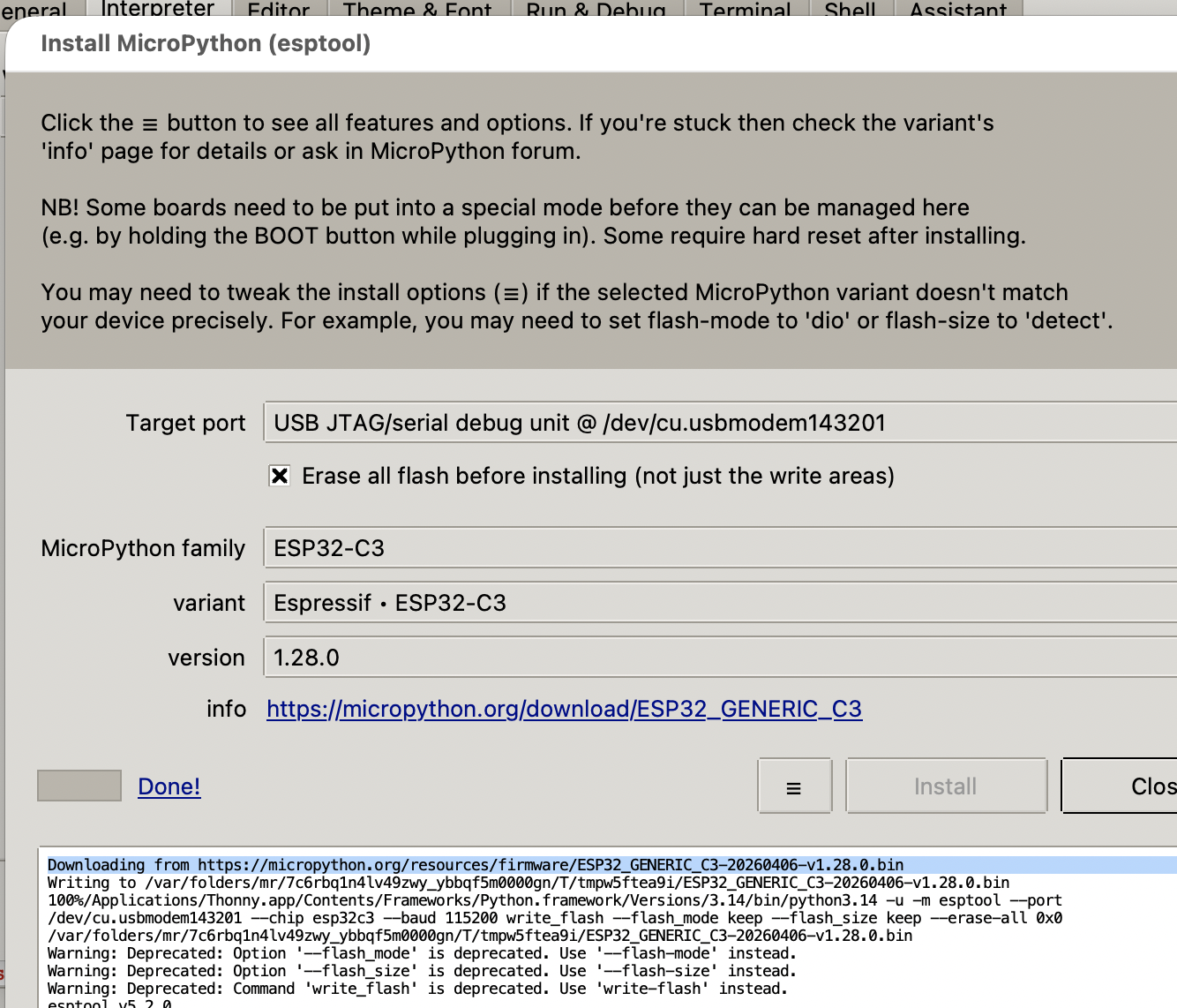
06| I found that I needed to flash the MicroPython firmware onto the microcontroller before sending any code.
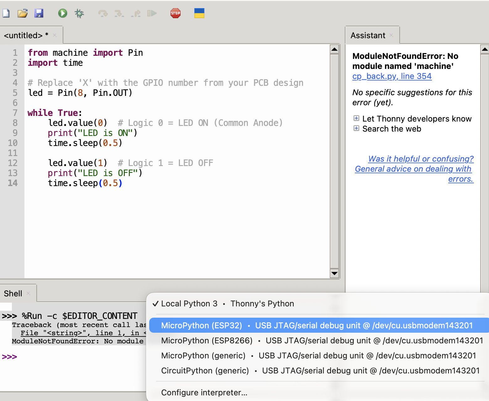
07| The interpreter also has to be switched over to MicroPython. the values used with GPIO was 0, for LED on and 1 for LED off becuase the LED used was a common Anode LED.
08| I tried a simple LED-blink sketch and it worked — this became the toolchain I used through the rest of Fab Academy and the final project.
# LED light blinking

from machine import Pin
import time

# Replace 'X' with the GPIO number from your PCB design
led = Pin(X, Pin.OUT)

while True:
    led.value(0)  # Logic 0 = LED ON (Common Anode)
    print("LED is ON")
    time.sleep(0.5)

    led.value(1)  # Logic 1 = LED OFF
    print("LED is OFF")
    time.sleep(0.5)
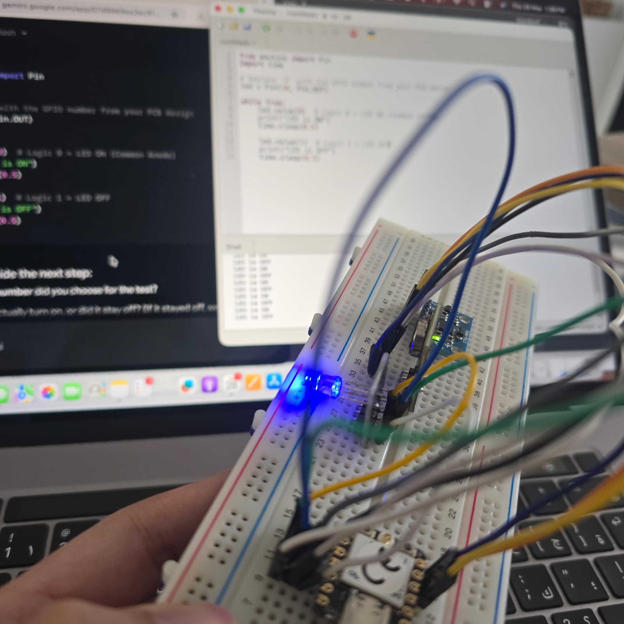
09| This is a video of the code used on PCB connected via USB type C cable to Thonny when uploading the same code to the microcontroller.
- Feedback: The online IDEs (ESP IDE, VIPER) wouldn't reliably pair with the XIAO over USB — a local toolchain (Thonny) ended up far more dependable. MicroPython is faster to read and iterate on; C++ feels more disciplined and may suit larger projects, but for a wearable prototype the REPL loop won.
- Challenge: Not a lot of time to pick up a new language, so I committed to MicroPython on Thonny and built fluency week by week — paying off in Week 09 — Input Devices (MPU6050 I²C) and Week 10 — Output Devices (RGB LED + vibration motor).