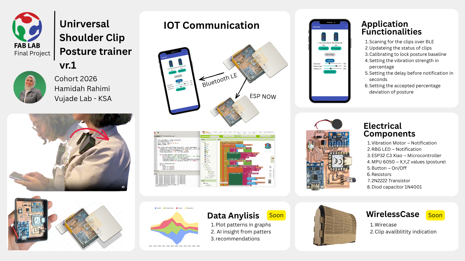
Problem
Long hours at a desk or lab can silently damage your posture. Poor alignment affects the spine and ribcage, causes certain muscles to become inactive while others are chronically overworked — leading to pain, discomfort, and long-term injury.
Solution
A lightweight wearable device that corrects posture in real time by tracking two fixed points on the shoulders. By monitoring shoulder alignment, the device guides the neck, back, and core into a healthier position — making good posture feel natural and comfortable. Over time, it trains the body-mind connection so correct posture becomes automatic.
Experience

As a 200-hour certified yoga instructor with a background in body mechanics and mobility anatomy, I understand posture from the inside out. Being part of the Fab Academy network gives me the tools to actually build this — and I'll be the very first one to wear it.
The following is the schedule I created when I came back to focus on Fab Academy, starting the 15th of May 2026. The main objective was to get the final project done, then use the remaining time to document and complete the assignments I had left behind. the last day in the calender is Jun 3rd 2026.
X represents the number of days in the week I worked on this task
| Task | W01 | W02 | W03 | W04 | W05 | W06 | W07 | W08 | W09 | W10 | W11 | W12 | W13 | W14 | W15 | W16 | W17 | W18 |
|---|---|---|---|---|---|---|---|---|---|---|---|---|---|---|---|---|---|---|
| 01| Ideation and Sketching | X | X | X | X | X | - | - | - | - | |||||||||
02| Electronic Production
|
XX | XXX | XXX | XXX | - | - | - | - | XX | XXXX | XXXX | XXXX | ||||||
03|01| Coding "Microcontroller"
|
XXX | XXX | XXX | - | - | - | - | XXX | XXX | XXX | ||||||||
03|02| Coding "App Interfce"
|
- | - | - | - | XXX | XXX | XXX | |||||||||||
04|02| Clips Packaging
|
XXX | - | - | - | - | |||||||||||||
04|03| Wooden Case
|
XXX | XXX | - | - | - | - | XXXX | |||||||||||
| Evaluation and testing | - | - | - | - | XX | XXXXX | XXXXX | XXXXX | ||||||||||
| Documentation | XXX | XXX | XXX | XX | XX | XX | X | XXXX | XXXX | XXX | - | - | - | - | XXX | XXXXX | XXXXX | XXXXX |

| Component | Function | Interface | Voltage | Notes |
|---|---|---|---|---|
| ESP32 Microcontroller | Main processing unit for sensor data and feedback logic | GPIO / I2C / Bluetooth | 3.3V | Handles posture calculations and communication |
| MPU6050 IMU Sensor | Detects tilt angle and posture orientation | I2C | 3.3V | Measures acceleration and rotation |
| Vibration Motor | Provides tactile alert when posture is incorrect | Digital Output | 3.3V / 5V | Activated after posture threshold exceeded |
| Status LED | Visual feedback indicator | GPIO | 3.3V | Shows system state |
| Rechargeable LiPo Battery | Portable power source | Direct Power | 3.7V | Enables wearable device operation |
| Charging Module | Battery charging and protection circuit | Power Management | 5V Input | Allows safe USB charging |
02|02|01| PCB Design
Create a new project in KiCad → open the schematic editor → add the components and make sure each has a footprint → if not, download the files and add them to the library → connect the ports and mark the unused ones as "no connect" → run the Electrical Rules Check (ERC) → solve errors and make sure I understand the warnings → switch to the PCB Editor and import the components with their connections → customize the track width to 0.5 mm, which gave me the best results when cutting the PCB (see Week 08 for details) → rearrange the components → change the unconnected SMD pads' copper layer to B.Cu to avoid affecting the tracks → route the tracks → run the Design Rules Check (DRC) → fix any errors and review the warnings → align the components on my laptop screen to match the spacing on the PCB — this is critical when using components that aren't available in the KiCad footprint libraries → plot and export the Gerber file after 4 versions and tweaks for better results, especially given the shortage of PCB stock — I had to fit this PCB into a 71 mm length design.

02|02|02| PCB Milling
Import the Gerber file into FlatCAM → align the PCB design to the (0,0) origin → add an external buffer of 0.4 mm → make sure the tracks and routes are clear and don't overlap with the cutting routes or buffer → export the G-code file → in Easel, import the file → set up the CNC as documented in Week 08 → start milling → use a multimeter to check the routes
02|02|03| Soldering the components
I prepared my soldering station, keeping the main components close to me and following safety measures → I used the microscope to get better visibility on the PCB and the SMD components I'm using → first I applied solder flux paste (RMA-223) on the pads → I added a little solder (Flux Solder 0.8mm/100g, ProsKit 8PK-033A-L) on the pads → make sure the components' legs match the spaces on the PCB → I review my PCB design and confirm the correct ends are matched to avoid short circuits; I try to keep the legs fixed in place → heat the previously soldered pads → once I feel the component has settled onto its pads, I remove the solder tip → repeat this process until all the parts are soldered and fixed → I run a multimeter test to confirm which routes are connected and which are isolated → Done.
I selected Thonny IDE to start coding in MicroPython → I connected the XIAO via USB cable → first, set the microcontroller name to FBL_R and advertise it so it can be discovered by the interface app we will develop → test the connection with each component → blink the LED first → vary the vibration motor strength → wake up the MPU sensor and read the X, Y, Z values
# Advertise device Bluetooth Name
import bluetooth
import time
# 1. Initialize BLE
ble = bluetooth.BLE()
ble.active(True)
# 2. Define the name
DEVICE_NAME = "FBL_R"
def advertise():
# BLE Advertisement format: [Length, Type, Data]
# Type 0x09 is the 'Complete Local Name'
name_bytes = DEVICE_NAME.encode('utf-8')
# Payload = [Len of name + 1, Type 0x09, The Name]
payload = bytearray([len(name_bytes) + 1, 0x09]) + name_bytes
# gap_advertise(interval_us, payload)
# 100000 us = 100ms interval
ble.gap_advertise(100000, payload)
print("FBL_R is now advertising...")
# 3. Start advertising
advertise()
# 4. Keep the program running
while True:
time.sleep(1)
# LED light blinking
from machine import Pin
import time
# Replace 'X' with the GPIO number from your PCB design
led = Pin(X, Pin.OUT)
while True:
led.value(0) # Logic 0 = LED ON (Common Anode)
print("LED is ON")
time.sleep(0.5)
led.value(1) # Logic 1 = LED OFF
print("LED is OFF")
time.sleep(0.5)
# Vibrator change strength
from machine import Pin
# D6 corresponds to GPIO 21 on the ESP32-C3
motor = Pin(21, Pin.OUT)
# Set it to 0 (Stopped)
motor.value(0)
print("Motor on D6 (GPIO 21) is now set to 0")
# MPU sensor and reading
import machine
import time
import struct
# Initialize I2C
i2c = machine.I2C(0, sda=machine.Pin(6), scl=machine.Pin(7))
addr = 0x68
# IMPORTANT: Wake up the MPU-6050 inside this script
try:
i2c.writeto_mem(addr, 0x6B, b'\x00')
print("MPU-6050 Woken Up Successfully")
except:
print("Could not find sensor. Check wires!")
def read_accel():
try:
# Read 6 bytes starting from 0x3B
data = i2c.readfrom_mem(addr, 0x3B, 6)
# Unpack high and low bytes into 3 signed integers (x, y, z)
return struct.unpack('>hhh', data)
except:
return None
while True:
vals = read_accel()
if vals:
ax, ay, az = vals
print("X: {:6d} | Y: {:6d} | Z: {:6d}".format(ax, ay, az))
else:
print("Sensor disconnected!")
break # Exit the loop if the sensor is lost
time.sleep(0.2)
03|01|03| Logic testing
I created my app using MIT App Inventor platform. First screen will contant instrution of how to use the clips → I designed the two clips, left and right → I added list view to search for Buletooth devices → a battery level indicators → a number of text labels to update the status of the connection → adding Calibration button to set the acceptable degree within the thrishhold define on the clips → Sliders for the user preference for the acceptable angle threshhold → the acceptable angle and time before awaken the vibrator → vibration strength.
App inventor provide block prograimng functionaliy that easies the use of syntax coding. here I dublicated the same comands for the left and righ clips, calling on the bluetooth connection and senting some paramerters to the ESP32 C3 microcontroller.
04|01|01| 3D deisgn-FreeCAD
create new file on KiCAD → Open Schematics design → add the components and make sure they have a footprint →

04|01|02| 3D printing
create new file on KiCAD → Open Schematics design → add the components and make sure they have a footprint →

04|01|03| Assembly
create new file on KiCAD → Open Schematics design → add the components and make sure they have a footprint →

04|01|04| Evaluation
create new file on KiCAD → Open Schematics design → add the components and make sure they have a footprint →

04|01|05| Cover Molding
create new file on KiCAD → Open Schematics design → add the components and make sure they have a footprint →

04|02|01| CAD Design
create new file on KiCAD → Open Schematics design → add the components and make sure they have a footprint →

04|02|02| Laser Cut
create new file on KiCAD → Open Schematics design → add the components and make sure they have a footprint →

04|02|03| Assembly evalaution
create new file on KiCAD → Open Schematics design → add the components and make sure they have a footprint →

conyinue working on this project, I would like to make the wooden cae wireless chargeing case for the both clips and to also have it indicate when a clip is missing.
| Component | Description | Fabrication Method | Material | Fab Academy Skill Demonstrated |
|---|---|---|---|---|
| Wearable Posture Clipper | Attachment mechanism to mount device on clothing which will hold main sensors to track posture | 3D Printing | PLA / PETG | Additive manufacturing |
| Charging Case | The case to keep the clipper with wireless charging functionality | Laser cutting | MDF wood | Parametric design |
| App interface | MIT App Inventor | Interface and Application Programming |
These will be the results of each week's assignments.
01 | Creating building blocks to make up the main fabric for the vest. I'm planning to keep the wiring all hidden while it's being printed
02| Defining the areas to keep the gyro sensor, especially the shoulders, the neck, spine, chest and core
04| As I'm progressing during the week and getting more exposure to my colleagues' projects, I try to simplify the project. I created a design with a flexible strap but wiring was an issue
03| There will be additional magnets under the case to keep the shoulder clips in place once they are in the charging case
04| The main parts for each clip: ESP32-C3-SuperMini Microcontroller → MPU-GY-521 → Vibration Motor, and these will be programmed using C++ or MicroPython
06| This is the drawing of the main parts on the board, which can also be designed as a flexible PCB with copper tape and a 3D printed board
07| I also found a way to design the routes and wires in the 3D design as demonstrated here
01| I created my app using MIT App Inventor platform. I designed the two clips, left and right, I added list view to search for Buletooth devices and I added a number of text labels to update the status of the connection. as well as adding Calibration button to set the acceptable degree within the thrishhold define on the clips.
| Level | Part Number | Part Name | QTY | Price USD |
|---|---|---|---|---|
| 2 | 000000000 | PLA Filiments | 1 | 0000000 |
| 1 | 000000000 | PCB Board | 1 | 0000000 |
| Question | Answer |
|---|---|
| What does it do? | It’s a smart wearable system that fixes posture in real-time. It uses two clips—one on each shoulder—with MPU6050 sensors to track body alignment. If you slouch past a certain angle for too long, the clips vibrate to remind you to sit up. It also connects to a mobile app I built to handle calibration and settings. |
| Who's done what beforehand? | The concept of posture biofeedback is well-established in both commercial and maker communities. I personally used the Upright device during my horse riding classes, which gave me firsthand experience with how effective real-time vibration alerts can be for maintaining spinal alignment during active movement.In the Fab Academy community, I've seen students explore similar themes but with different architectures. Like Nadine Uwinoza, used flex sensors for spinal tracking. Others, such as Praveen Kumar, focused on the ESP32 and MPU6050 integration. My project specifically targets shoulder symmetry, inspired by my yoga teaching experience. |
| What sources did you use? | This project was an exercise in spiral development, where I constantly simplified my design to reach a functional, reliable 'Minimum Viable Product.
|
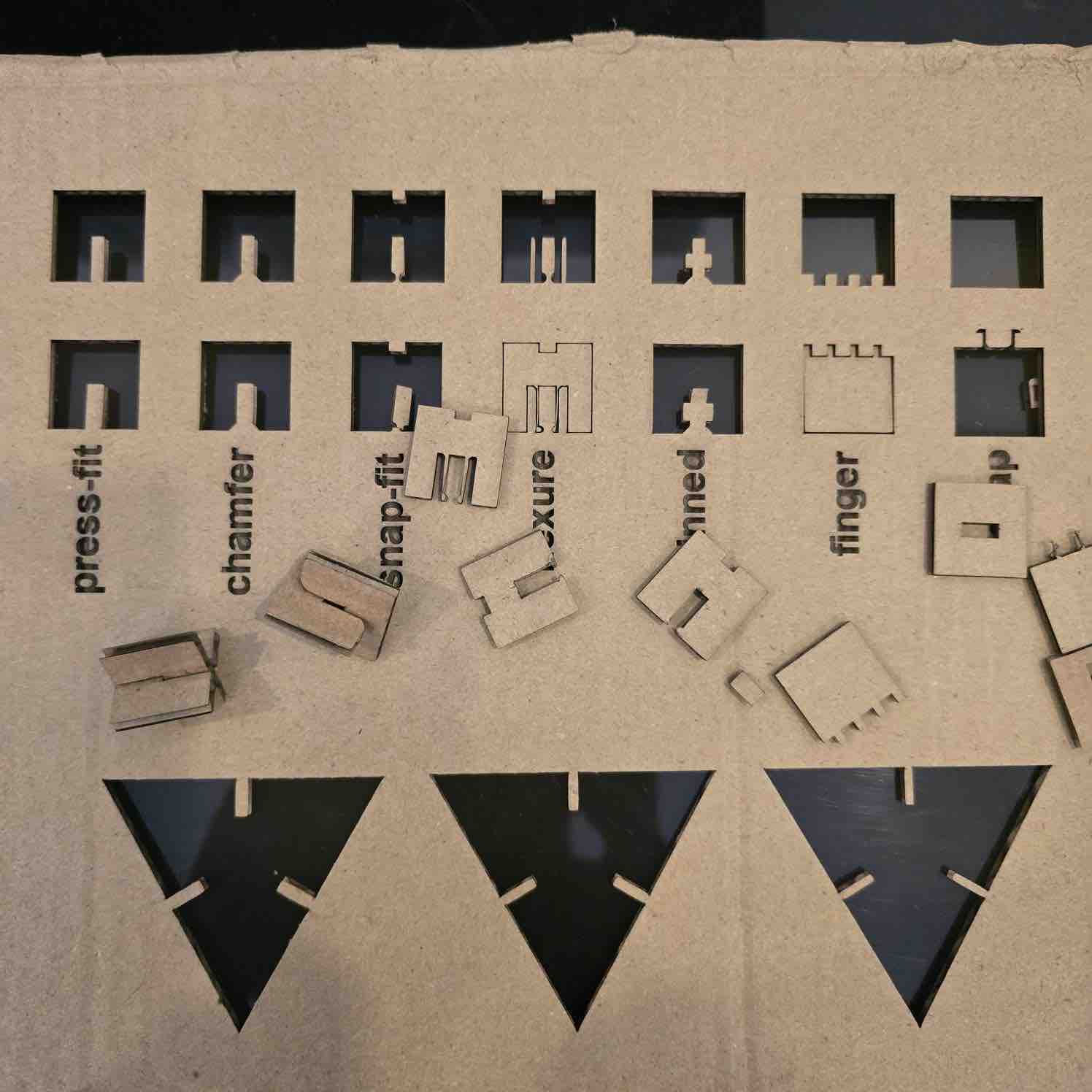
| What did you design? | 
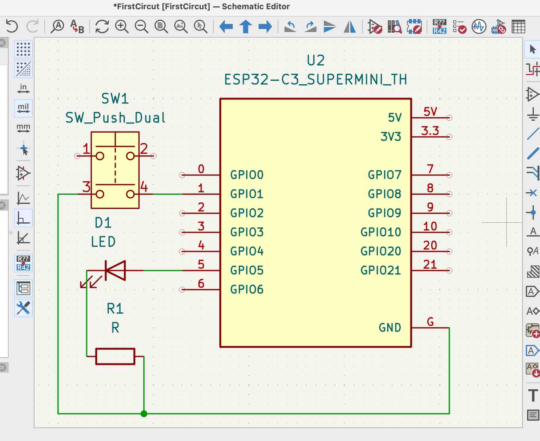
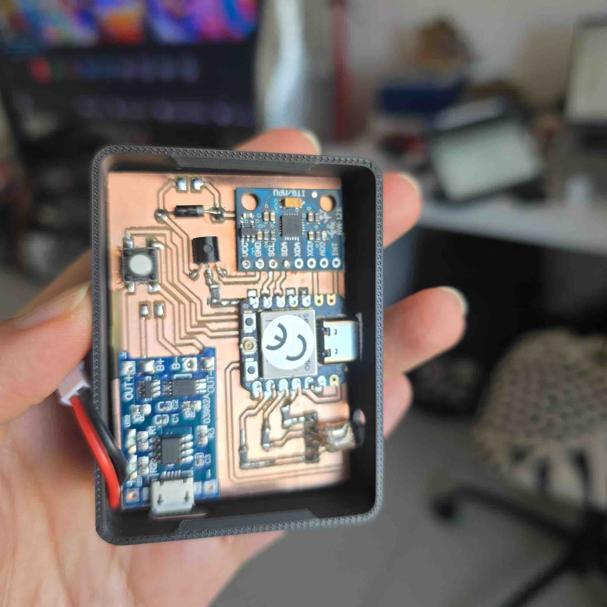
I designed a lot for this! I created the custom PCB for the shoulder clips in KiCad, the 3D-printed housings that snap onto clothes, the layout for the charging case, and the entire mobile app interface. I started with a complex vest idea but simplified it into these modular clips. |
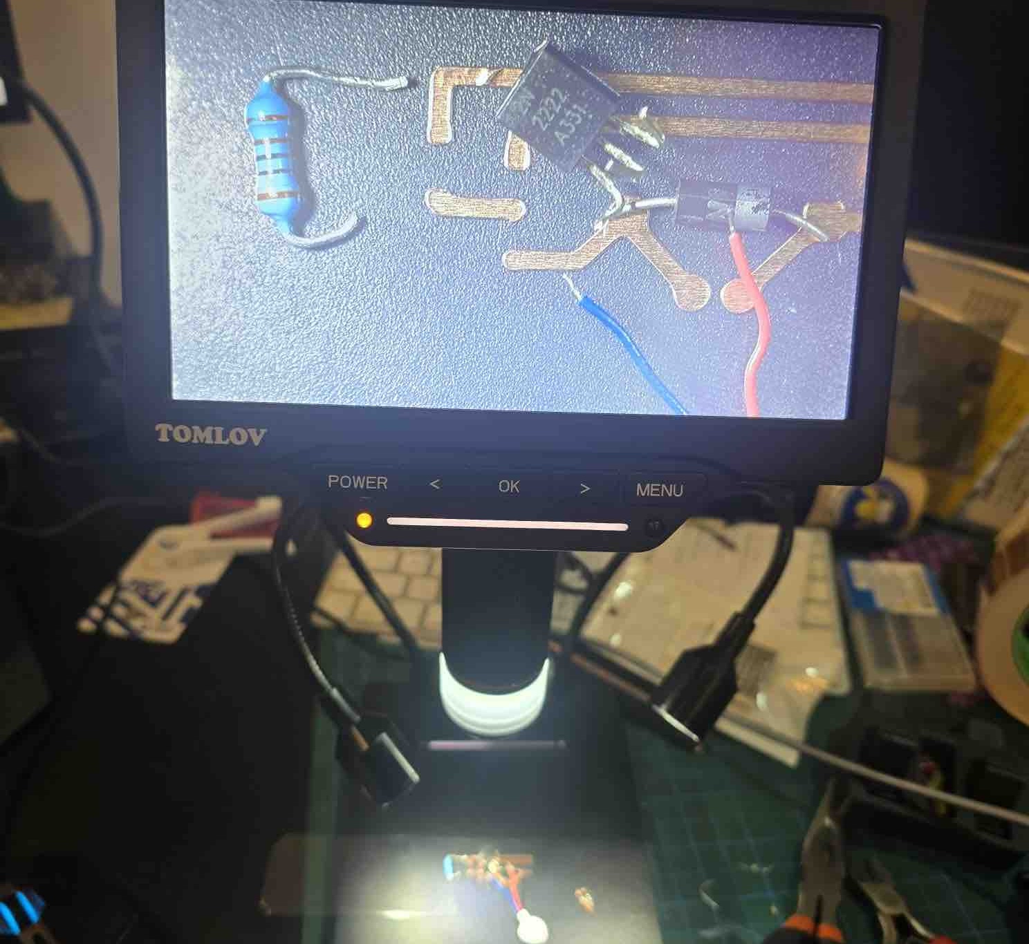
| What materials and components were used? | 
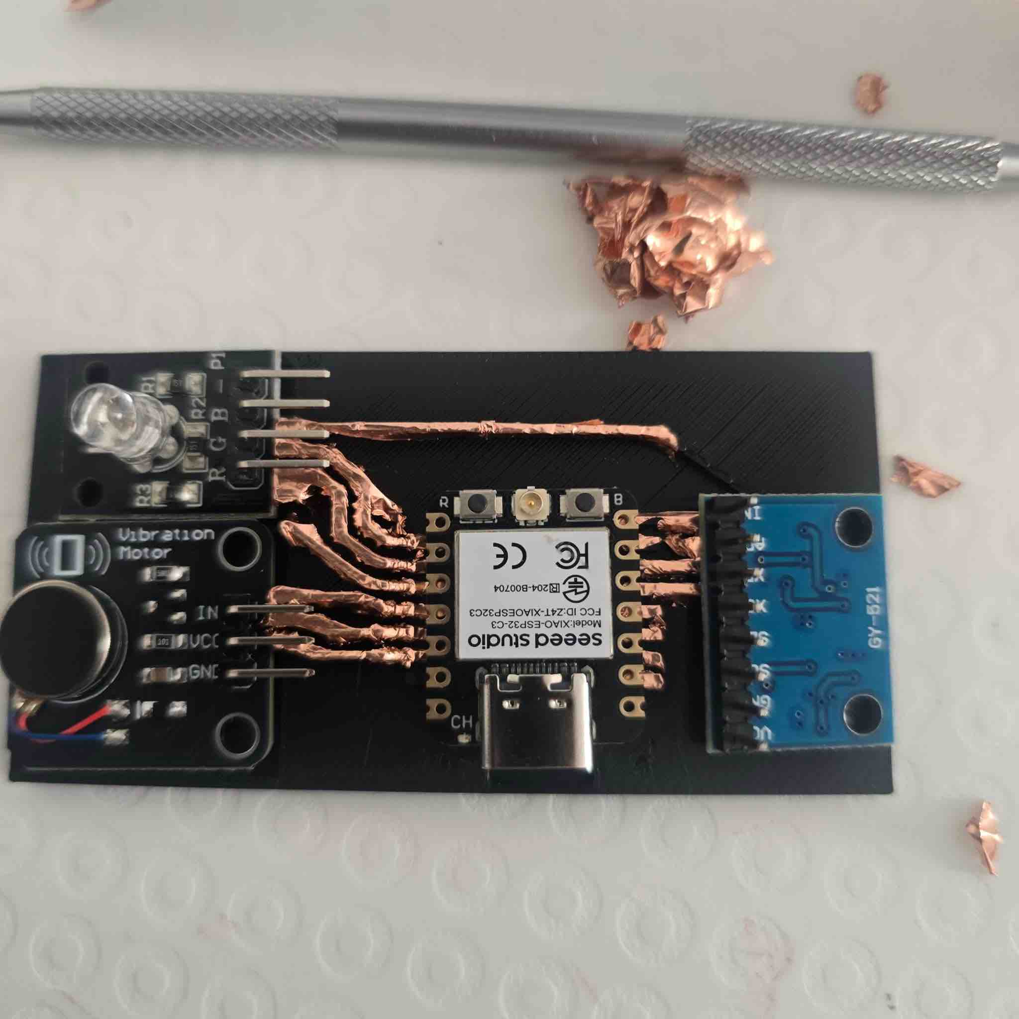
The main parts are 2x ESP32-C3 SuperMini controllers, 2x MPU6050 IMUs, 2x disc vibration motors, and LiPo batteries. For the casing, I used PLA filament, and for the charging station, I used laser-cut wood inspired by my DJI Mic case. |
| Where did they come from? | some from Kuwait market , ordered online and s ome form Vujade lab in Saudi |
| How much did they cost? | I have to define this |
| What parts and systems were made? | 
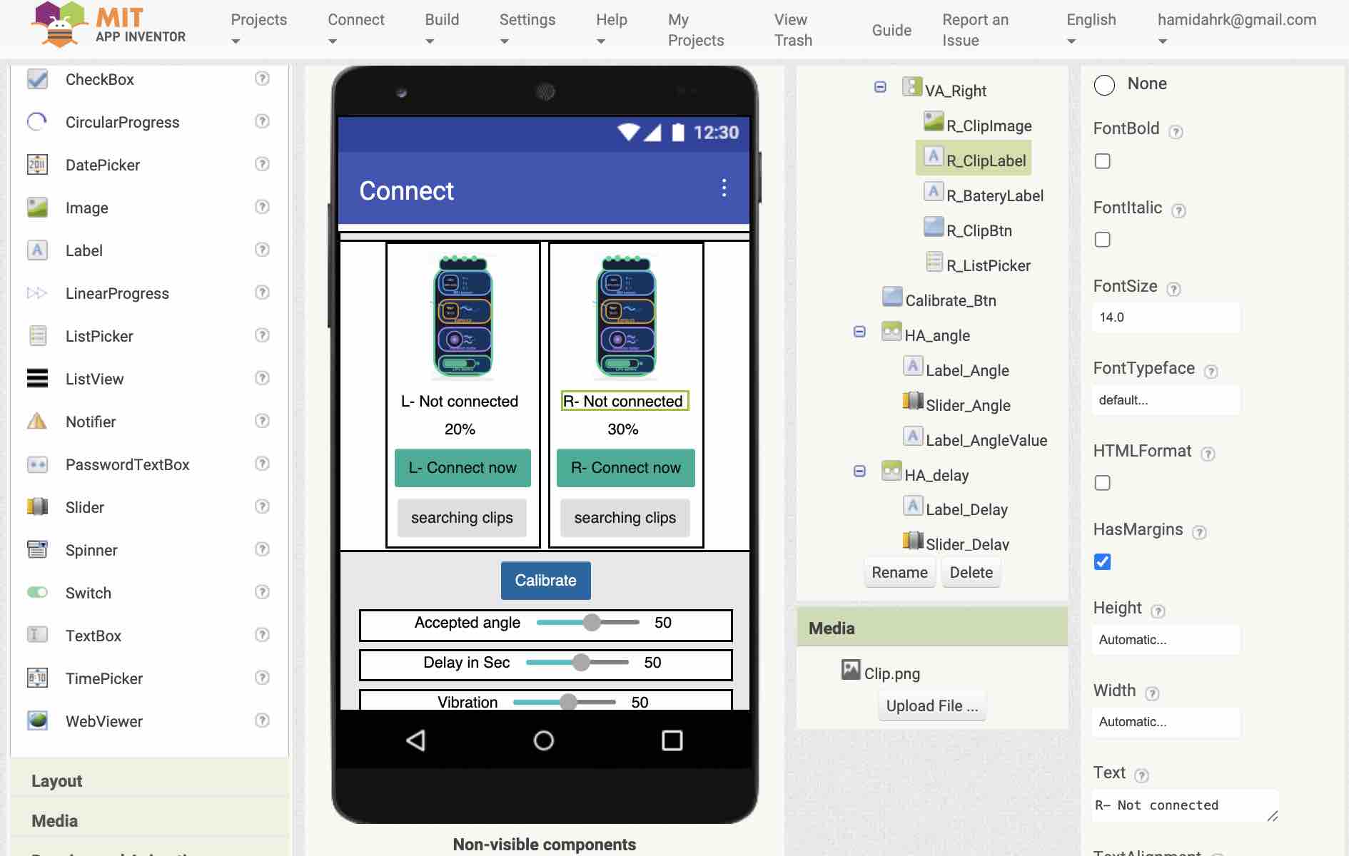
I built three main systems: the hardware clips (electronics + 3D casing), the communication system (BLE data transfer between clips and phone), and the mobile app (the UI for user control and monitoring). |
| What tools and processes were used? | 
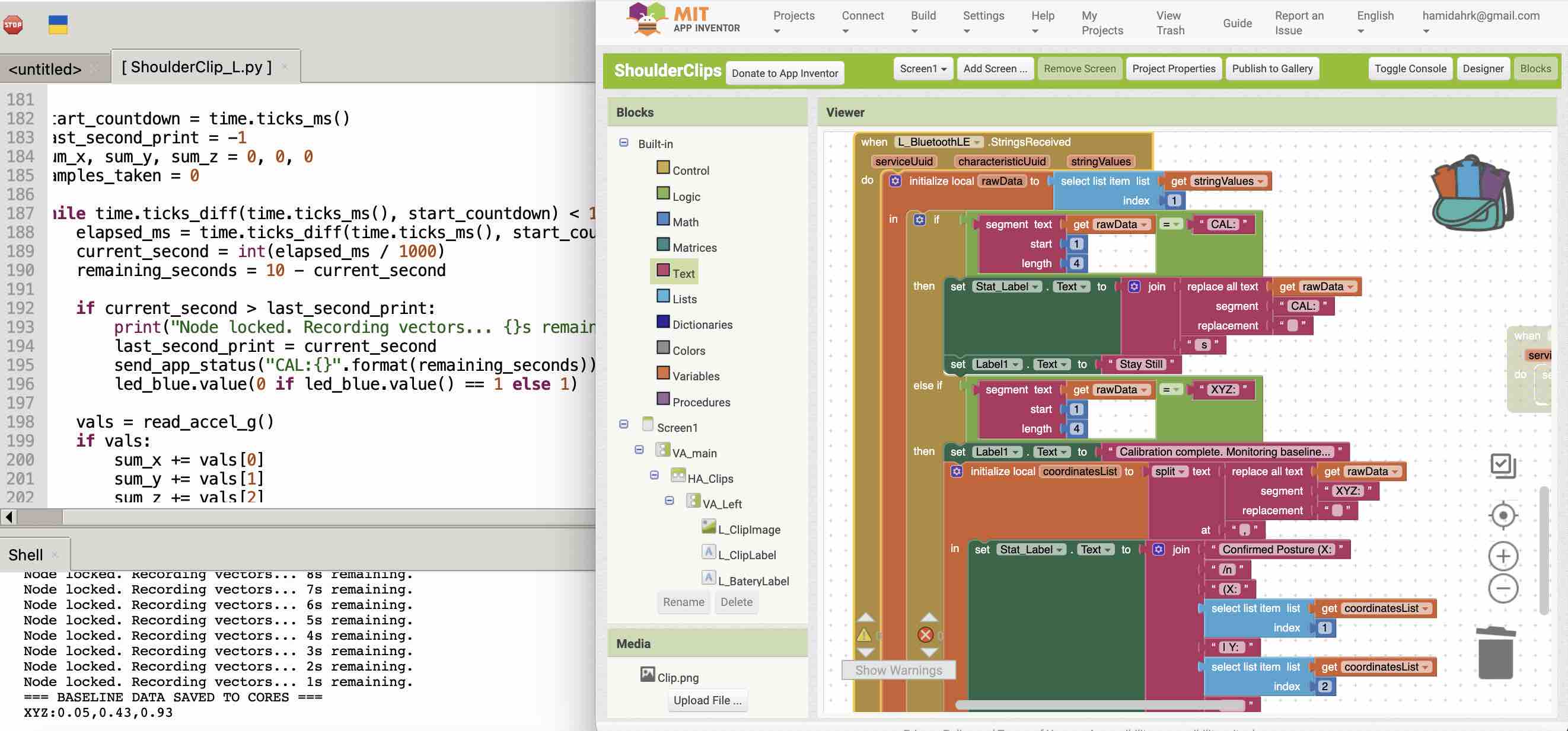
I used KiCad for PCB design, a Roland milling machine for the boards, FDM 3D printing for the clips, and laser cutting for the charging case. For coding, I used MicroPython in a web-based IDE and MIT App Inventor. |
| What questions were answered? | 
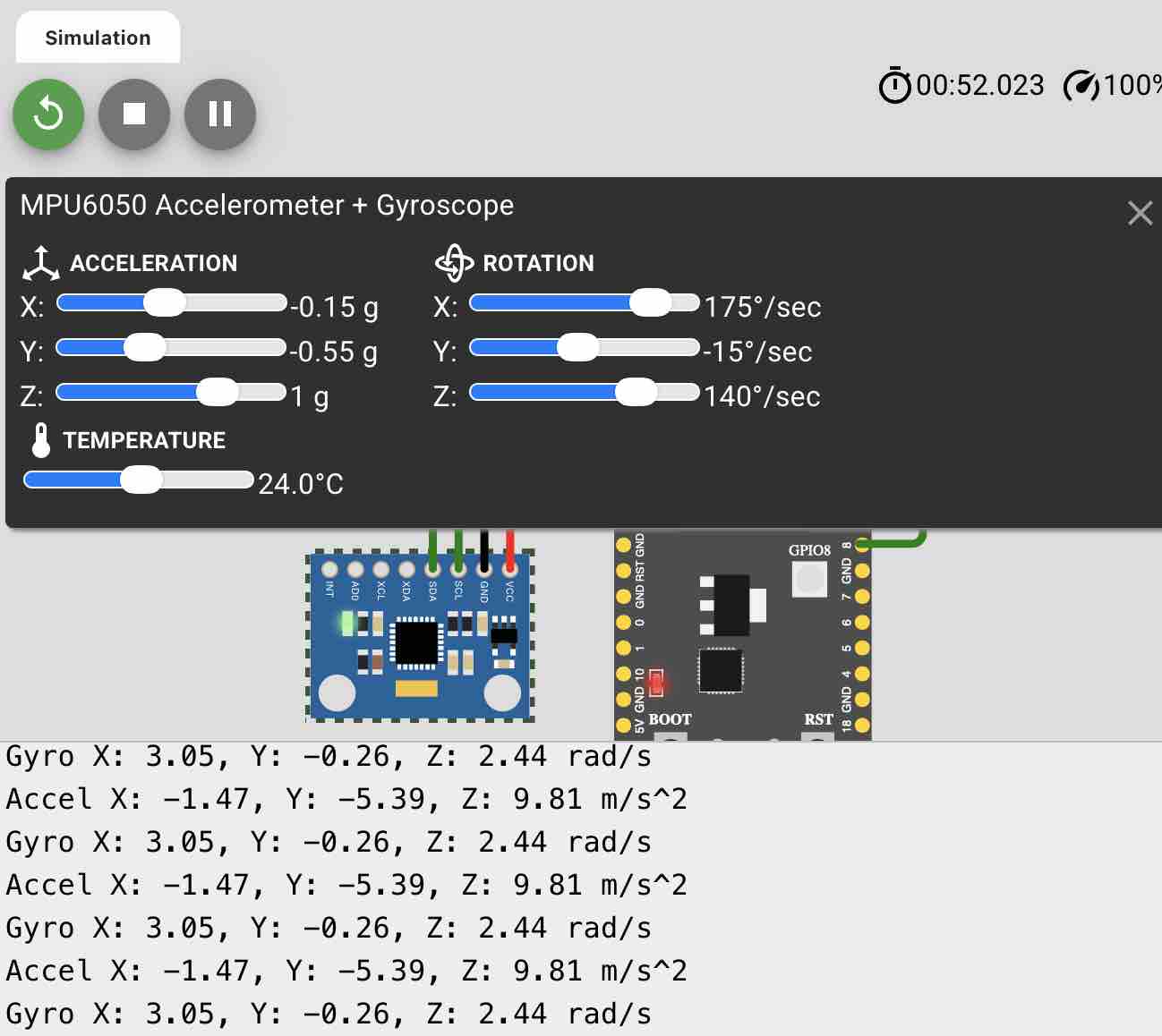
Can two separate sensors communicate reliably with one app? Yes. Can we filter out "fake" slouching? Yes, by adding a custom time delay in the code. Is a dual-shoulder setup better than a single spine sensor? For me, it provides much better feedback on shoulder rounding. Can the case charege the clips wirelessly. |
| What worked? What didn't? | Worked: The BLE connection and the real-time angle tracking are very smooth. Didn't work: My first idea for a wearable vest was too complicated with all the hidden wiring, so I had to pivot to the wireless "clip" design which is much more practical. |
| How was it evaluated? | still in the process |
| What are the implications? | This shows that we can make personalized health tech that isn't just a generic "one size fits all." My background in yoga and anatomy helped me design something that actually feels natural, and the tech can be adapted for other types of physical therapy. |
All design files, source code, and references for the project. Replace each # link below with the real file URL (GitLab raw link, repo path, or local file) once uploaded.
| Subsystem | File | Format | Tool | Download |
|---|---|---|---|---|
| Shoulder Clips — Electronics | ||||
| PCB schematic | shoulder-clip-schematic | .kicad_sch | KiCad | download |
| PCB layout | shoulder-clip-pcb | .kicad_pcb | KiCad | download |
| PCB cut file | shoulder-clip-pcb | .svg | Illustrator / cutter | download |
| Firmware | shoulder-clip-firmware | .ino / .cpp | Arduino IDE (ESP32-C3) | download |
| Shoulder Clips — Mechanical | ||||
| Clip case (top + bottom) | shoulder-clip-case | .f3d / .step | Fusion / FreeCAD | download |
| Clip case print | shoulder-clip-case | .stl | Bambu Studio | download |
| Charging Case | ||||
| Case body design | charging-case | .f3d / .step | Fusion / FreeCAD | download |
| Laser-cut layout | charging-case-laser | .svg / .dxf | Illustrator / xTool | download |
| Wireless-charging board | charging-case-pcb | .kicad_pcb / .svg | KiCad | download |
| Mobile App | ||||
| App project | posture-app | .aia | MIT App Inventor | download |
| App build | posture-app | .apk | MIT App Inventor | download |
| Project | ||||
| Bill of materials | bom | .xlsx / .csv | Excel / Sheets | download |
| Final video | final-project | .mp4 (1080p) | — | download |
| Summary slide | final-project-slide | .png (1920×1080) | — | download |
| Source repository | gitlab.fabcloud.org/…/hamidah-rahimi | Git | GitLab | open repo |
License: unless noted otherwise, all original files are released under CC BY-NC 4.0.