The process
Group assignment
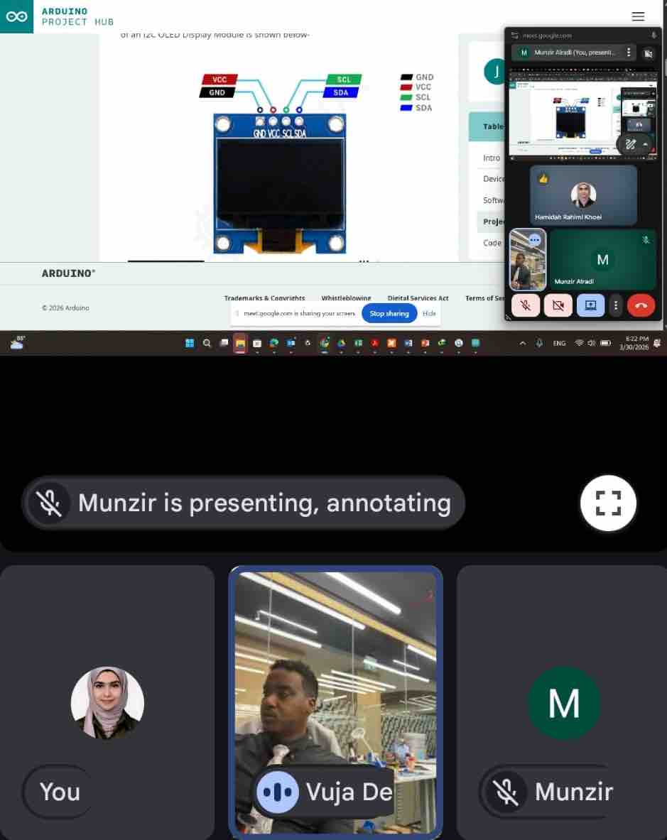
01| Group assignment was conducted at Vujade Lab in Riyadh and I joined the team online
02| My colleague Sarah AlDosary has documented the full process in detail; I will cover some highlights on my page.
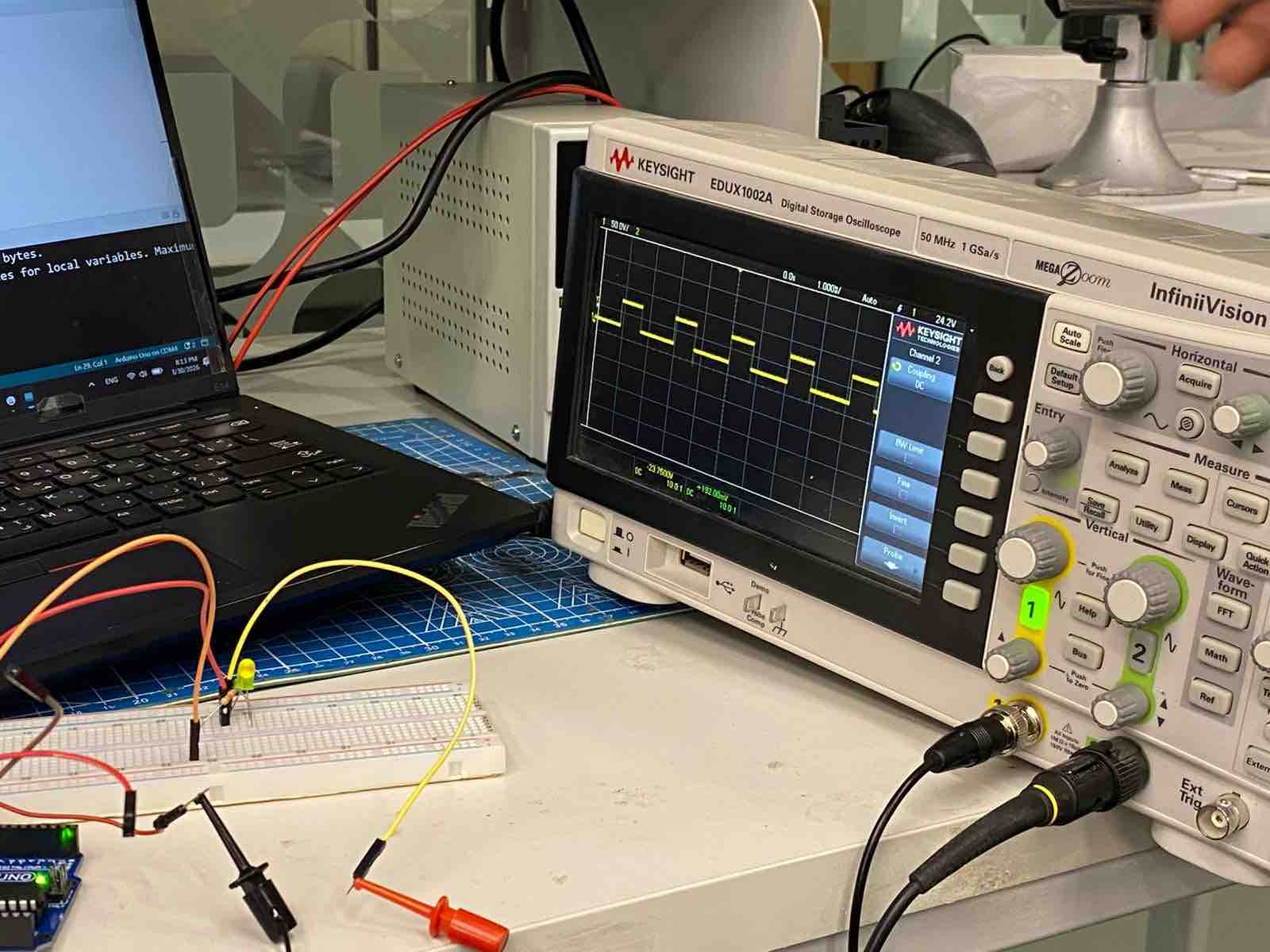
- Feedback: Even though I don't much enjoy joining the lab virtually, it's the only option I have in this phase. I've always been controlling digital signals to control outputs — this is the first time learning how it really works.
- Challenge: Getting an oscilloscope for our lab in Kuwait
Individual assignment:
01: Vibration motor Moduler
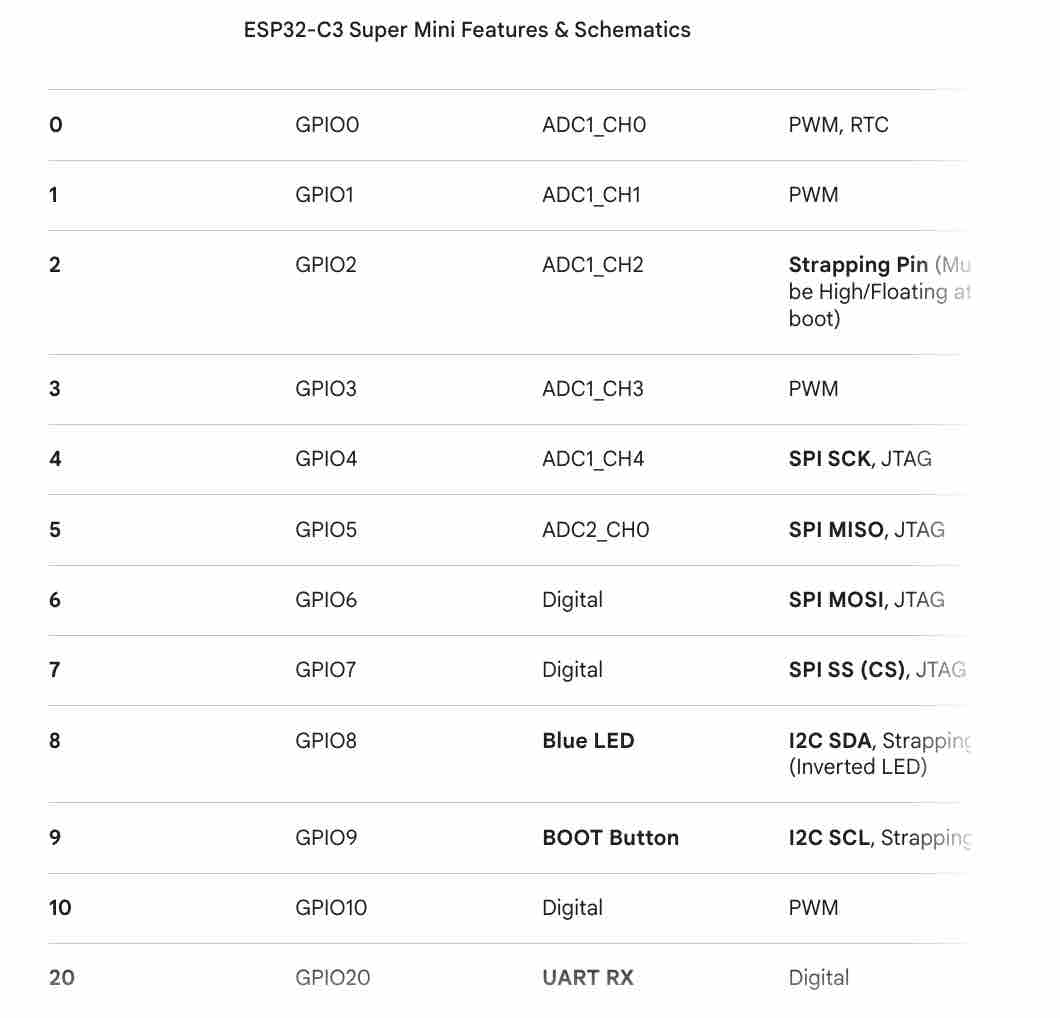
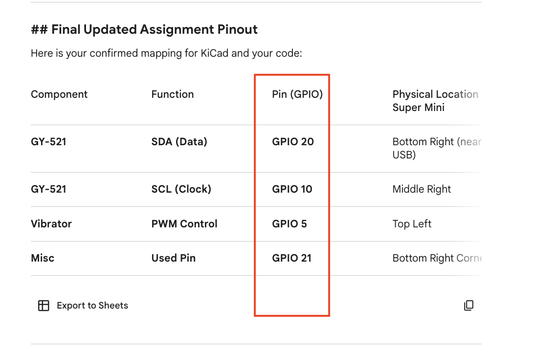
01 | I started this task by making sure I define PWM pins on the ESP32-C3 SuperMini, with the help of AI Gemini
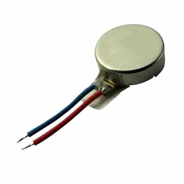
02 | I chose the vibration motor as the output for this assignment, as it will also be used in my final project
03 | With the help of AI Gemini I defined the parts I need to create the driver for the motor and how to connect it to the ESP32-C3 SuperMini
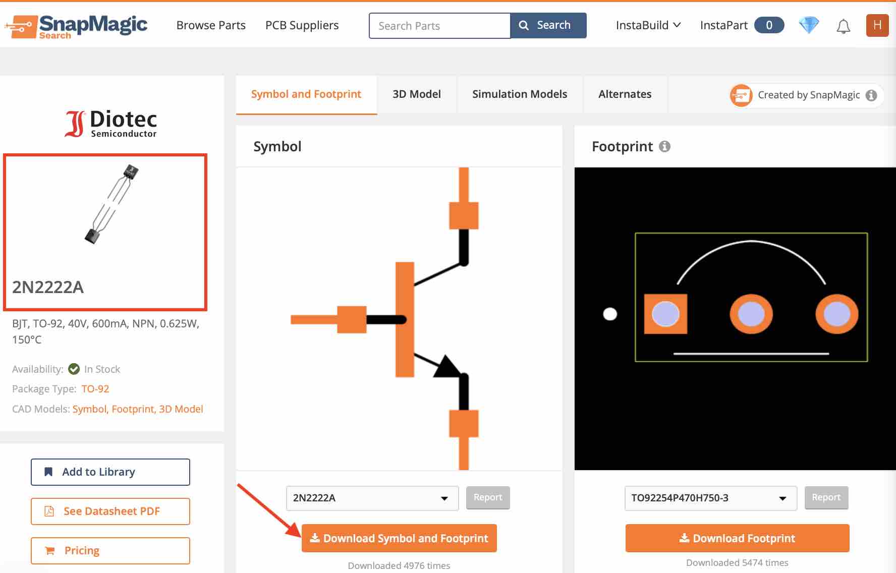
04| I downloaded the symbol and footprint of the Transistor 2N2222
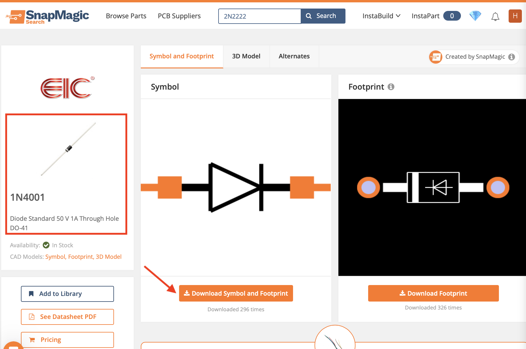
05 | As well as the Diode 1N4001, which will control the current before it leaves the motor
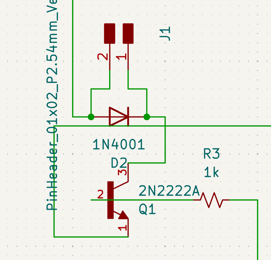
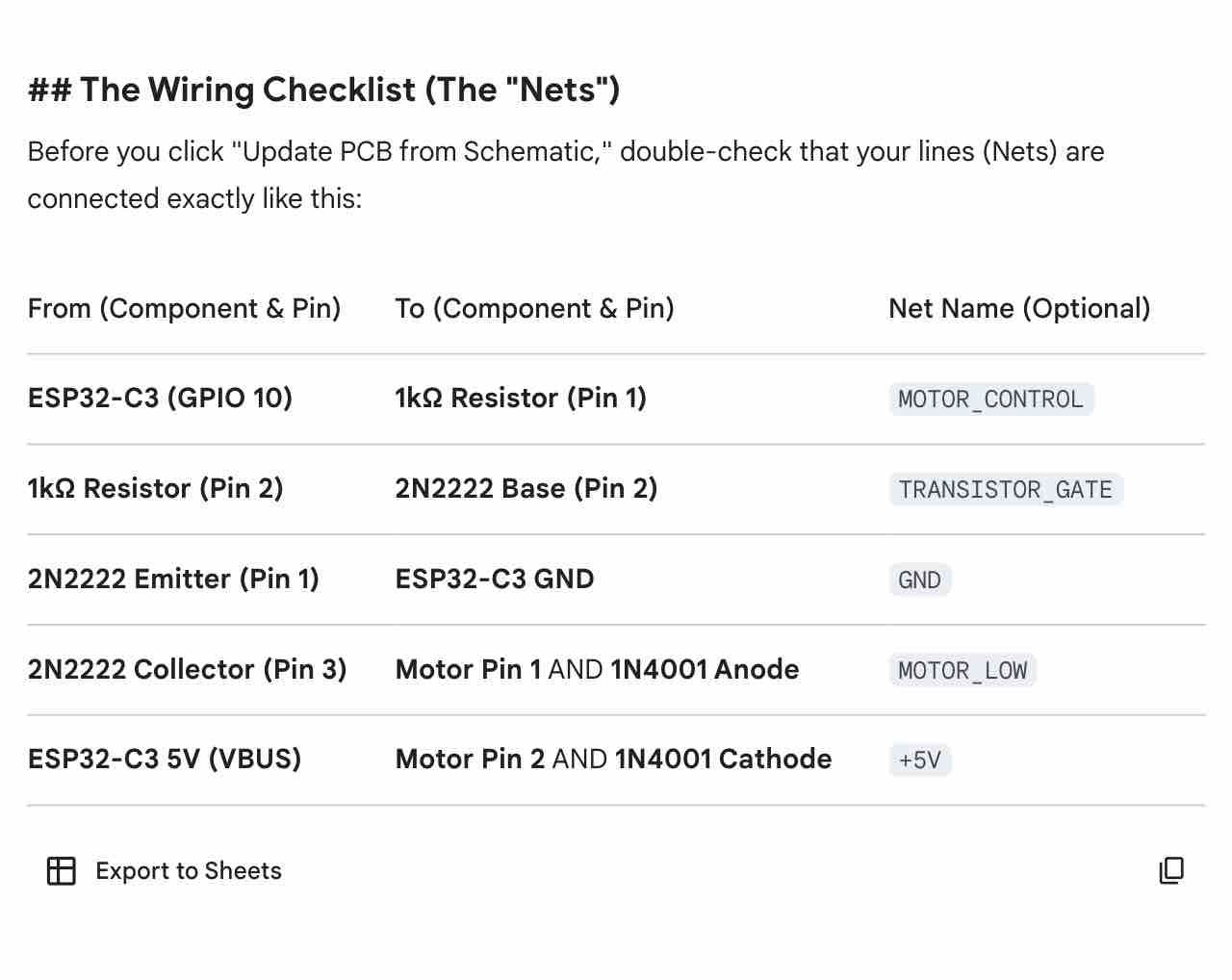
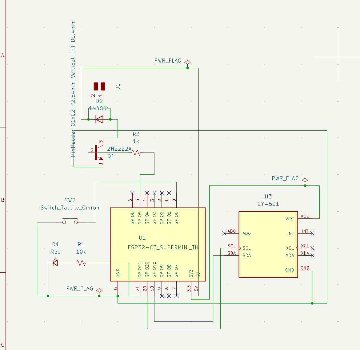
06 | In the KiCAD schematic editor I added the parts (Transistor, Diode, 1K resistor, hairpin) → connected the parts as defined by AI Gemini → then looked for errors in the Design Rules Checker
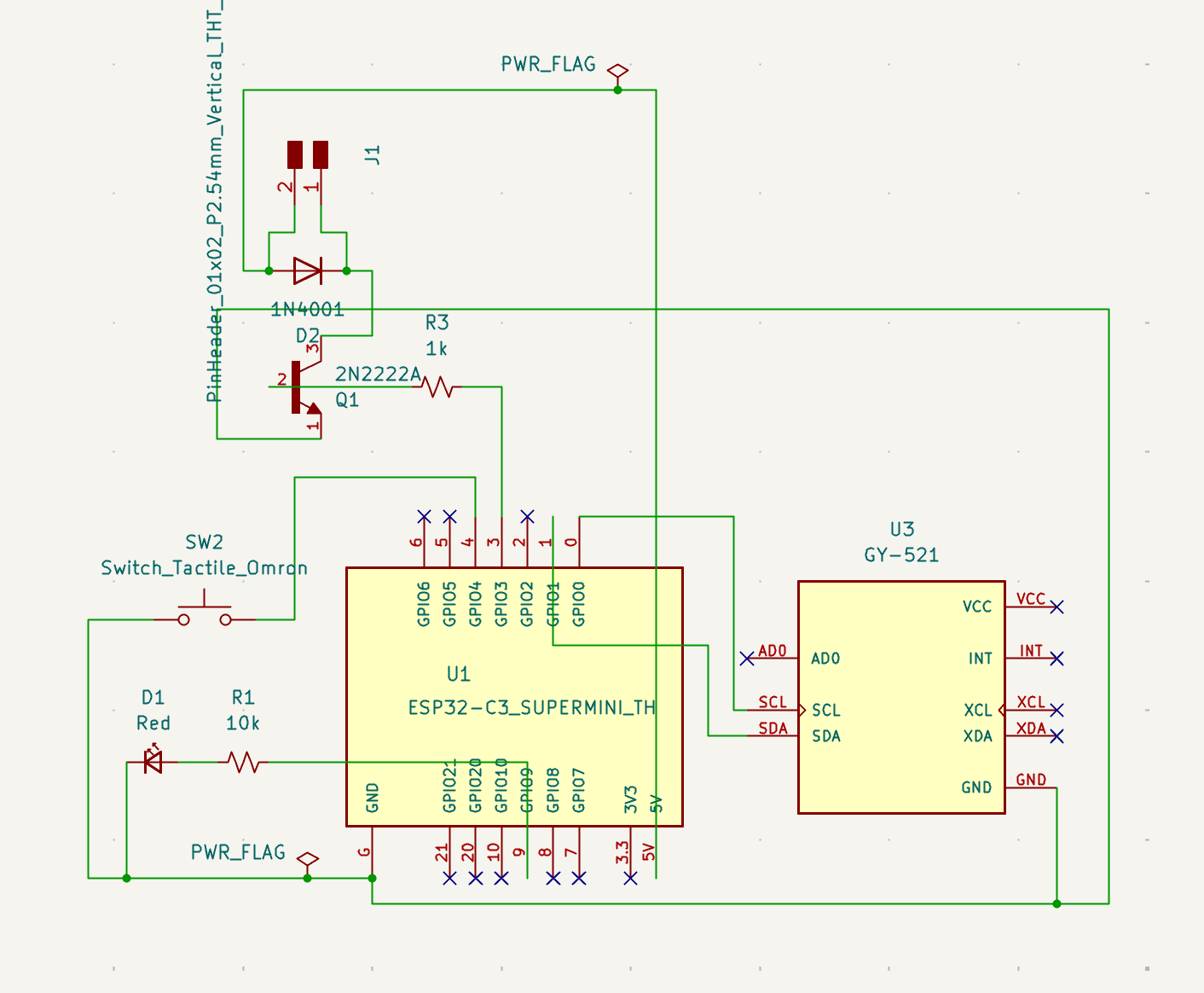
07 | And connected this output driver to the rest of my PCB design
08 | Then I updated the PCB Editor to add the new part
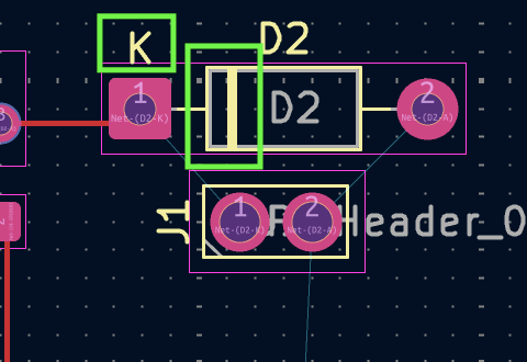
09 | Then I noticed that the Diode cathode was connected the wrong way
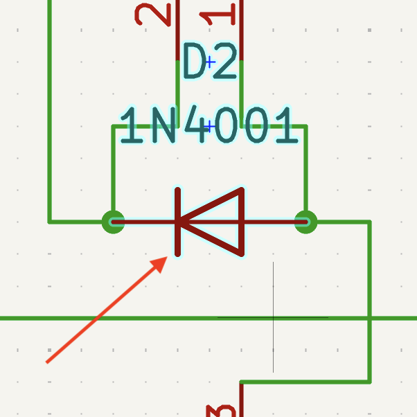
10| I flipped it in the schematic designer first
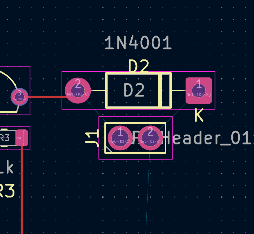
11 | Then I updated the PCB Editor again
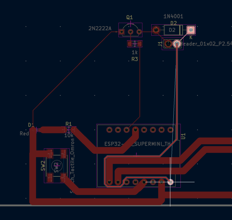
12 | I found that the current layout would not be suitable and I had to rearrange everything
13 | Rechecked the connection with the help of Gemini
14| Rewired all the pins from the input and the output
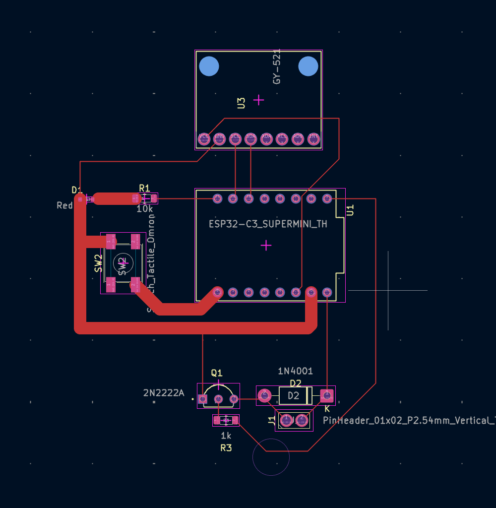
15 | Redesigned the routes on the PCB
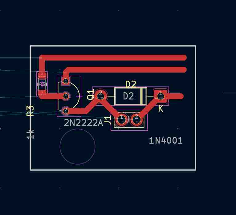
16 | Designed an additional PCB for the vibrator motor driver and made the routes 1mm thick as I wanted to design this driver using the vinyl cutter
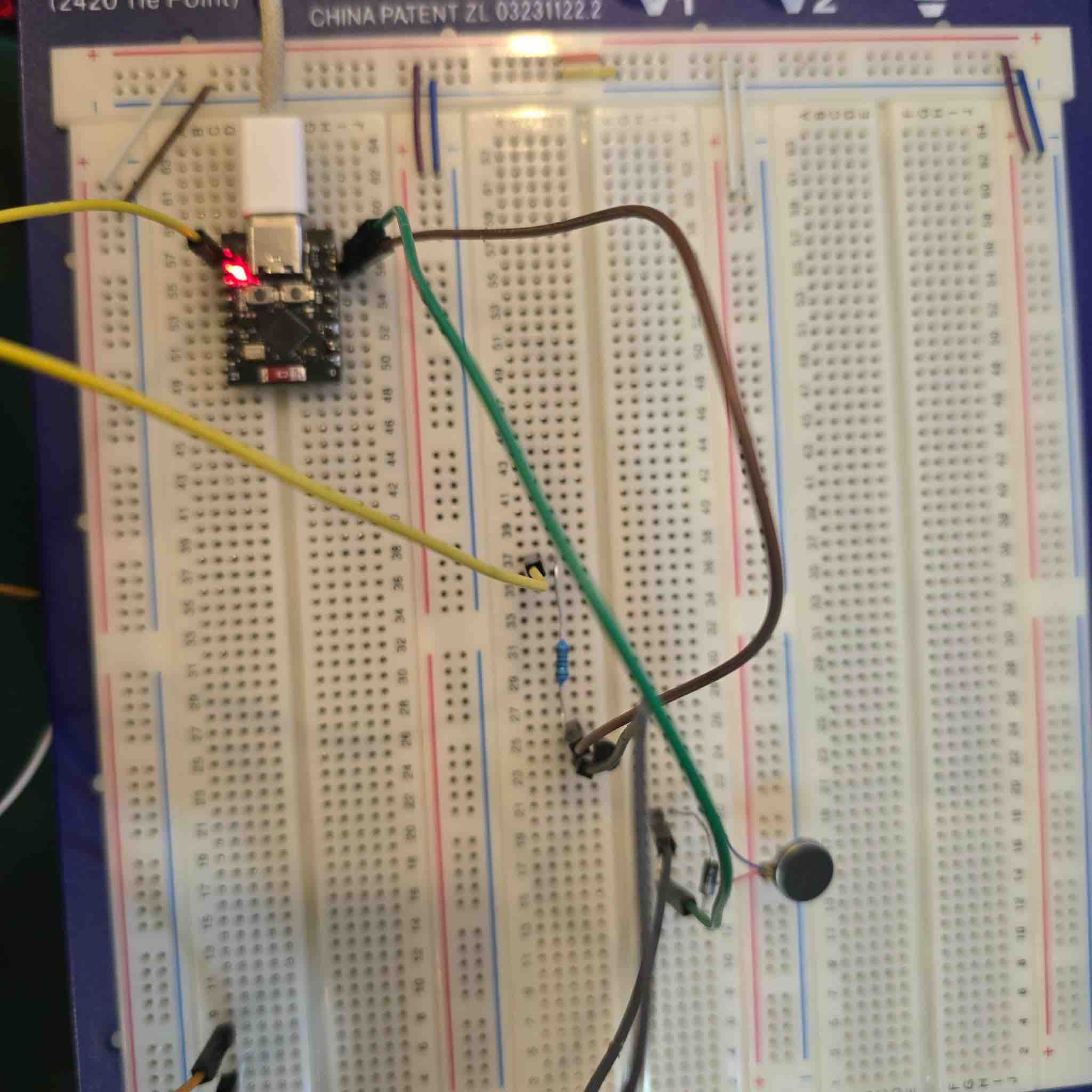
17 | I connected all the parts to the breadboard
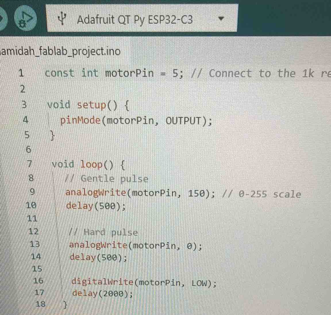
18 | I used generated by Gemini AI to test the vibration power, speed and duration, following this workflow: Open Arduino IDE → select the ESP32 C3 library → copy/paste the code → verify the code → upload to microcontroller → press reset button if needed
const int motorPin = 10; // Connect to the 1k resistor -> Transistor Base

void setup() {
  pinMode(motorPin, OUTPUT);
}

void loop() {
  // Gentle pulse
  analogWrite(motorPin, 150); // 0-255 scale
  delay(500);

  // Hard pulse
  analogWrite(motorPin, 255);
  delay(500);

  digitalWrite(motorPin, LOW);
  delay(2000);
}
19 | It was working — I changed the values and saw how the vibration changed
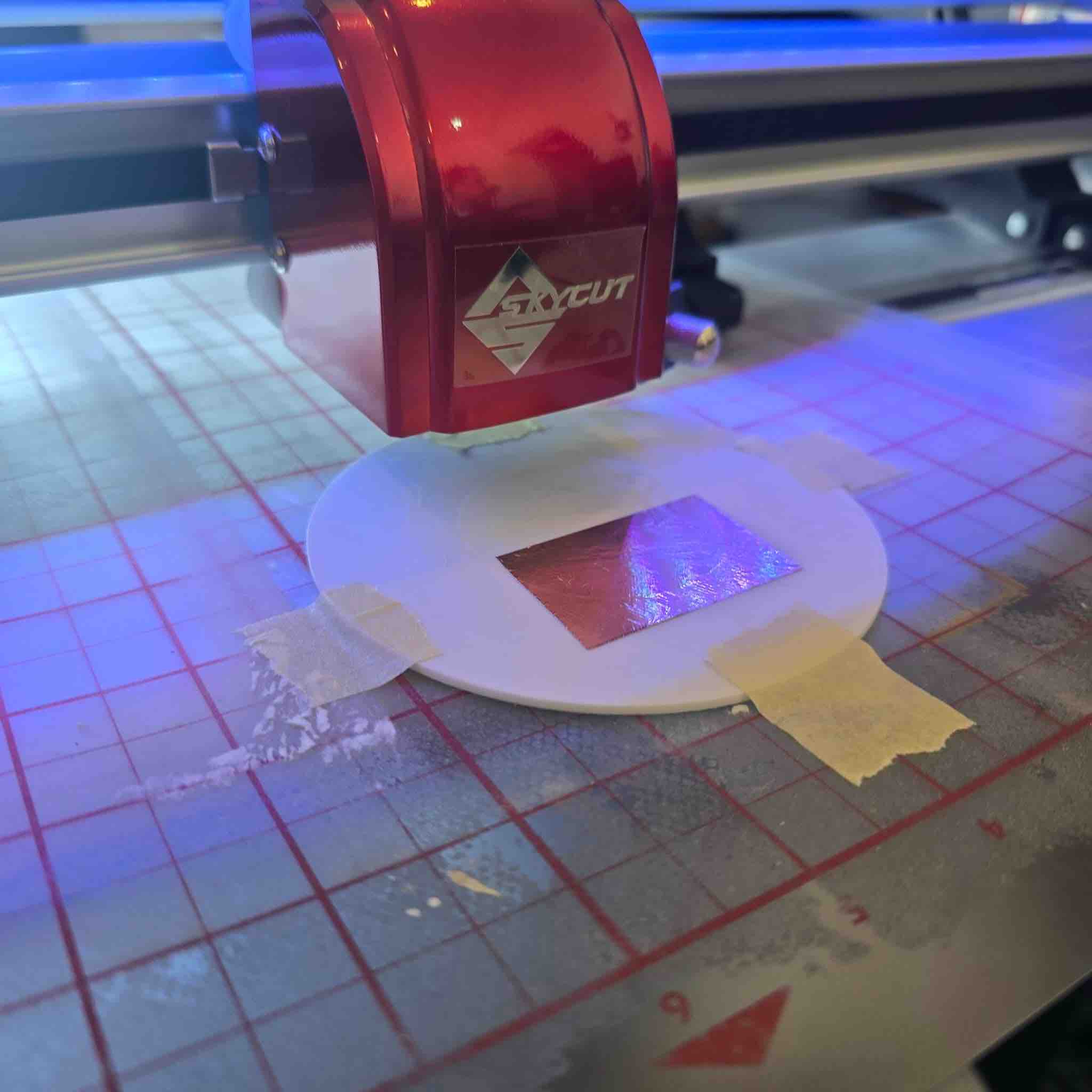
20 | I imported the SVG file of the PCB I designed into SignMaster Pro to use the SkyCutter, and followed this workflow: placed the copper tape on a hard 3D-printed flat plate → taped the plate on the cutting mat → set the cutter to lowest speed and lowest force
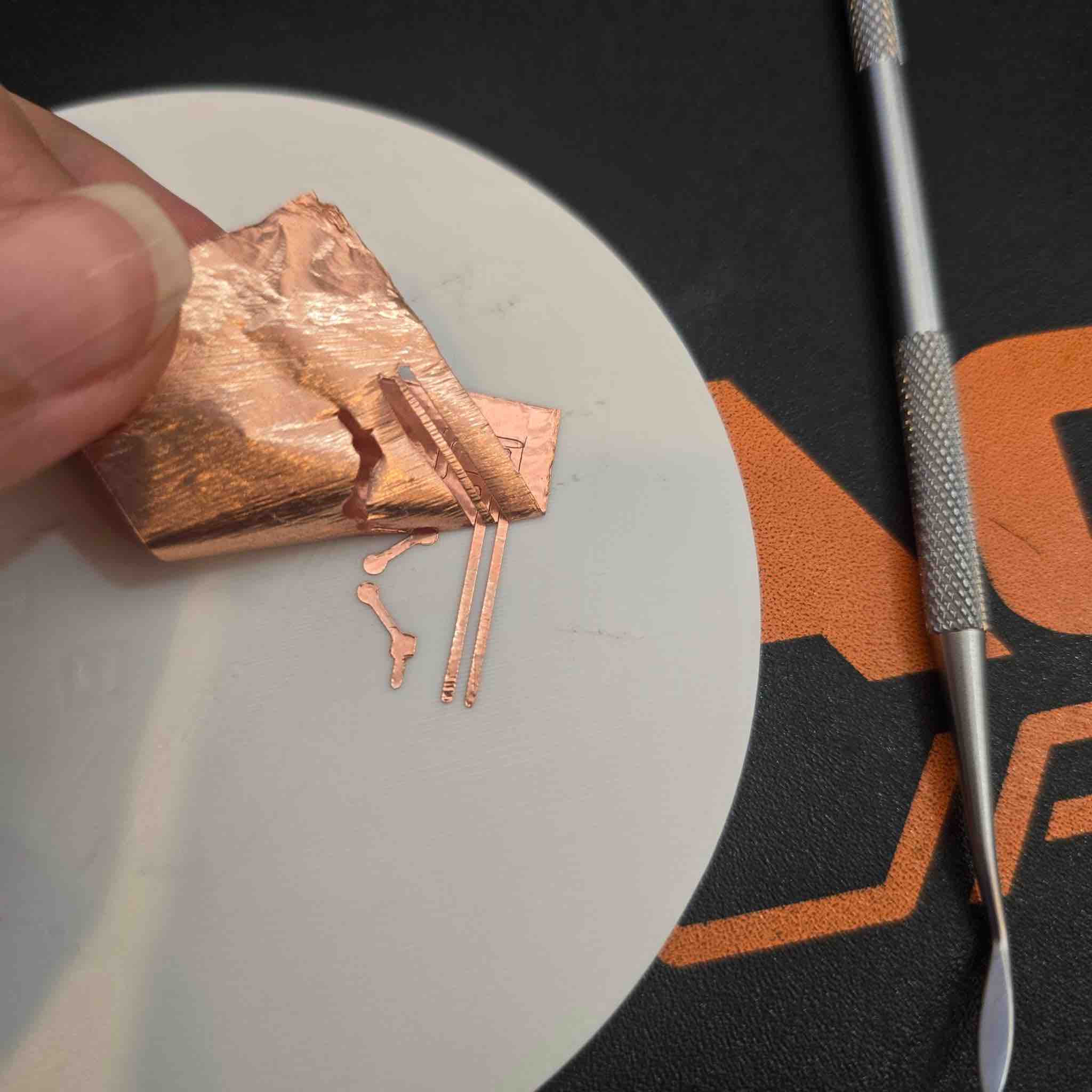
21 | Once it was completed, I removed the unwanted parts and was left with the circuit ready for soldering the parts to it
23 | Then I started the soldering workflow: the solder temperature was at 300 degrees Celsius → put some paste on the solder → made two soldering spots on the circuit → then tried to connect the resistor as the first part
24 | But the copper routes came off with the solder :)))))
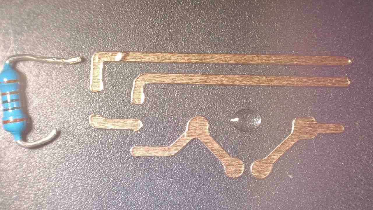
25 | This is my second trial cutting the vinyl circuit
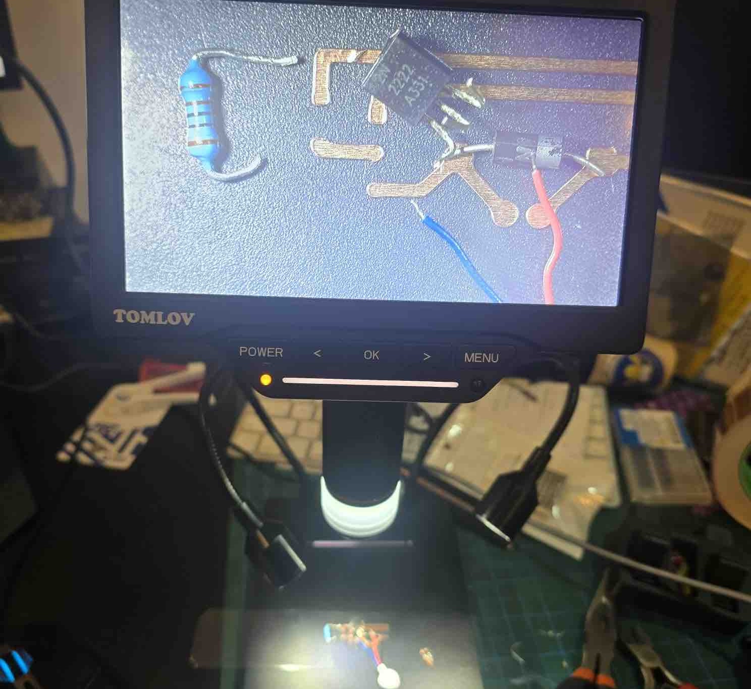
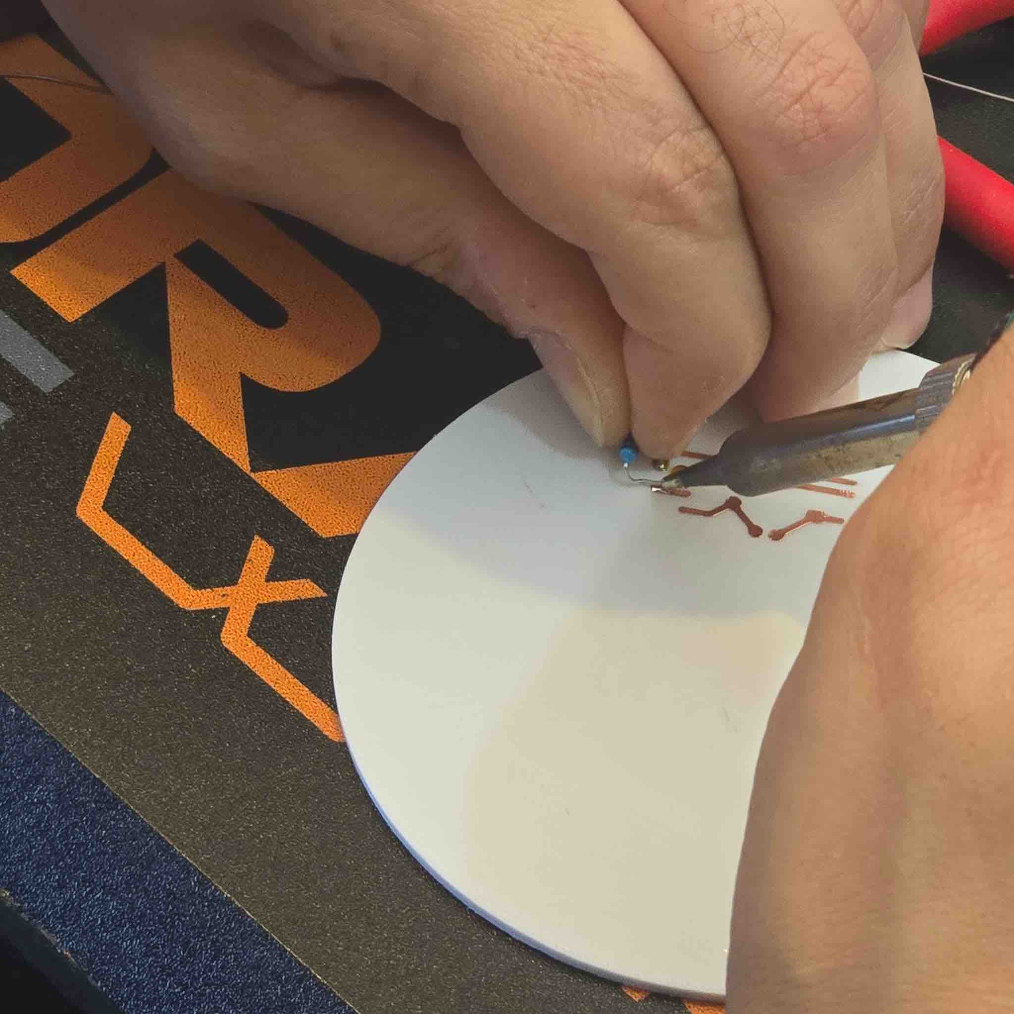
26 | This time I used the microscope to get a better look while soldering the parts
27 | I started by applying small drops of resin that would hold the copper circuit as well as the small electronic parts I wanted to solder
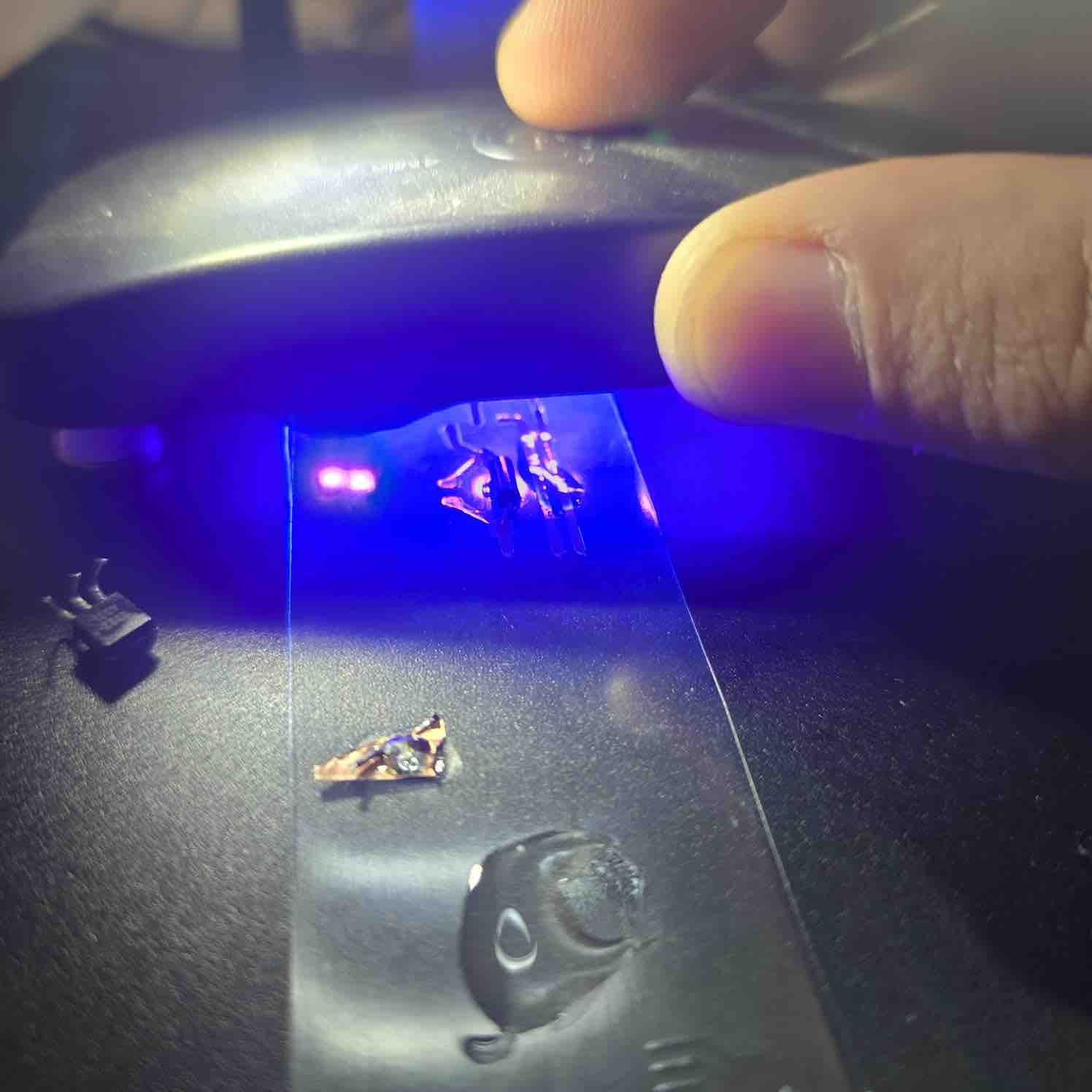
28 | I cured the it with UV blue light before I start soldering
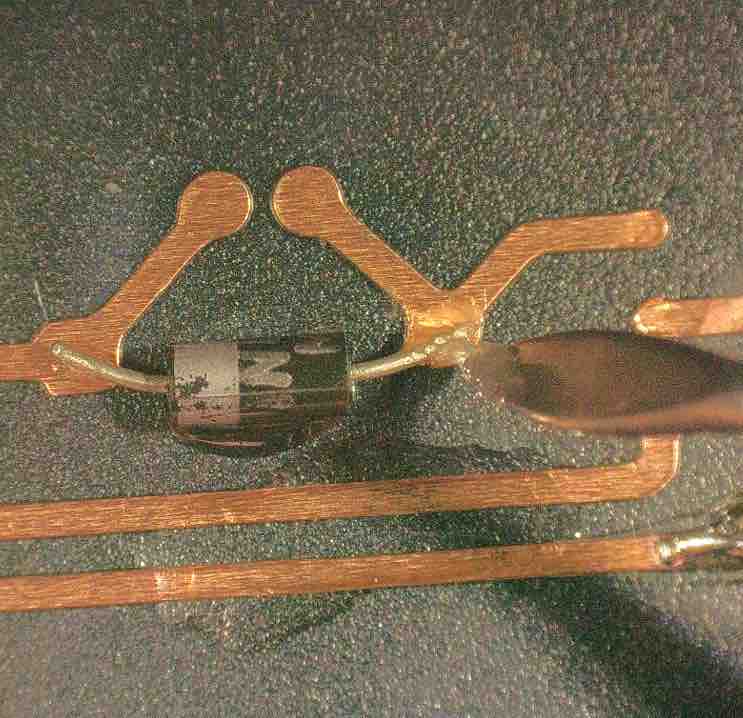
29 | I applied soldering past on the connection parts
30 | I soldered all the parts, but it was not an easy process. I was always afraid of creating short circuits and having to repeat everything. The first parts I soldered were the best (Diode, VM), but as I progressed my soldering got worse, I think for two main reasons: I'm not used to soldering yet, the circuit was very small, and I got both tired and scared of melting the plastic I applied the circuit on.
31 | I used the voltmeter to check for two main things: that I did not mistakenly create short circuits when soldering the parts, and that when using the resin to fix the small parts in place, I did not isolate them from the circuit and solder on top of that. Result: the circuit is complete.
- Feedback: Once I reached this point in the assignment, I remembered what Reco said in the orientation: "You will reach a point in time when you feel you have super powers to create anything you want." And that is how I felt after this assignment. I will still need to print my full circuit with input and output.
- Challenge: I still need more time to learn to use MODS. I saw how it was used in the Global Open Time last Saturday and I'm very interested in learning to use it. Time is always my biggest challenge.
02: RGB LED
Because of the situation in the country and the market, I did not have access to SMD LEDs, so I started disassembling some old parts and modules to reuse the components in my projects. For my final project, I needed an RGB LED to indicate different statuses.
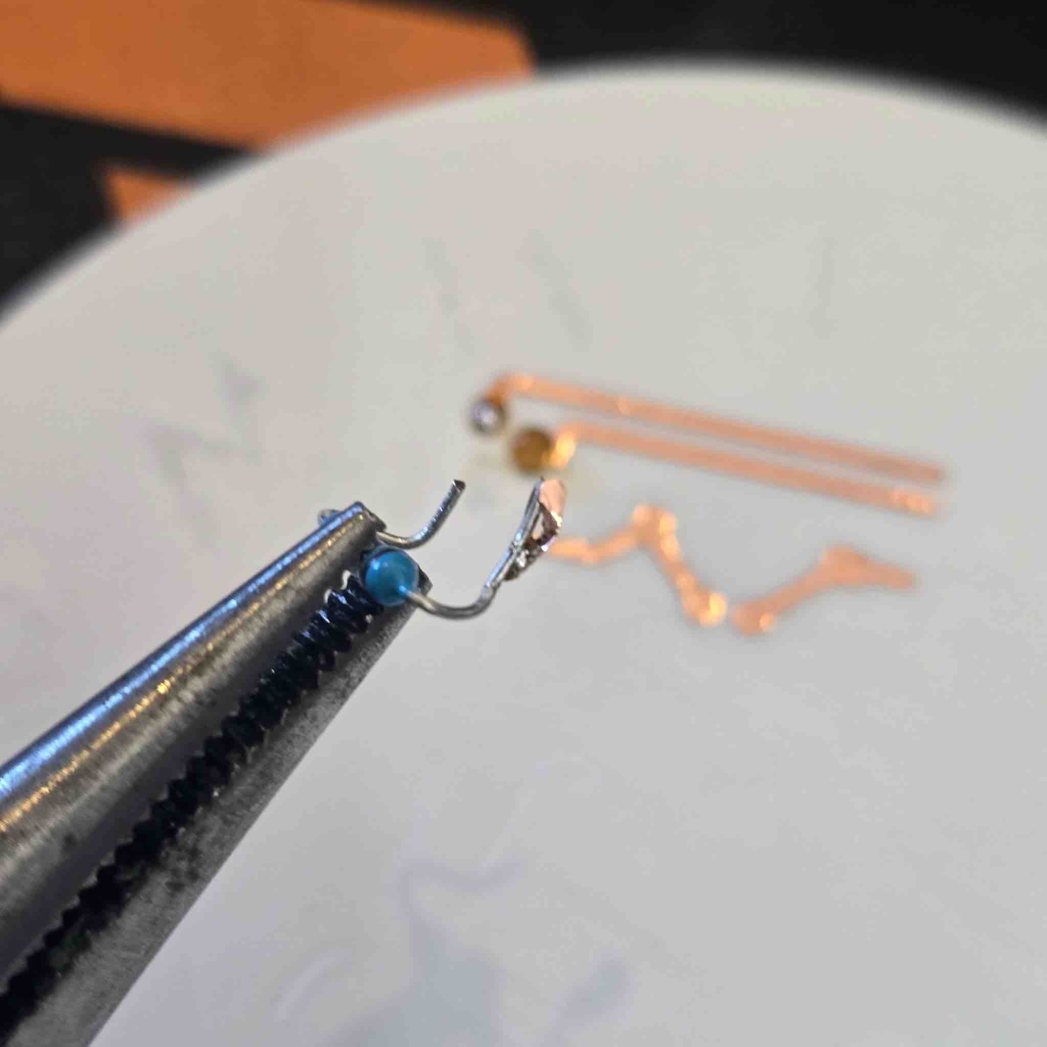
01 | I needed to confirm whether the LED was common cathode or common anode. I used a multimeter for that: first I turned on continuity / diode mode → connected the red probe (positive) of the multimeter to one of the legs → touched the black probe (negative) to each of the other legs in turn → I kept trying different combinations until I could identify the common Anode, Red, Blue, and Green legs.
02 | I bent the legs of the component I needed to use and considered the order of the legs when laying out the schematic for the circuit I was designing.
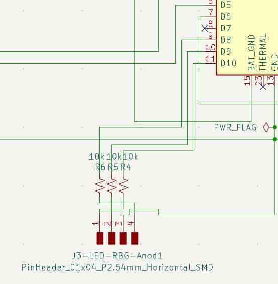
03 | This is the schematic added to my project. I included a 10K resistor for each colour leg connected to a pin on the microcontroller.
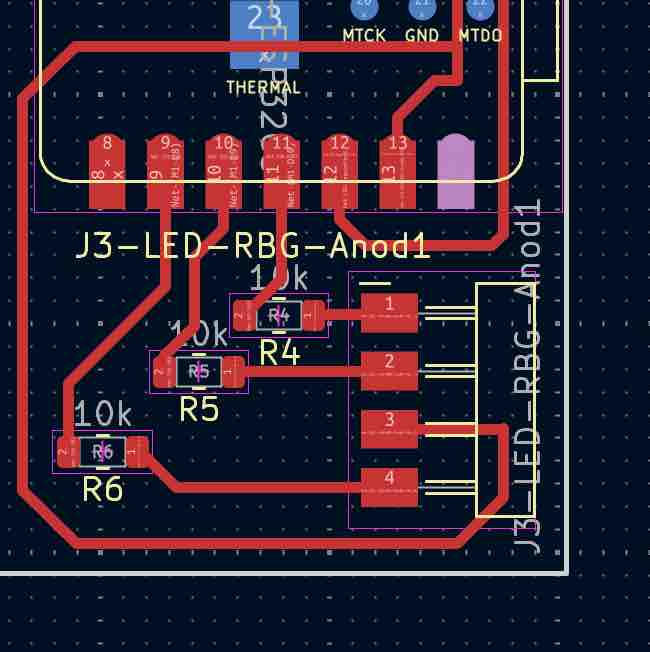
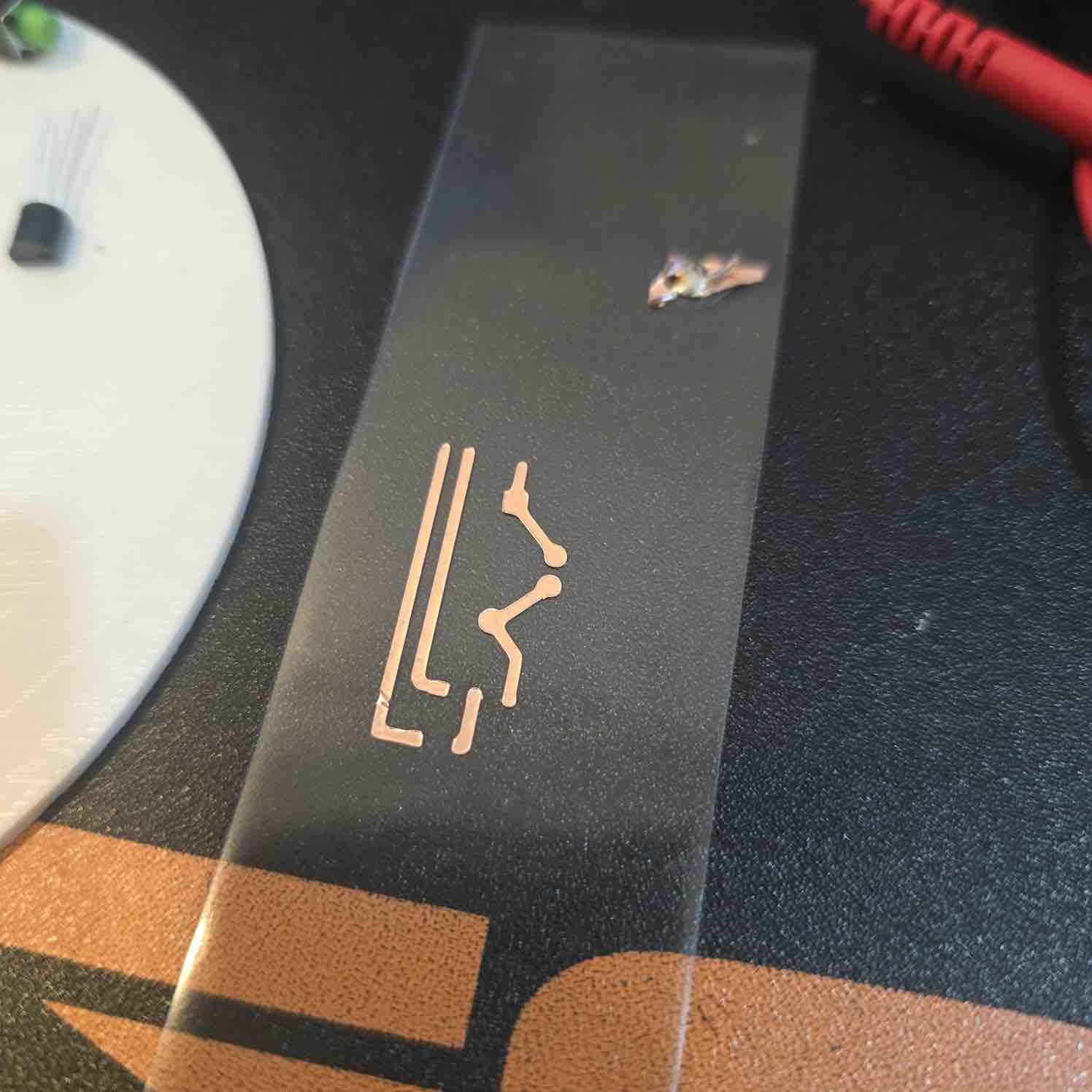
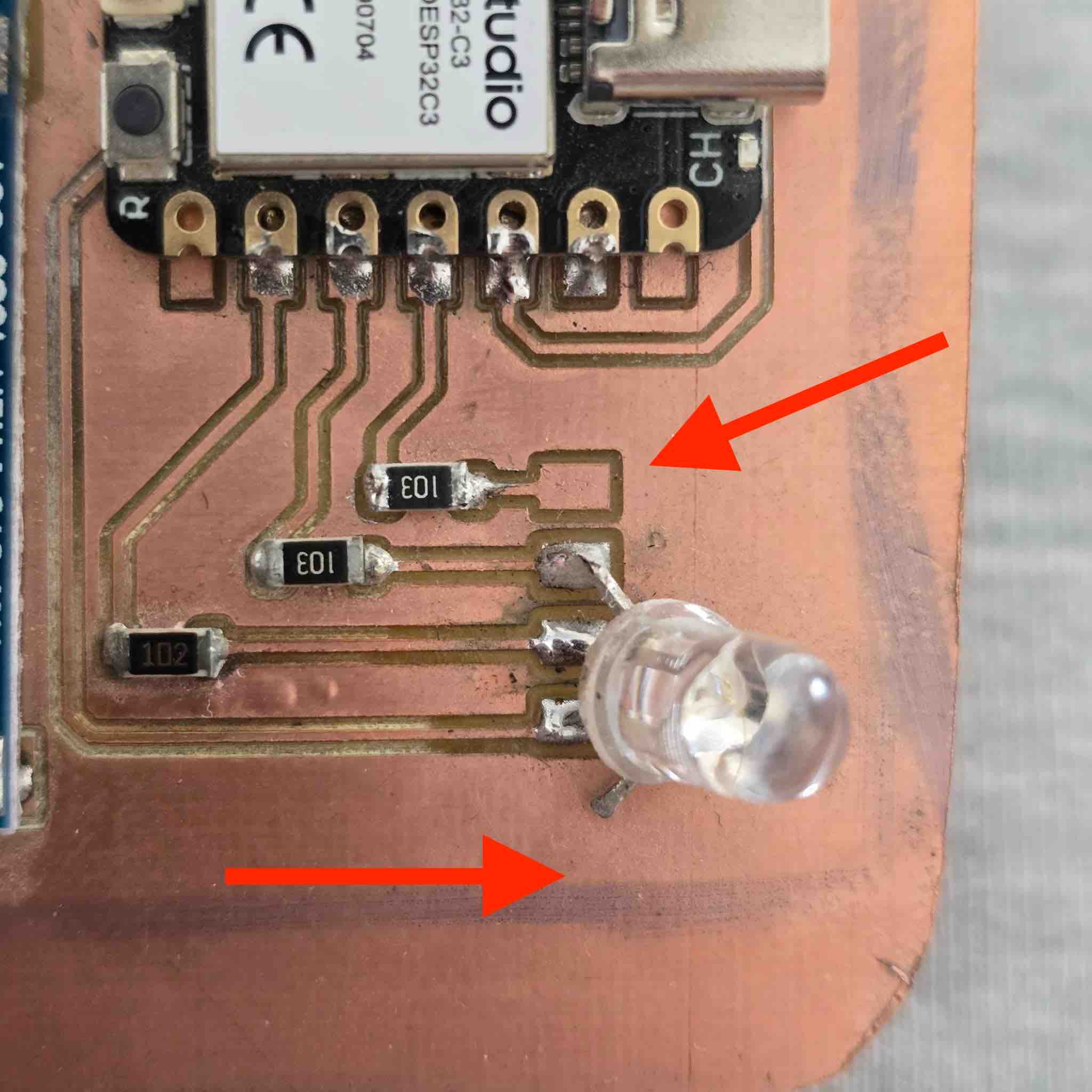
04 | I created the routes based on the actual physical order of the legs. You can see how the 3rd leg has to be routed to ground.
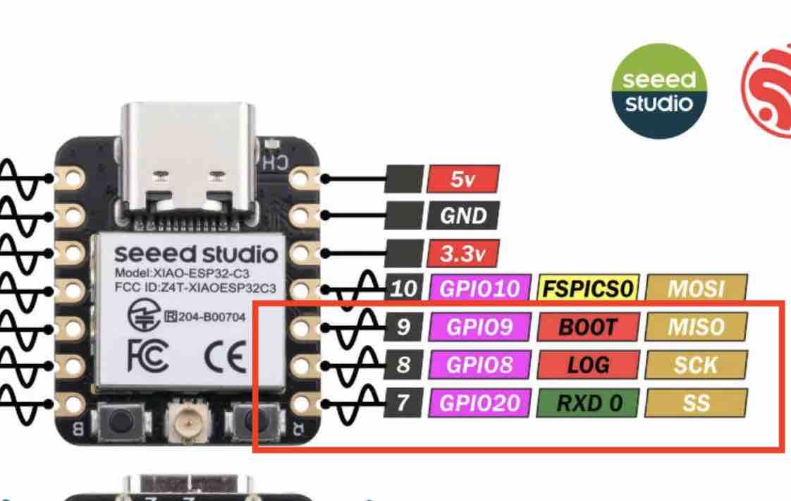
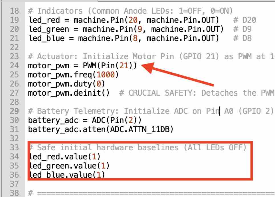
05| The Anode plus GPIO 8, GPIO 9, GPIO 20 — which are Pulse Width Modulation (PWM) pins.
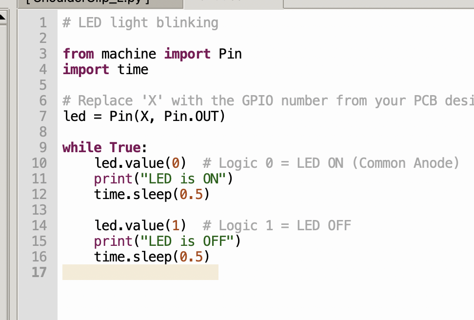
06| One important note for a common-anode LED: in code, sending signal (0) turns the light ON, while sending (1) turns it OFF — the logic is inverted compared to a common-cathode LED.
07| For my final project I used a more advanced code developed with the help of Gemini — for a smoother initialization, to alternate between colors indicating different statuses, and to use blinking for the calibration.
08| In my first attempt at creating the PCB, I misordered the pins, and one of the legs (the red colour) ended up not connected to its allocated pin — so I was only able to use the blue and green colors.
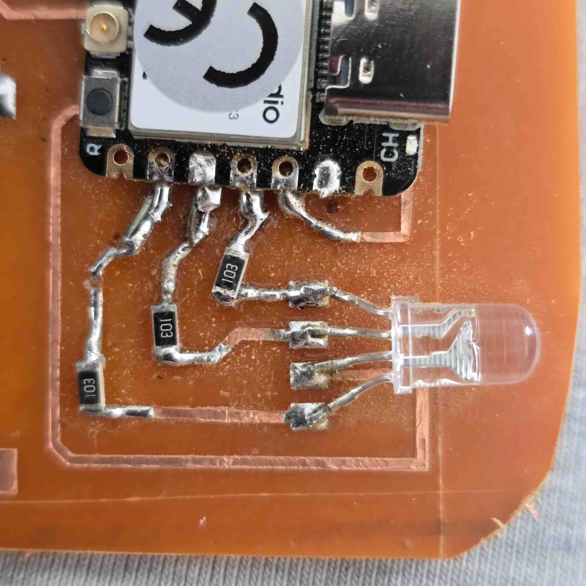
09| In my second attempt with a vinyl-cut PCB, I corrected the routes so all the legs were connected.
- Feedback: I was running out of time and trying to complete the missing assignments while still working on the final project. I was essentially double-documenting — both the assignment details and the final project at the same time. It's important to check the hardware first and make sure I understand the pin positions and the datasheet correctly. The best workflow would be: define the component → read the technical specs and datasheet → bench-test it in the lab to gain practical knowledge → draft a first-version schematic based on that understanding → wire it on the breadboard → update the schematic → design the PCB → mill the PCB or cut on the vinyl cutter → prepare the components → solder → test connectivity for shorts → connect and program.
- Challenge: Most of the time, I worked on the software before going to the lab — so I designed the schematic with the LED legs ordered as R, B, G, Anode, thinking it would be easy to add them on the PCB. After my first trial, the LED didn't work because I had misplaced the Anode. I had to redo the schematic, the PCB design, and the milling. Not having enough materials to keep testing — and not having flexible access to the lab — were the biggest challenges in this learning experience.