My Final Project: PXL
A Spatially - Responsive Immersive NeoPixel Experience
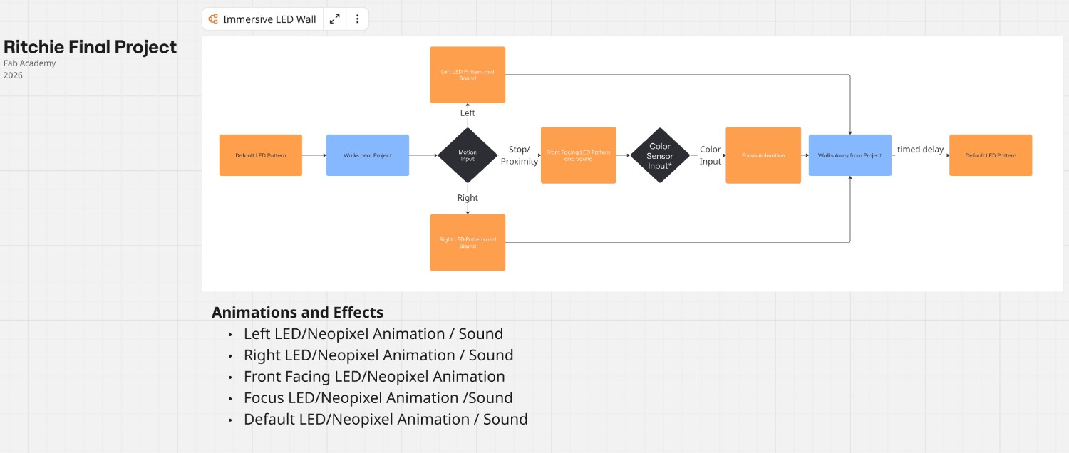
The project I propose building for Fab Academy is a spatially-responsive immersive, interactive NeoPixel experience- PXL. The project tracks users' movements using a TOF sensor and responds through unique patterns of light using a NeoPixel Matrix. The project itself will have mounted to it addressable RGB LEDs as well as a sensor that will track users' movement and distance. The user is an individual curious about this device and who is interested in experiencing a sensory experience. The exhibit is intended to engage, entertain, and create a sense of wonder. The project is designed to grab users’ attention and shape their behavior through responsive light-based interactions. As users walk by the exhibit, approach it, stand in front of it, or walk away, the exhibit responds through animated addressable NeoPixel lighting patterns.

Final Project Slide and Video:
presentation.pngpresentation.mp4
The project is intended to signal to a passersby that it is interactive and to demonstrate how movement maps to visual output.
The animations are designed not only to react to movement, but also to encourage movement. For example, animations that move from the outer perimeter of the matrix toward the center are intended to encourage users to move closer to the exhibit.
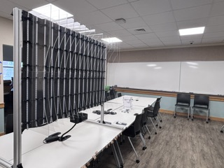
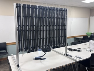
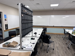
The project was intended to be installed as a semi-permanent wall-mounted exhibit in the mezzanine exhibit space of the Design, Media, and Technology department at Lebanon Valley College. Intended audiences include students, faculty, staff, prospective students, parents, and employers visiting the space. The t-slot extrusion will not be installed until early August, however, so I have instead created a free-standing display.
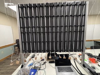
The 32 laser-cut 12" by 18" acrylic slats project outward from the wall and form a concave interactive space. A 16 × 56 NeoPixel matrix with 16 meters of Neopixels is mounted underneath, the light moves through the edge lit acrylic slats creating an interactive, immersive space.
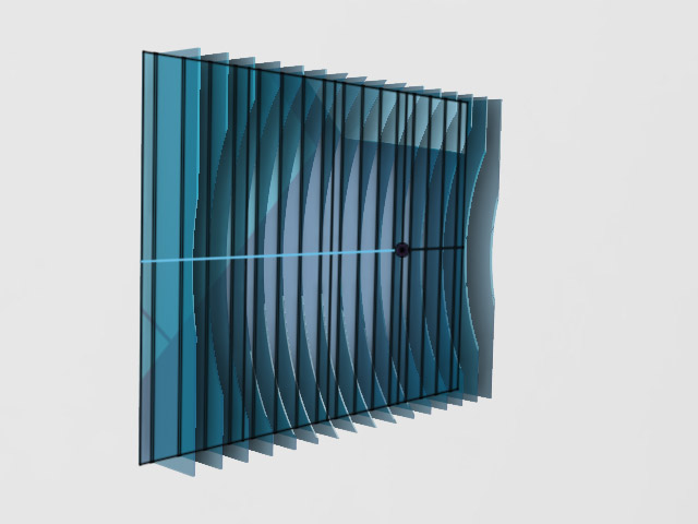
The exhibit reacts to users as they walk by, approach, stand in front of it, or walk away. The concave form is a compromise derived from the original concept of creating an immersive geodesic dome. Due to space constraints at both home and school, a full dome that I had originally proposed was impractical as the footprint for such a project would be prohibitively large. The concave form is intended to evoke a similar sense of immersion while accommodating the space available for the installation.
Ideally, the project is also intended to function as a platform that my students can later use to learn about interaction design, embedded programming for TOF sensors and neopixels/addressable LEDs, and the use of feedback systems to shape user behavior.
To demonstrate input/output device programming and embedded programming, I created a software system running on the Jeffuino board that categorizes six interaction states:
- No one present
- User approaching
- User standing still in front of the exhibit
- User walking away
- walking right to left
- walking left to right
Each interaction state will trigger a corresponding NeoPixel animation function. Sound functions using a DFPlayer Mini MP3 module may be added during a spiral if time permits.
For my system integration documentation, see my week 16 link.
For my applications and implications documentation, including what it does, who has done what before, etc, see my week 18 link.
What Have I learned?
I have really enjoyed this project and am fairly pleased with how it turned out.
Because I took this class to learn more about the knowledge and processes of a fab lab, I will start with what I have learned. I have listed a number of observations below, which I realized these last few weeks:
First and foremost, I learned that I can literally make (almost) anything (obviously within reason and the abilities of the machines in the maker space). This realization, that I don't need to choose/buy what I need, that I am not relegated to being a consumer, but am actually a maker--hell- we are all makers- is probably the most powerful take away. This is, in itself, life altering. That I write this while sitting at a desk I made during Week 7 (Computer controlled cutting), is in itself testimony to this lesson.
Second, while I knew it before, I never really "knew" how the iterative the design process actually is-- and how gradual refinements can steadily improve a project.
That being said, I've learned that having a clear version control while working is exceptionally important. I can experiment and build on ideas and go back to those ideas that worked better. This means, and it is something that the documentation requirement forced me to do, that makers need to document each iteration- identify versions (as in version numbers), specifically enumerate what works and what doesn't. This class required that I do this and while I could improve the specificity and granularity of my documentation, I found it remarkably useful.
I've learned how to run quick, throw-away prototype tests in order to test a design concept without sinking a lot of time and resources.
I've learned that when designing, I need to pay attention to how all of the elements in a system interact. I have read about systems theory, and understood it, but, like my comments on the design process, there is a difference between knowing something and "knowing" something. Case in point, I designed the enclosure to attach to 4040 T-slot extrusion. I neglected to think about the acrylic slats when prototyping. Likewise, my slat design looked nice- but didn't really accommodate assembly.
Lastly, I have learned the importance of non-permanent fasteners. Designs change...if you're doing your job. To design something that doesn't accommodate this change is, well, short sighted.
Final Project Development
I've worked on this project over the last 20 weeks, which I've listed here.
Final Project Flow Chart
Weeks 18-20 work
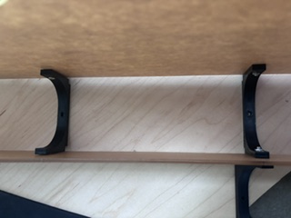
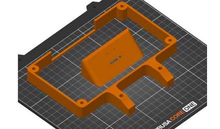
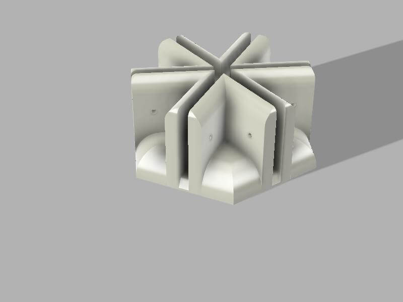
I iteratively designed the holders that I would use to affix the acrylic "slats" to the base. I worked through 11 versions before I was happy with the single holder (to be placed on the 0 and 15th slats) and then mirrored the single to create a dual holder (which would reduce the number of bolts/nuts and holes I would have to create. Design away extra steps....)
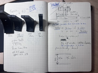
Images of holders - dual and single
Link to files
Single holderDual holder
Assembly
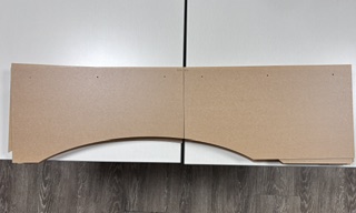
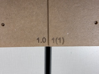
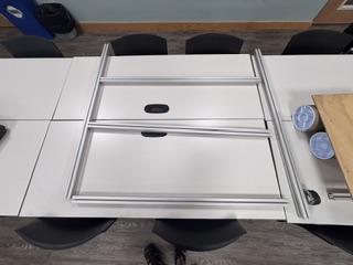
I cut and painted the base and then laser cut the 32 slats. I created IDs for each slat to understand where it goes on the base
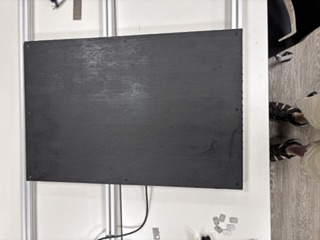
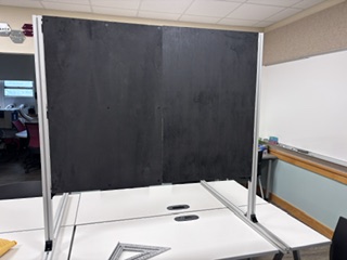
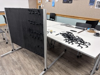
I assembled the base and had to create a t-slot exhibit- a sort of self-standing structure to which I could mount the base. Facilities in my institution advised me that they will not have the t-slot installed on the wall until early August.
I then 3d printed the 102 slat holders and then mounted the holders to the base. Before I fastened them to the base, I first mounted the holders to the base to make sure that they worked and that the slats were aligned and fit the space. So many holders.
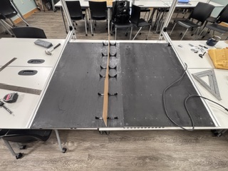
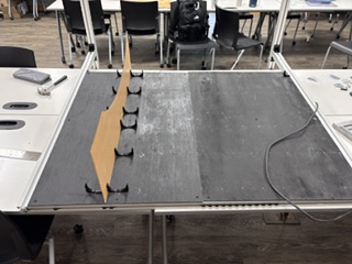
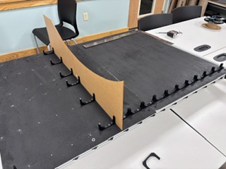
I installed the neopixels on the base along with the holders. I had estimated 60 per slat and then 58, but the number is actually 56 per slat. The materials are to be reused, which required that I change my initial plan to cut the strips into meter long strips. Instead, I will loop the neopixels, count the "dead" addresses and then program the code to avoid those addresses in the animations.
I used the holders and the acrylic slats to hold the neopixels in place- which worked well and didn't require the use of double-sided tape as I had initially thought.
I attached/mounted all 32 of the slats, (which took approximately 17 minutes per pair of slats).
![]()
I finalized the enclosure design, which involved prototyping and testing:
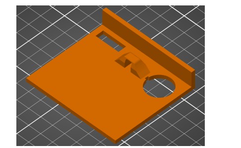
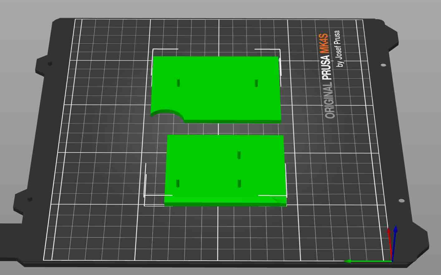
To do this, I would use the split tool in the Prusa slicer save time printing. Doing this allowed me to quickly see if the part worked as expected and allow me to quickly iterate. For instance, I tested the attachment of the enclosure to the 4040 t-slot extrusion and found that my dimensions were off (I had neglected to account for the thickness of the NeoPixel strip and the acrylic slats descending down lower than the base).
That being said, the downside to this prototyping strategy is that the parts as a whole might not reveal problems.
Excel spreadsheet of slats/columns and NeoPixel addresses (originally created by me, then modified with Codex)
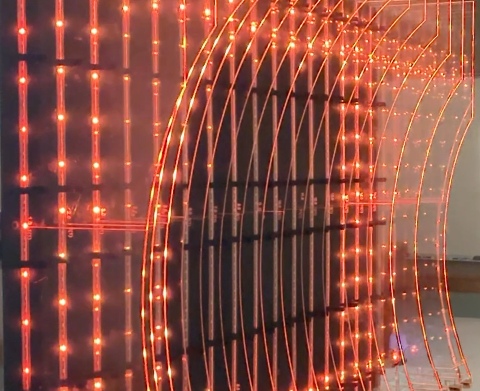
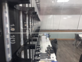
There are a lot of pixels (960) to keep track of. I numbered each of the 16 slats to correspond with the code (0-15) to aid in troubleshooting. I counted the pixels by hand under one slat and realized how laborious that process would be. When I placed the neopixels on the back and had determined that in order to reuse the NeoPixel strips I would wrap them rather than cut them, this design decision resulted in neopixels at the top and bottom that would not be usable in the animations. Rather than count each NeoPixel to determine the addresses where each slat would start and stop, I used the following prompt on Codex to create a program to test the NeoPixel addresses as I'd set them up:
I would like to have you create a program that tests the addresses of the neopixels. I will video the animation and you/we can fine tune the addresses.
I would like to have you create a program that tests the addresses of the neopixels. I will video the animation and you/we can fine tune the addresses. The pixel addresses are listed in this program. Don't change any existing programs. Instead, create a new program using version number- as in this program is version 21. In this program, the first LED in the slat is red, and the last LED in the slat is green.
link to calibration/test program
I then worked through each slat, ensuring that the program would map the correct physical start and end of each pixel column/slat, which gave me both the .eoPixel matrix addresses for my animations and also a map of the "dead" pixel addresses in the NeoPixel strings. Deadpixel address map. The .eoPixel address matrix is below.
| Slat 0 | Slat 1 | Slat 2 | Slat 3 | Slat 4 | Slat 5 | Slat 6 | Slat 7 | Slat 8 | Slat 9 | Slat 10 | Slat 11 | Slat 12 | Slat 13 | Slat 14 | Slat 15 |
|---|---|---|---|---|---|---|---|---|---|---|---|---|---|---|---|
| 55 | 111 | 167 | 223 | 279 | 335 | 391 | 447 | 503 | 559 | 615 | 671 | 727 | 783 | 839 | 895 |
| 54 | 110 | 166 | 222 | 278 | 334 | 390 | 446 | 502 | 558 | 614 | 670 | 726 | 782 | 838 | 894 |
| 53 | 109 | 165 | 221 | 277 | 333 | 389 | 445 | 501 | 557 | 613 | 669 | 725 | 781 | 837 | 893 |
| 52 | 108 | 164 | 220 | 276 | 332 | 388 | 444 | 500 | 556 | 612 | 668 | 724 | 780 | 836 | 892 |
| 51 | 107 | 163 | 219 | 275 | 331 | 387 | 443 | 499 | 555 | 611 | 667 | 723 | 779 | 835 | 891 |
| Rows 50 through 5 omitted for brevity | |||||||||||||||
| 4 | 60 | 116 | 172 | 228 | 284 | 340 | 396 | 452 | 508 | 564 | 620 | 676 | 732 | 788 | 844 |
| 3 | 59 | 115 | 171 | 227 | 283 | 339 | 395 | 451 | 507 | 563 | 619 | 675 | 731 | 787 | 843 |
| 2 | 58 | 114 | 170 | 226 | 282 | 338 | 394 | 450 | 506 | 562 | 618 | 674 | 730 | 786 | 842 |
| 1 | 57 | 113 | 169 | 225 | 281 | 337 | 393 | 449 | 505 | 561 | 617 | 673 | 729 | 785 | 841 |
| 0 | 56 | 112 | 168 | 224 | 280 | 336 | 392 | 448 | 504 | 560 | 616 | 672 | 728 | 784 | 840 |
|
Prompt:
"Create an HTML table that illustrates this NeoPixel address matrix. Cut out the middle rows but indicate that values are missing. Remove the Row column and include the prompt used to create the table."
Generated by: ChatGPT 5.5 |
|||||||||||||||
I used these addresses later in the project code to trigger the animations.
Link to updated KiCad Jeffuino (XIAO ESP32C3) reusable board file with Schottky diode
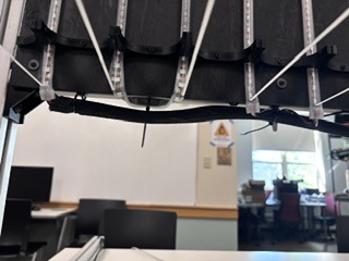
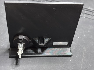
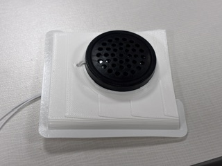
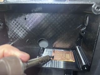
For the enclosure, I used a combination of hot glue for wires, double-sided tape, and tabs that aligned with the boards so that I could permanently attach them to the enclosure drill holes using a soldering iron. You can see in the image below the wire management bump outs that I used to attach the wires to the enclosure using zip ties.
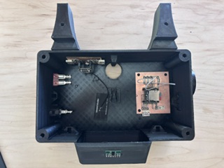
I am experimenting with the melted-post process here on an earlier prototype. Note the wire management pop outs on the sides of the enclosure.
The wire mgmt for the project on the macro level worked really well. The wire management in the enclosure was not as effective as needed. Don't use permanent means of fixing anything in projects- even when you think that they are finished. It is just a really bad idea- it makes repairing or replacing components inordinately difficult and doesn't really allow for iterative improvement.
Embedded Programming
I calibrated the sensor and worked on refining the LED animations using Codex (45 versions of the program at last count). The version that the project is running is linked here.
I had used Codex a great deal in creating the embedded programming for the project. I have set up in Codex a preference to include as a comment in the code the prompt used to create all of my programs.
Week 17 notes
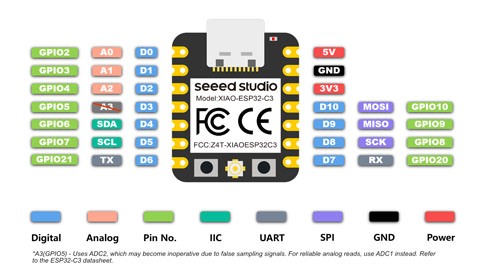
I have designed a prototype of the enclosure, wire management, and have fabricated t-slot nuts using a water jet to hold the base onto 40mm t-slot that will be used as a structure. The sensor that will trigger the animations will be a Pololu VL53L5CX TOF sensor, and the MCU will be a XIAO ESP 32 C3 board. I will like the project using 960 addressable neopixels, 16 meters of LEDs.
The sensor tracks six motion states:
- NO_PERSON No foreground object/person is detected after subtracting the calibrated empty-room background.
- STANDING_STILL A person is present, but their horizontal position and distance from the sensor are not changing enough to count as motion.
- LEFT_TO_RIGHT The detected person/blob moves across the sensor field from the viewer’s left side toward the viewer’s right side.
- RIGHT_TO_LEFT `The detected person/blob moves across the sensor field from the viewer’s right side toward the viewer’s left side.
- APPROACHING The detected person/blob gets closer to the sensor over time.
- WALKING_AWAY The detected person/blob gets farther from the sensor over time.
This is the sketch that was created
linkIt currently is not registering my approach (standing still seems to be the default) and doesn't seem to register when I move my hand from left to right or right to left in front of it.
I worked with codex to create this program.
We determined that the default is standing still- when it should be no person. the sensor is tuned so that it recognizes movement in the 8x8 grid-
The process in the program is that it scans a raw 8x8 depth grid and then calibrates by "subtracting"the empty-room background. After it calibrates, it will find foreground body/person zones and estimate X and y positions and z distance in order to classify motion state.
Initially, the code inferred these motion states from two values: x = horizontal position across the 8x8 grid, and z = distance/depth from the sensor in millimeters So side-to-side motion comes from changes in x, and approach/retreat comes from changes in z.
Just using z / distance created problems as it has a lot of noise. I decided to use by changes in z and the number of zones as a means of tracking approaching and walking away. As an object/person gets closer to the VL53L5CX, two things should happen- the z distance decreases (as the the measured distance in millimeters decreases) and the number of foreground zones should increase (the person takes up more cells in the 8x8 grid).
I gave codex the following prompt: Would it be more effective to revise the sketch to use both x and z values as well as zone count as a means to calculate the six motion states?
Sketch VL53L5CXTOFScanner8x8grid_distandzonecount_v5The code does a better job at identifying approaching and walking away, but doesn't do a great job identifying left to right/right to left movement. if the user is walking at an angle- where they are passing the sensor but are coming closer to the sensor, the program confuses RTL or LTR with approaching. I had instructed it that side-to-side movement should win whenever distance movement is clear. Approach/walk-away should mainly describe movement where the person’s x position is relatively stable.
The project worked well at mapping movement. Now to connect animation sketches to the motion states.
This is the prompt that I used with Codex. I uploaded the LED animations from week 4 embedded programming.
"now create a sketch that takes the six motion states and maps them to a NeoPixel pattern. I've attached four sketches of NeoPixel patterns as an example. When the person is standing still- I want the breathing sketch. Movement should be two new sketches- lighting up the 16 slats of 60 neopixels in the direction of movement. traveling tails can be moving from high #LED to low # led when viewer approaches (the LEDs are moving down) and when the view moves away, the LEDs move up (low to high). The excel spreadsheet will be the address of each .eoPixel in the LED matrix. bottom left is the origin.""
I included the sketches and files from week 4 and
LEDMatrixConcept excel fileI worked through eighteen versions of this software. The Eighteenth version used the following prompt:
"Revise VL53L5CXTOFScanner8x8grid_distandzonecount_neopixelpatterns_V7.
  Keep the six VL53L5CX motion states and the 16 slats of 60 NeoPixels on D7.
  Improve the user experience and power behavior. NO_PERSON should invite
  interest and movement toward the exhibit by moving lights from the four
  corners of the LED matrix toward the center. The NeoPixel system is powered
  by a 10 amp supply, while 960 NeoPixels at full white could require about
  57 amps, so do not use white or full brightness. Keep all patterns low power,
  use mostly one or two color channels, and avoid lighting the full matrix at
  high intensity. Include this prompt in the header comments for Fab Academy
  documentation.

  Version 9 revision:
  Create a new version in which the program only lights every third NeoPixel in
  all animations. Apply this as a global power-saving rule so the attract mode,
  breathing pattern, left/right slat sweeps, approaching tails, and walking-away
  tails all obey the same every-third-pixel limit.

  Version 10 revision:
  Revise the APPROACHING animation so that the display gradually turns on more
  lights as the viewer gets nearer to the sensor. Keep the global every-third
  NeoPixel limit for power safety, avoid white, and scale the fill amount and
  brightness from the measured z distance.

  Version 11 revision:
  Add a global maximum brightness cap so no color helper can request more than
  half of the possible 8-bit brightness value. This keeps every animation at or
  below 127 out of 255 before the NeoPixel library's global brightness scaling
  is applied.

  Version 12 revision:
  Add a one-second delay before publishing STANDING_STILL. Brief pauses during
  approach, walking away, or side-to-side movement should not immediately switch
  the display into the standing-still breathing animation.

  Version 13 revision:
  Add explanatory comments throughout the program and create a companion HTML
  document that identifies each major part of the program and explains how it
  functions.

  Version 14 revision:
  Reduce false STANDING_STILL classifications when no person is present. Add a
  stronger foreground requirement for standing still, track how long a valid
  foreground person has been present, and force weak still detections back to
  NO_PERSON instead of allowing small background noise to become STANDING_STILL.

  Version 15 revision:
  Make the NO_PERSON attract animation more visible and inviting while keeping
  the every-third-pixel and half-brightness safety rules. Replace the subtle
  corner comets with broader corner-to-center fan waves plus a soft center pulse.

  Version 16 revision:
  Revise the NO_PERSON default animation so it starts from the full perimeter of
  the LED matrix: slat 1, slat 16, the top row of every slat, and the bottom row
  of every slat. The spreadsheet and Arduino code now use zero-based addresses,
  so the visible top row is 59, 119, 179 ... 959 and the bottom row is
  0, 60, 120 ... 900.

  Version 17 revision:
  Make the movement animations more seamless and directly controlled by sensor
  values. LEFT_TO_RIGHT and RIGHT_TO_LEFT now use smoothX to place the lit slat
  band, so reversing direction moves the band back instead of restarting a
  canned sweep. APPROACHING and WALKING_AWAY now both use the same smoothZ depth
  fill, so walking forward fills the display and backing up removes the fill.

  Version 18 revision:
  Make approach and walking-away easier to see by dividing the depth interaction
  into 20 visible steps, matching the 60-pixel slats with the every-third-pixel
  power rule. The depth fill amount is based mostly on distance from the sensor
  and partly on foreground zone count, so moving closer and taking up more of
  the VL53L5CX grid both increase the number of lit levels."
Mounting
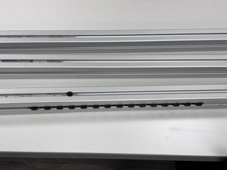
I was initially to use four foot lengths of permanently mounted T-Slotted Framing Rail, Single Four Slot Rail, Silver, 40 mm Square as the base. This is meant to be a permanent installation that will afford displaying other interactive projects in the future. (Facilities was unable to install the mounts in time for this class.)
Week 14 notes
I am working on the sensor that will trigger the animations. I am experimenting with either a time of flight sensor or the XIAO ESP 32 sense board and using tensorflow. In addition, the weight of the project is enough that it would need a solid foundation. I will work on creating a mounting system using T slot that can be mounted to a wall that would accommodate an 18 x 24 modular panel.
When I design and cut the pieces of the assignment, it will be hard to determine which boards are which. When fabricating the pieces, I will need to clearly yet unobtrusively identify each piece.
In addition, I will need to change the MCU that will control the Neopixels in the project. The XIAO RP2040 doesn't have WIFI capability. I will instead use a XIAO ESP32C3 or ESP32S3-Sense. I can use the following resource to control the neopixels from the esp32:
Lily. “Control Your NeoPixel LEDs with WLED and XIAO ESP32 MCUs.” Latest News from Seeed Studio, May 6, 2024. https://www.seeedstudio.com/blog/2024/05/06/exciting-update-wled-now-supports-xiao-esp32-mcus/.
Weeks 11-12- Rethinking the Final Project
I thought the geodesic dome concept was interesting, however the problem is that to make the form factor of the geodesic dome large enough for someone to walk inside of it, the project would require a footprint too large for any space that I currently have at my institution. As a result, I needed to rethink what the form factor of this project would be.
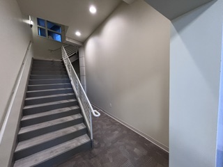
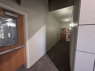
Because horizontal space is such a constraint on my campus, the idea of using vertical space is appealing, as there are a number of spaces such as stairwells or hallways in which I could mount this project.
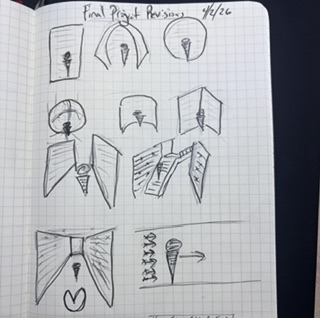
As a result, I decided on focusing on a vertical form factor, as that would not take up any horizontal space. I brainstormed a number of different ideas, and for the first spiral, I think I’m going to do just one wall.
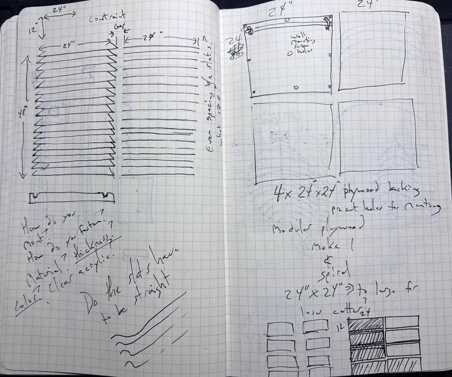
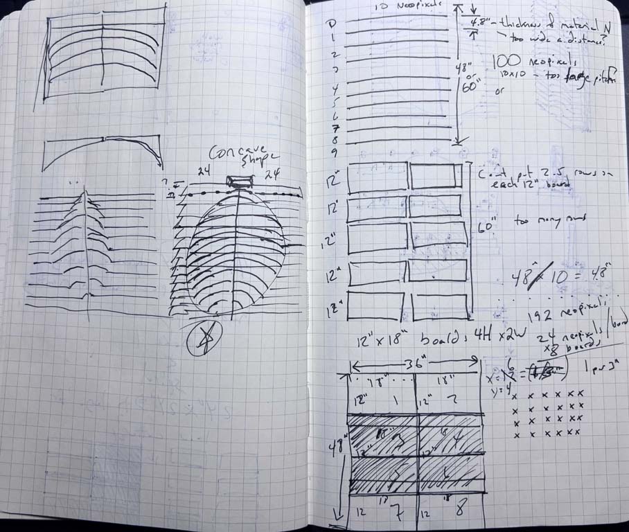
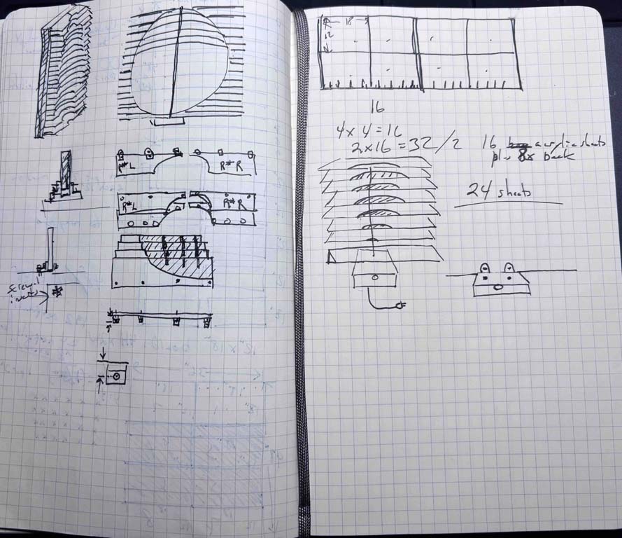
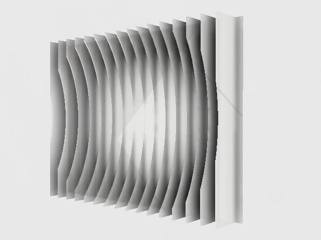
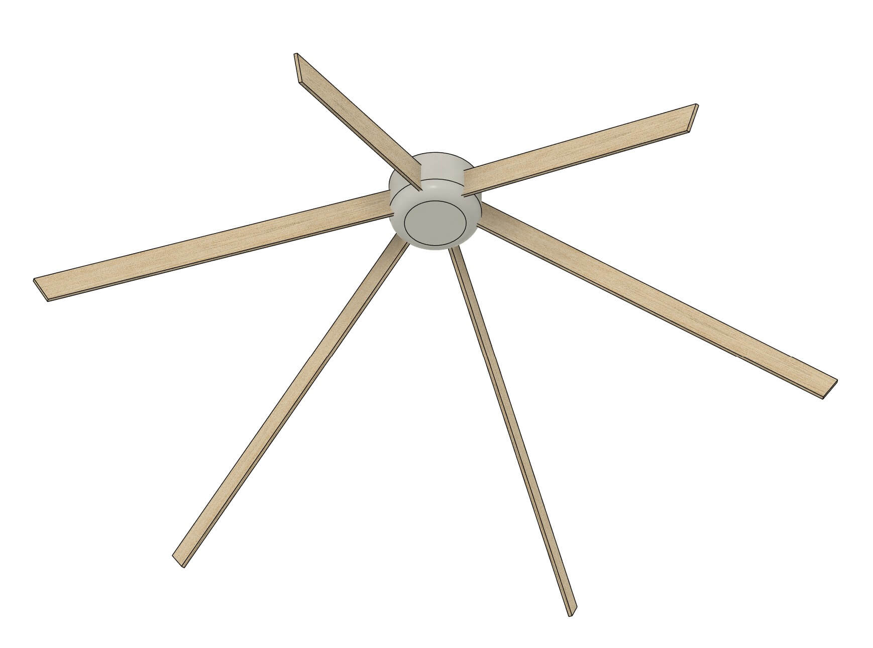
The new form factor of my final project will look something like this:
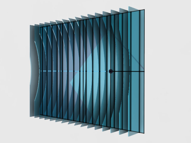
The LEDs will be mounted along the edges of the cut acrylic, with the microprocessor, sensors and audio/mp3 player mounted at the base of the installation.
To build out this project, there are a number of different components that I’ll need to consider. The first is the mount. I will need some means of mounting the project to a wall. I’ll need some means of creating a space to hold the LEDs and the mini MP3 player and speaker, as well as the microprocessor. I’ll need to be able to run wiring from all of the different power source and micro-controller and LEDs to one another. I am going to opt to use quarter inch, 12 by 24 inch acrylic sheets, and laser cut the form. I would like to use the idea of a concave surface with LEDs and a speaker mounted on it. I believe I will mount the speaker on the bottom to make it closer to the power source. I think I’m unsure of the material used to mount the pieces to the wall. Acrylic would be nice, but it does pose some problems in terms of seating the bolts that would hold the slats on. I could 3D print, using a stronger material such as PETG, the mounts that would hold the acrylic sheets to the back plate. The back plate would be a series of 12 by 24 inch sheets, essentially. I will continue to use the laser cutter. Obviously, I will create the microprocessor using the desktop mill. I will be using outputs in the mini MP3 player playing music and a set number of animations that the LEDs would perform as responses to user behavior. I will use some type of sensor to capture motion or movement--or color. If there is time, I am entertaining the idea of using some type of computer vision, which could provide some really interesting means of interaction.
I will likely use some of the patterns from the embedded programming week.
breathe
Final Project Task List (Weeks 12–20)
-
Finalize Scope and Constraints
- Get instructor/evaluator signoff on finalized design and concept- (36 × 48 inches) and modular layout (eight units (12" × 18"))
- Select input sensor/s (motion sensor, distance sensor, or camera)
- Finalize design of concave surface and layout of LEDs, microprocessor and speaker
-
Backing/Mount Design and Planning
- Source materials (acrylic sheets, PETG filament, fasteners)
- Create CAD files for all structural components (modules, mounts, backplate)
- Plan mounting system (wall attachment, module-to-backplate connection, electronic components, and microprocessor)
-
Electronics and Power
- Calculate total power requirements for total LEDs, microprocessor, and electrical components
- Order appropriate power supply
- Plan wiring layout and cable routing across modules
- Plan power distribution (injection points, routing, safety)
-
Programming
- Develop initial code (LED behavior routines, sound playback, input triggers)
- Code input sensor(s) on microprocessor
-
Prototype
- First prototype - cut in cardboard
- Second prototype - cut Fabricate one complete 12 × 18 module (laser cut, printed parts and electronics/mounts)
- Assemble structural components for the module
- Wire LEDs, micro controller, speaker, and power
- Implement input sensor/s on the module
- Test full functionality of the single module
- Revise design based on prototype results
-
Fabrication
- Laser cut all acrylic modules and backplate components
- 3D print all mounting brackets and supports
- Fabricate or mill any custom PCB components
- Prepare all structural parts for assembly
-
Electronics and Integration
-
Test final code for:
- Input-sensor and triggered behavior
- LED animations
- Sound playback
- Wire all modules (LEDs, power, audio, control lines)
- Integrate input system across full installation
- Implement full power distribution system
-
Test final code for:
-
Assembly
- Assemble full 36" × 48" structure
- Mount modules to backplate
- Install speaker and audio system
- Secure and organize all wiring
-
Testing, Calibration and Debugging
-
Test subsystems individually:
- LEDs
- Audio
- Input
- Test integrated system behavior
- Test power stability and heat considerations
- Perform user interaction testing
- Revise and refine behavior and structure
-
Test subsystems individually:
-
Installation and Finalization
- Finalize wall mounting method
- Install installation in context of use
- final structural and aesthetic adjustments
-
Documentation and Presentation
- Document process (design, fabrication, electronics, interaction)
- Capture photos and system diagrams
- Create project video demonstrating functionality
- Create presentation slide summarizing project, process, and outcomes
- Prepare final submission materials
Week 10 progress and questions
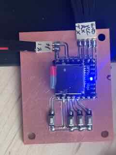
I built out an LED PCB and a mini-mp3 player PCB for this project.
light
I used the NeoPixel addressable LED from week 10.
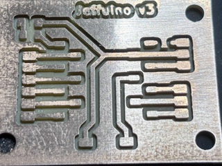
Each board requires a capacitor across voltage and ground and the tutorial on Adafruit recommends a resistor on the first digital in of a NeoPixel string. That being said, because the resistor only needs to be in series with the first NeoPixel it would be pretty wasteful to add resistors to every board AND would add up (80 330ohm resistors would create a lot of problems for the circuit by adding that much unneeded resistance). I decided to redesign the jeffuino (now v3) to include a 330 ohm resistor on the d6 pin. This would keep the PCBs modular and allow me to add the resistor easily.
Going forward, I will need to think about how to run the data and the 5V power across all 80 some LED boards. The current setup doesn't really allow for running data in a "net" nor does it allow for adding multiple instances of five volt power to the neopixels throughout the net of LEDs.
Sound
Mini-MP3 player, using the DFROBOT DFR0299 DFPlayer Mini MP3 player.
I began to work through the project and build out a BOM. A 5/9th geodesic dome that would allow a person to stand inside it would have a diameter of 4 meters/13 feet. My campus has little space that would accommodate such a footprint. It would present ADA and safety concerns.
To build a 3v 5/9 geodesic dome that is 2.375 meters tall (7.79 feet), would require 83 total struts (requiring 131 meters or 430 feet of material for the struts) and 61 connectors. My campus has limited space indoors to place this and my goal had been to make something that would be a permanent installation.
- The installation of the project can’t impede movement and must accommodate building/fire codes.
- Has to allow for power
- Can’t pose a safety hazard
- Should convey how to use it
- I have concerns about power and the safety of the circuits I design.
The form of a geodesic dome is likely not a viable option for this project, given the space and material requirements that it wold pose. As a result, I will need to rethink the form. The goal is to immerse the user in the experience through providing both visual and auditory feedback stemming from user actions. The form factor that this could take could be slightly different, yet allow for the constraints listed above. I began to brainstorm alternate form factors for the assignment, listed below.
Week 8- Questions I need to answer
Fabricating and assembling the electronics for my final project will pose a number of problems.
-
Quantity. If the dome has an LED in each hub in the dome, I will need to fabricate, solder, attach to the dome, and then connect in a series approximately 80 LED PCBs. Each LED PCB would need an addressable LED, a capacitor across voltage/ground, and a means of daisy chaining (input and output). I need to determine the best means of creating 80 small boards. One solution I have is based on the tabs created when cutting using the CNC. Adding tabs that don't get cut all of the way would allow me to create an entire sheet of semi-attached PCBs that I can break out as I fabricate and use them.
-
Ease of assembly / daisy chaining. I need a means of connecting and disconnecting the LED PCBs to one another for power and data. This would likely involve connectors on the boards themselves and easily attachable and detachable wires, or some other way to connect each board.
-
Sequencing. I had not thought about how the PCBs and LEDs would be connected in the dome. Initially, I had just thought that the LEDs would be connected in a series, but that might not be the optimal way to do so. Is this a line running around and up the height of the dome, like an inclined plane wrapped around a screw, or is it some other pattern? How I connect the LEDs will likely affect the programming and the overall effect of the lights in the experience. Do I arrange them as a series of concentric circles going from the base to the top, or is there some other means of arranging the LEDs? I will likely need to explore this in the outputs week.
-
Power. I am a little rusty in this area. I will need to figure out how to power 80 LEDs, plus the micro-controller or board I will make, plus the means of input for the whole experience. I assume I will need to figure out the forward voltage drop and current used by each LED. I also think that I will likely need to use multiple power sources at different points in the LED net rather than just one running through the length of the LED circuit.
-
Input. My initial idea was some form of sensor that would collect input on user actions in the dome and, based on this input, change what the LEDs do. I need to begin to think about what sensor would make the most sense, how this sensor would shape the user experience so that it is desirable, and clearly map user inputs to the corresponding sensory outputs provided by the LEDs, and possibly sounds. I will work on this in inputs week.
-
Struts. I do not think it practical to CNC struts for this project and think, right now, that PVC tubing might be a better solution. The biggest issue is that the CNC and the node are 7.5 hours away. If I make a mistake or need to fabricate new struts, I have a problem. In addition, I am unsure if cut plywood would be structurally able to support the weight of the dome. PVC tubing would be lighter and the circular cross section of a PVC tube might be stronger It seems that I need to explore the question of what would make for the most cost-effective means to create struts for this project. The strut design will in turn shape the redesign of the hubs.
-
Hubs. I have a rough concept of the hubs now, but I need to determine a design that will hold the weight of individual struts and the dome itself. I can use PETG to make it a little tougher. I can lighten the weight of the struts. I know that a dome will have slightly different angles for each of the triangles in the geodesic dome: the internal angles of the triangle and the dihedral angle of the planes. The hubs will need to be slightly different, some with five intersecting struts, some with four, and account for the different angles.
-
Form. I need to design the dome in such a way that the form allows people to enter and exit. Given the size of the project, I might need to rethink the dome being placed on the floor, such as placing it on a ceiling or in a corner. I have to figure out what this dome will look like in the context in which it will be set up. This will in turn affect the design of the struts and hubs and the placement of the input sensors. I need to determine the viability and feasibility of the existing design in terms of the context in which it will be located and work through how I can design the user experience of the project to best accommodate the space. This might require changing the scope or concept of the work.
-
Research and work through the project in order to get a better understanding of how users would enter/move through it/engage with it and any ADA requirements that might need to be accommodated. Some of these questions will be answered during the input and output weeks, but how they use it will shape the design.
-
Wire management. I need to determine how this project will manage the different wires required for it to work. I need to address power and data for LED PCBs, power for the main controller, and power and data for input sensors. The wires could be attached to struts or run through the struts if hollow. What makes the most sense for fabrication, setup and assembly, and the overall user experience?
Week 6 - electronics design
During week 6 I wanted to simulate a NeoPixel circuit similar to what my final project would use. Image of board forthcoming.
The Neopixels require a higher voltage and ampage than the RP2040 can provide. I will need to power the NEOPIXELs using an external power supply rather than through the Vout of the RP2040 as the RP2040 only provides 3.3 v through its GPIO pins. In addition, the neopixels data line also requires a higher voltage than what is provided by the RP2040. For the final project I will likely need to add a logic converter. (I need to look at the data sheets of the neopixels and the XIAO/RP2040 to gather more details on forward voltage drop, current, etc). The NeoPixel in the simulation was not very bright, but did flash as expected. As an experiment, I had tried running the vdd and vss from the board to each NeoPixel and daisychaining the data through a series of neopixels. Both appeared to work in the simulation. Good to know. For my final project, I will research whether I can daisychain power, ground and data or whether I need to power sections of the LEDs separately.
The link to the sketch is: https://wokwi.com/projects/457408666709350401
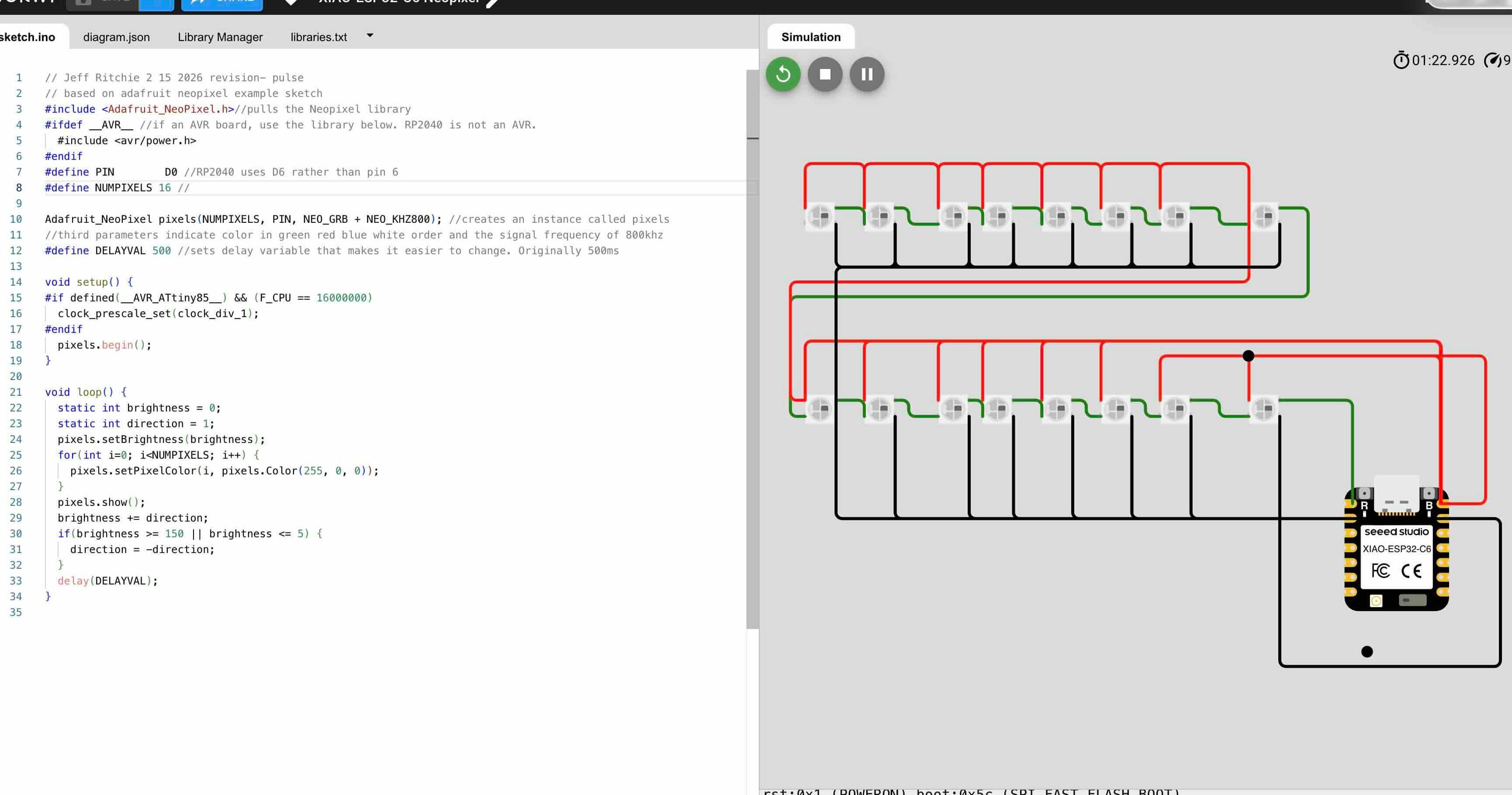
For week six our task was to design an embedded microcontroller system and check its design rules for fabrication. Based on the results of my simulation, I had intended to design a simple board that affords a "daisy-chainable" NeoPixel circuit that would easily connect with other NeoPixel circuit boards and provide the required capacitor between ground and power. The requirements of this week's assignment mean that instead I would need to build a microcontroller- not this LED board I had initially considered. I used an XIAO RP2040 and built it out to allow for inputs/outputs on the board. I will likely use this board (or one using an RP2040) for my final project.
Week 2- Preliminary Designs
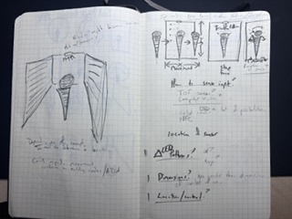
In week two I began working through the design of a geodesic dome.
My initial design concepts for the hub include the following:
Early Concept work
The user would shape the colors, patterns and sounds through either movement (registered by a sensor in a hub at the top of the dome), RFID tags to choose the patterns, or possibly a mobile app.
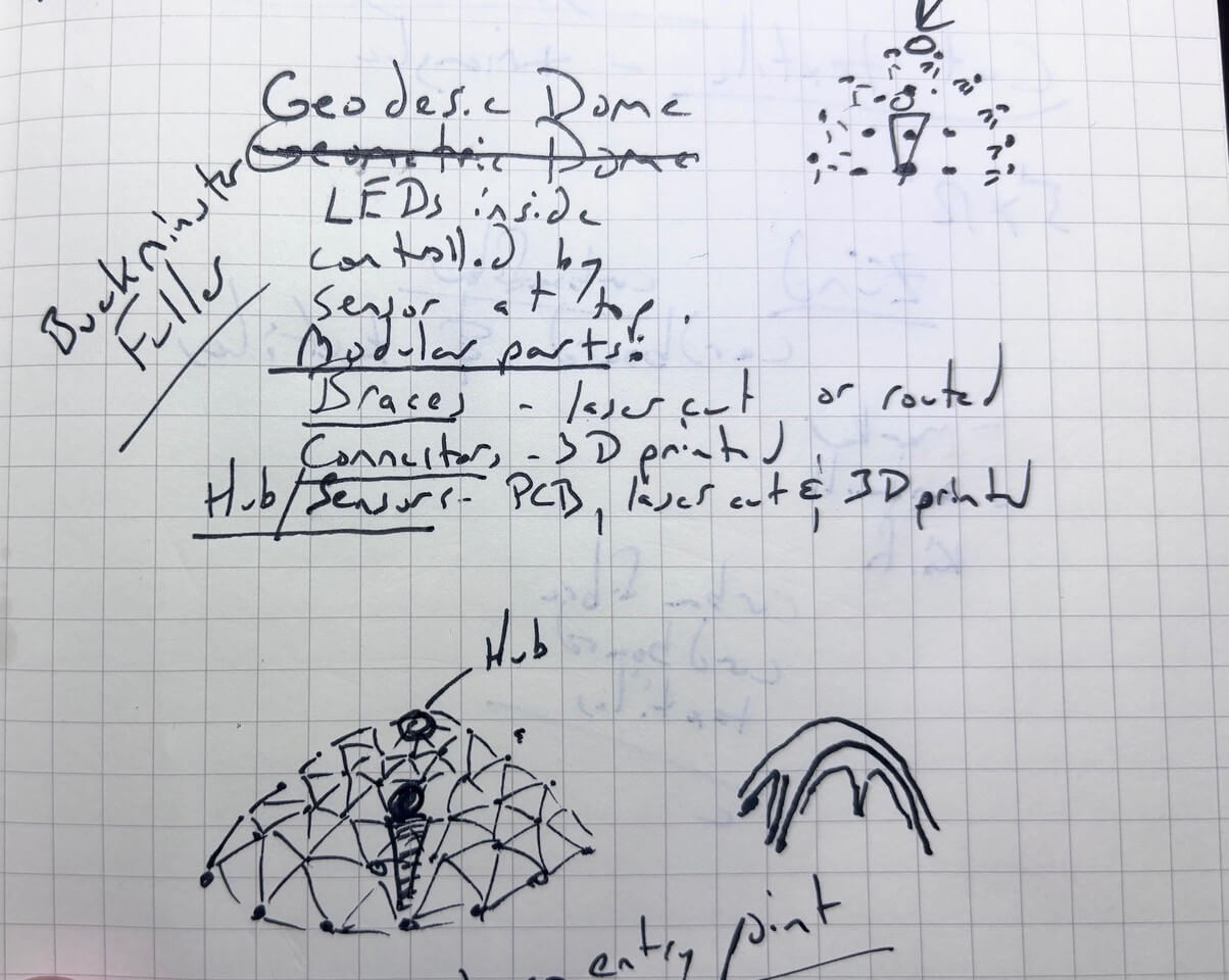
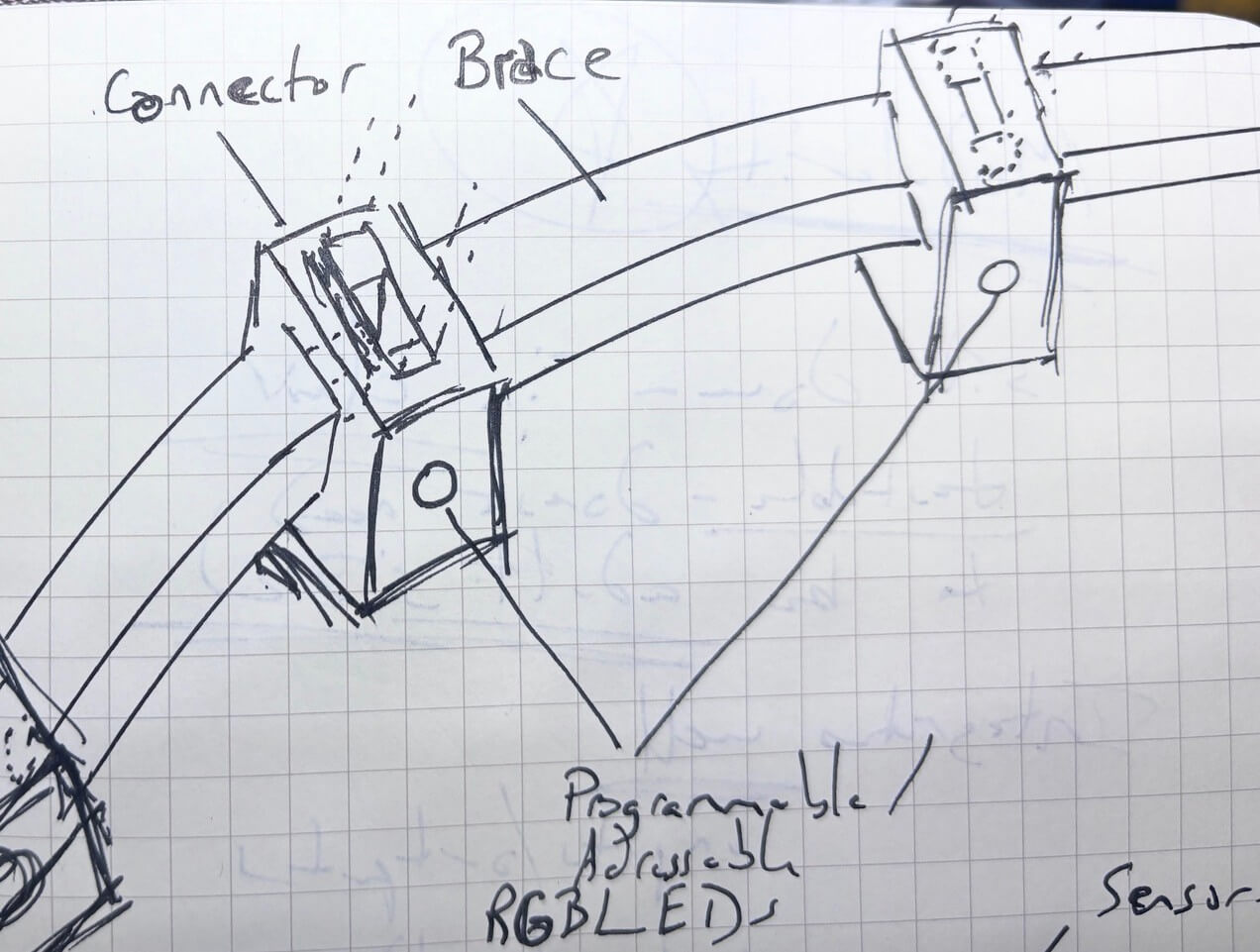
The project would be composed of three parts- the hub which contains the sensors and the braces and connectors, which would be modular.
Brainstorming
To come up with this idea, I worked through the posted earlier projects, listing those that I found interesting. I then used chatgpt 5.2 to categorize earlier fab academy projects. My initial prompt was:
“You are a student taking the fab academy class. You want to categorize the different projects that have been made in previous classes, with the aim of understanding what is possible in the class, given the technologies taught, areas in which successful projects seem to focus, and as a means to brainstorm your own project. The URL for the class is https://fabacademy.org/2026/prior.html”
The engine asked me a few questions for clarification- I've prompted the engine to always ask me questions to clarify the context and intent. The link to the chat is here. There are some serious problems with the links it provided, but the goal was to help me start considering what is possible given the technologies taught and brainstorm ideas.
I then used listing and free association for about an hour to brainstorm possible project ideas or problems that I would like to solve. I reviewed the list to see if any interested me and wrote them out separately for further elaboration. I had about ten possible ideas that I could pursue.
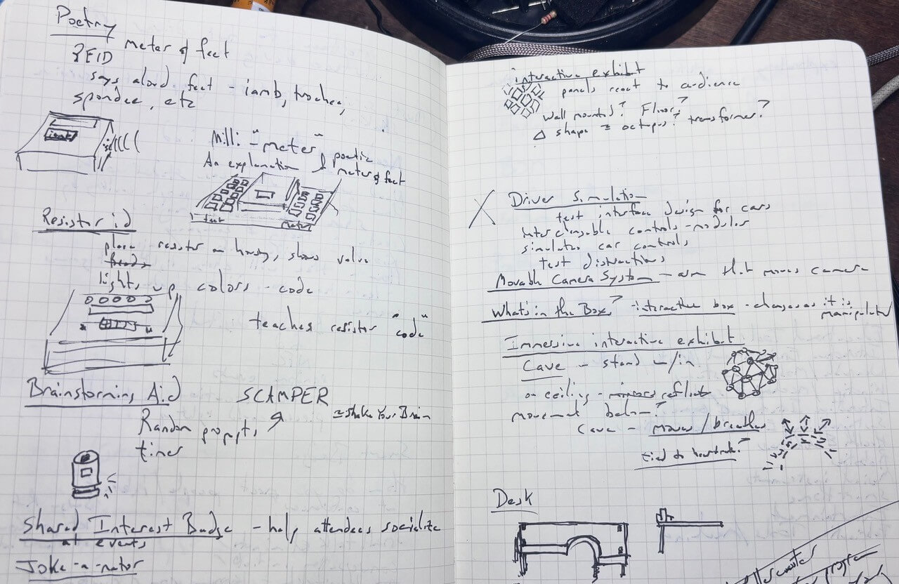
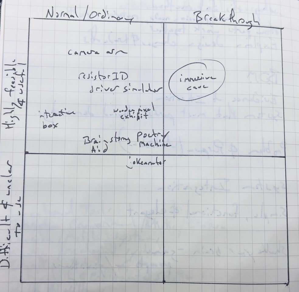
To refine the list, I thought about how I could evaluate this semi-final list of topics. I remembered an evaluation tool on choosing ideas in a book on brainstorming and creativity (p. 181) - Keith Sawyer, Zigzag. Jossey Bass, 2013.amazon link here- not a plug. This book explained how you could plot your ideas on a matrix:
| Normal/Ordinary Ideas | Breakthrough ideas | |
|---|---|---|
| Highly feasible and useful | Not so original ideas that are highly feasible- Ideas that might be worth pursuing but would require an effective and efficient implementation plan | Ideal concepts- build it. |
| Difficult to make and unclear use | Not so original ideas that are not feasible. Throw it out. | Very original ideas that are not feasible- would need to be really high value/importance to proceed |
I plotted out my ten ideas and the geodesic dome concept appeared to be the concept that would be best suited for this project.
Bill of Materials (BOM)
| Component | Quantity | Supplier | URL | Price |
|---|---|---|---|---|
| Exhibit | ||||
| Acrylic (Clear) 12” x 24” x 1/8” | 16 | MakerStock | link | 8.50 |
| Backing/Mount Structure | ||||
| Plywood ¼ in 24" x 36" | 2 | Lowes | no link | 11.29 |
| T-Slotted Framing Rail, Single Four Slot Rail, Silver, 40 mm Square, 4 Feet Long (mounted on wall) | 3 | McMaster Carr | link | 40.22 |
| M3 6 mm bolts/nuts/washers | ||||
| T-slot nuts | ||||
| PETG (1kg spool SUNLUU) | 1 | Amazon | link | 14.43 |
| NeoPixel addressable LEDs | ||||
| Adafruit NeoPixel Digital RGB LED Strip - Black 60 LED 4m | 4 | Adafruit | link | 54.95 |
| Female DC Power adapter - 2.1mm jack to screw terminal block | 1 | Adafruit | link | 2.00 |
| 2-pin JST SM Plug + Receptacle Cable Set | 15 | Adafruit | link | 0.75 |
| User Input sensors | ||||
| VL53L5CX Time-of-Flight 8×8-Zone Distance Sensor Carrier with Voltage Regulator, 400cm Max | 1 | Pololu | link | 19.95 |
| MCU/Processing | ||||
| XIAO ESP32C3 | 1 | digikey | link | 4.99 |
| Sound (built in but for future spiral) | ||||
| DFPLAYER - A MINI MP3 PLAYER DFR0299 | 1 | digikey | link | 5.9 |
| 36mm Speaker w/ Wires - 8 Ohm 2 Watt | 1 | Adafruit | link | 1.95 |
| SD Card | 1 | Amazon | link | 31.99 |
| Power | ||||
| 5V 10A switching power supply | 1 | Adafruit | link | 29.95 |
Files for my Final Project
Files for the acrylic slats- in two pieces
- 1_Faces.svg
- 1_Faces.svg
- 2_Faces.svg
- 2_Faces.svg
- 3_Faces.svg
- 3_Faces.svg
- 4_Faces.svg
- 4_Faces.svg
- 5_Faces.svg
- 5_Faces.svg
- 6_Faces.svg
- 6_Faces.svg
- 7_Faces.svg
- 7_Faces.svg
- 8_Faces.svg
- 8_Faces.svg
- 9_Faces.svg
- 9_Faces.svg
- 10_Faces.svg
- 10_Faces.svg
- 11_Faces.svg
- 11_Faces.svg
- 12_Faces.svg
- 12_Faces.svg
- 13_Faces.svg
- 13_Faces.svg
- 14_Faces.svg
- 14_Faces.svg
- 15_Faces.svg
- 15_Faces.svg
- 16_Faces.svg
- 16_Faces.svg
- holderv11-1cm_thick.3mf
- holderv14dual.3mf
- enclosure
- enclosure lid with no handle
- Program that converts movement and distance from TOF and activates LED patterns
- NeoPixel Address Calibration Program
- 4040 T-Slot Washer (which should be cut in steel and have at least three threads)