Week 16 System Integration
In this week, we were charged with the following assignment:
Design and document the system integration for your final project
My first task – define what system integration means.
I began by working through the links and readings.
For the last ten years, I have been teaching UX, IXD, and usability, so the initial discussion of design is a good fit for me. I want to take the class, how to design almost anything.
What system integration means
Based on my lecture notes and the week’s class page/links, I believe that system integration means:
Understanding all of the elements that go into system and how they go together – or, what are the parts and how do they become a system. For this week, this means to create a map of all of the hardware and software components.
Designing the project to effectively accommodate the methods of fabrication being used and minimize the work or processing that is involved in finishing and assembling the parts and components to build the system
Designing the project to minimize the chance of failure of the project as a whole and its constituent parts. For instance, this would mean I should design a PCB to be modular- with external headers to connect to sensors and actuators
It also means designing the enclosure for the project as a whole, so that the parts are:
- Protected – secures/mounts components and wiring to ensure that the components perform their designed functions and protects against different possible failures.
- Unified
- Visually appealing
- Convey purpose, function, and use where appropriate.
First steps
Revised structure- I revised the structure of the exhibit and tried to understand how all of the parts would fit together.
One determination that I made in part due to this week's lecture, was that the 6mm thick acrylic is too thick/heavy, that to minimize stress on the acrylic, the orientation of the acrylic strats needs to be vertical (perpindicular to gravity). go with 3mm
Sourcing materials- Because I am remote, my node is approximately 8 hours away, and my home institution's lab doesn't have relationships with vendors who can supply the materials in the fab academy inventory, I identified the amount and qualities of the materials that I need to complete my project and then identified vendors (ideally local) who could supply these materials.
Need to consider the end of life- Parts should be able to be repurposed in the lab.
Need to consider the use of space- the design should allow for easy assembly and dissambly and be fairly modular in nature.
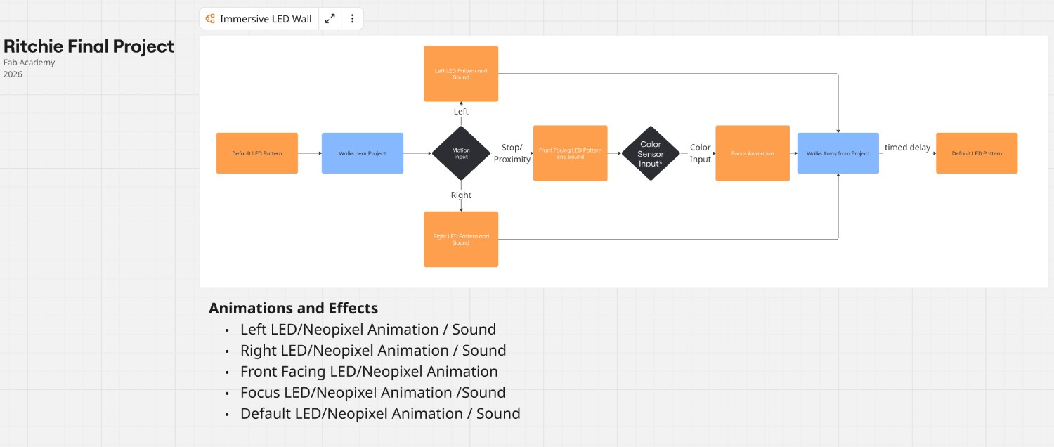
Final Project Flow Chart
System/Parts
The system I am building is an interactive exhibit in which user movement will cause the NeoPixel patterns to change. It is comprised of the following parts:
- Exhibit “dome”
- Backing/Mount Structure
- NeoPixel addressable LEDs
- Enclosure
- Electronic components
- User Input sensors
- MCU/Processing
- Sound (second spiral)
- Power
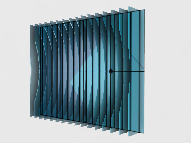
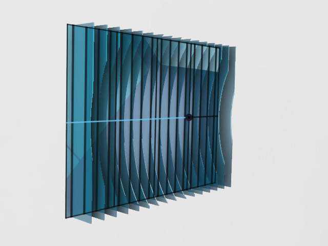
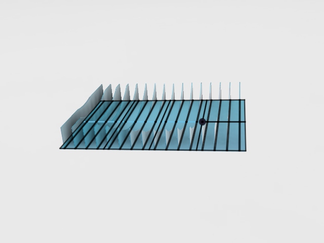
Exhibit “Dome”
The exhibit will be vertically mounted slats on a wall, with the laser cut acrylic slats channeling the light from the LEDs placed beneath them. The exhibit is 48” x 36” total dimensions, comprised of 32 x 12” x 18” x 1/8” acrylic pieces. The acrylic will be cut to form a “dome.”
Design for fabrication The parts are designed to fit inside the bed of the epilog laser cutter in my lab (12x24 in).
The slats have a prescribed order and will have an identifier laser engraved unobtrusively in a lower corner of the piece to aid in assembly.
Files to be laser cut -Forthcoming
Base/Mount Structure
The exhibit will require both a base to hold the slats as well as a permanent structure to mount to the wall and hold the base.
Base
The Base will be comprised of both a base structure and holders on which to mount the slats.
For the base I will likely use ¼” plywood cut into 12x24 sections, painted black.
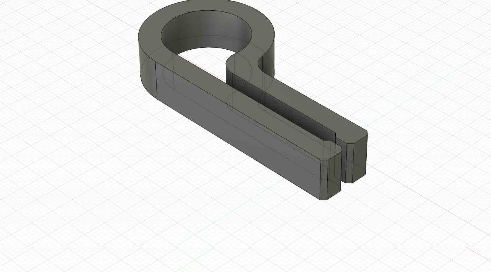
Holders
I will fabricate holders as a means to mount the slats on a base and then mount this base to the wall. The holders are designed to be unobtrusive, readily hold the acrylic perpendicular to the base, allow the LEDs mounted below the acrylic to shine through, and be sturdy enough to take light brushes/bumps.
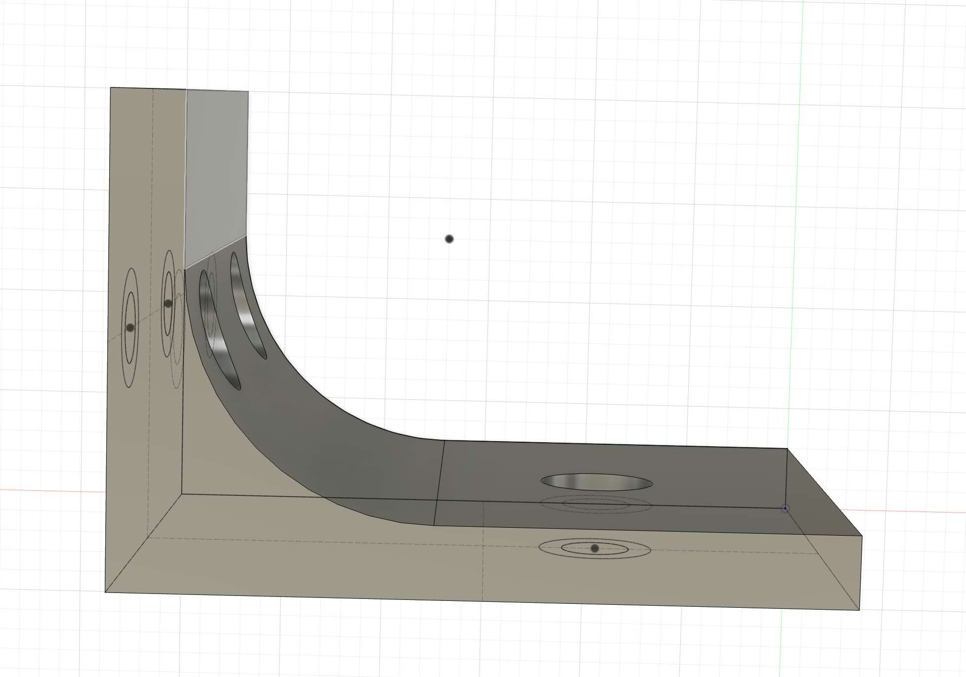
File- 3mf of holder-draftv2
Mount Structure
To mount the base, I need to design a permanent fixture that can be secured to a wall and that will allow my interactive exhibit –and other/different projects --to be securely yet temporarily mounted to it.
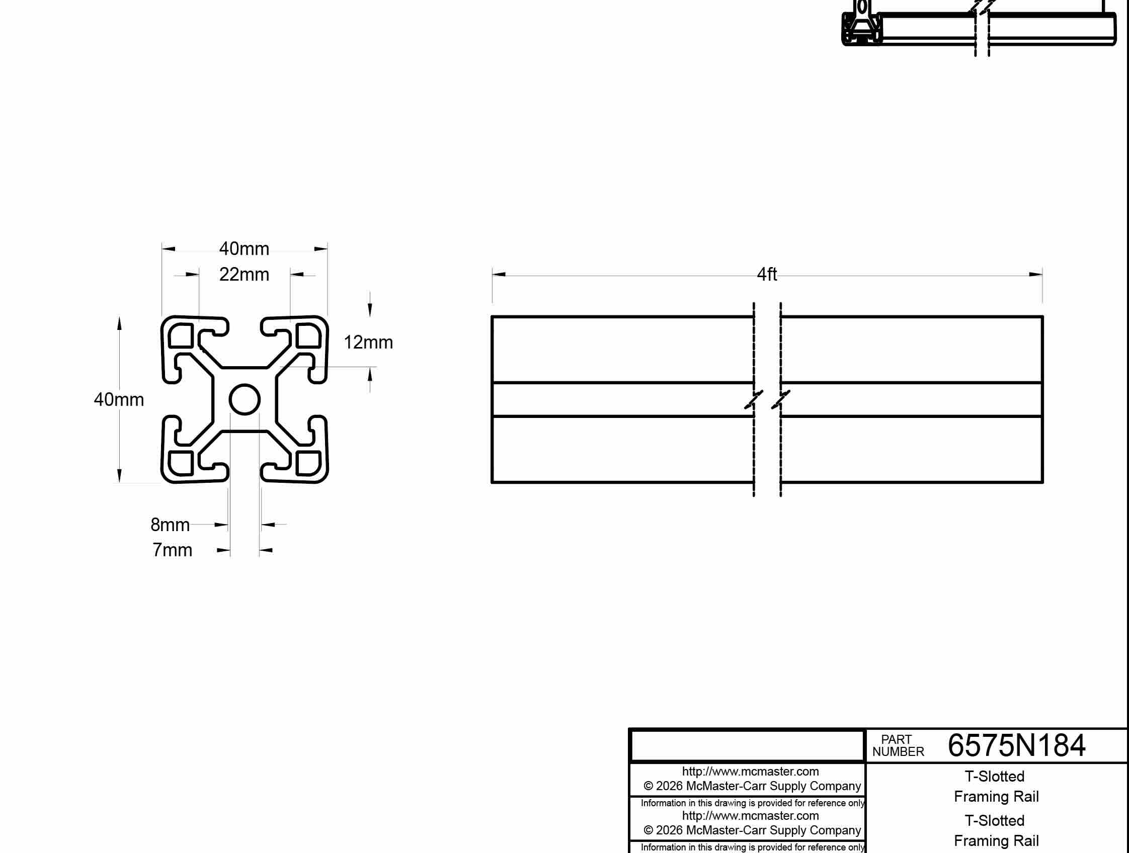
I plan to use T-slot extrusion as a part of this base.
Parts forthcoming
In addition, I will fabricate components used to secure the t-slot to a wall. These parts will be cut using a water jet, use a die/tap to thread the parts, and then secured using 3M bolts. i will design and create these parts during wildcard week.
T-Slot Fastner- to be used with M3 screws. I water jet cut them and then used a tap to put threads in the piece.
This part was based on the dimensions of the T-slot extrusion sourced for this project:
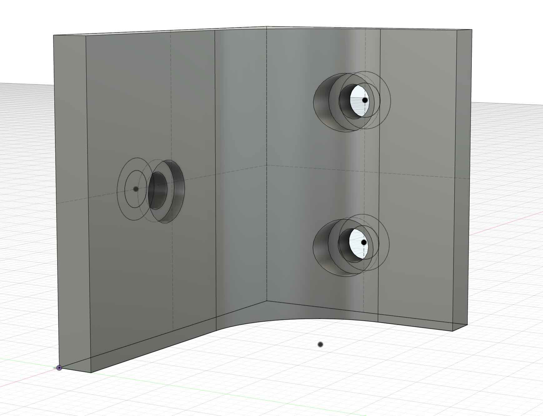
Enclosure
I created an enclosure to hold the MCU, the TOF sensor, and minimp3 player, and speaker. It is to be mounted at the bottom of the base and allow for power in and then power and data lines to run to the NeoPixel strands. The enclosure will use brass heat inserts and m3 bolts to secure the lid to the enclosure and the enclosure to the base.
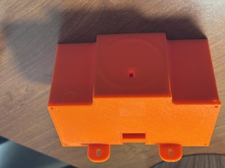
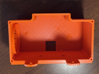
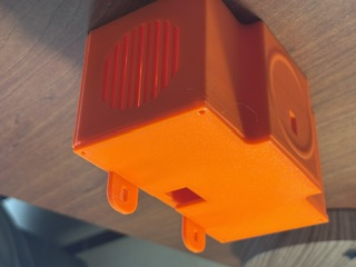
File- 3mf of enclosure and lid
Wiring and Wiring Management
As part of wiring management, I have to determine what is the most effective way to connect the power of the 16 different strips. It must be safe, modular, easy to fabricate, and easy to install. Ideally, it should also be relatively inexpensive.
The exhibit will require data line and power running to the LEDs and power to the mini-mp3 player and Jeffuino. I created a wire holder that will hold wires to the top and bottom of the base. The holder is designed to snap fit on a hole cut in the base.
The gauge of the wire should be 12AWG to count for the current and wattage of the exhibit.
NeoPixels
The exhibit will be comprised of 16 meters (48 feet) of LEDs total, at 60 NeoPixels per meter = 960 NeoPixels total.
specs quoted from https://cdn-shop.adafruit.com/product-files/1461/SKC6812RV__12VOP0274E_REV.A1_EN+PID+1461.pdf and https://www.adafruit.com/product/1461
- 60 RGB LEDs per meter
- 12.5mm (0.5") wide, 4mm (0.16") thick with casing on, 16.7mm (0.65") long per segment
- set the color of each LED's red, green and blue component with 8-bit PWM precision
- 24-bit color per pixel
- LEDs are controlled by shift-registers that are chained up down the strip so you can shorten or lengthen the strip.
- Only 1 digital output pin are required to send data down.
- PWM is built into each LED-chip so once you set the color you can stop talking to the strip and it will continue to PWM all the LEDs for you.
- SKC6812RV Resistance to Soldering Heat Tsld = 260°C, 10sec. 2 times
power usage
- over a certain distance - 18 Watts max (~3.5 Amps @ 5V) per meter instead of 9.6 Watts max (~2 Amps @ 5V). usually the actual current for colorful design is about 1/3 to 1/2 the max current. A good power supply such as our 5V 10A supply is key!
- Maximum 5V @ 60mA draw per 0.65" strip segment (all LEDs on full brightness)
- 5VDC power requirement (do not exceed 6VDC) - no polarity protection
- Note- heat dissipation is important- service life of the light source is 25 ℃, the service life of the product is 50000h (Note: theproduct is under the condition of good heat dissipation
Timing-
- The protocol used is timing-specific and can only be controlled by microcontrollers with highly repeatable 100nS timing precision. We have example code for using with the Arduino Uno/Mega microcontroller at 8MHz and 16MHz
RAM
- the entire strip must be buffered in memory
- 1500 bytes of RAM is approximately enough for about 500 LED pixels.
Conclusions
Because each NeoPixel segment can draw up to 60 mA at full brightness, with 960 LEDs total (16 meters, 60 LEDs per meter), the total ampage required for the project, theoretically, wuold be a maximum of about 57.6 A at 5V if all NeoPixels are fully lit white.
The Xiao ESP32C3 should be able to handle the Timing and RAM of the neopixels. The XIAO can opersate at 160 MHz and has 400KB SRAM and 4MB Flash, plus it can use wifi as well as I2C (to connect/read the TOF sensor).
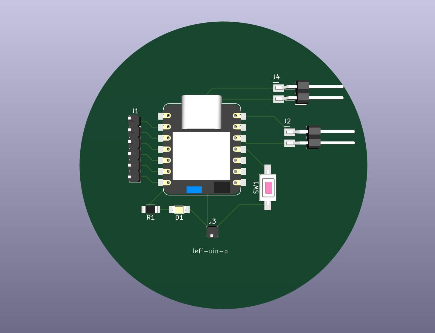
Controller board
I will be using the Jeffuino board for this project, only using an ESP32C3 rather than the RP2040 I had originally intended to use. The footprints and pinouts are the same, although the specs for the boards are different.
FileImage of Board
Reviewed
Adafruit Learning System. “Adafruit NeoPixel Überguide.” Accessed June 15, 2022. https://learn.adafruit.com/adafruit-neopixel-uberguide/the-magic-of-neopixels.
Bill of Materials (BOM)
| Component | Quantity | Supplier | URL | Price |
|---|---|---|---|---|
| Exhibit | ||||
| Acrylic (Clear) 12” x 24” x 1/8” | 32 | MakerStock | link | $8.50 |
| Backing/Mount Structure | ||||
| Plywood ¼ in | ||||
| T-Slotted Framing Rail, Single Four Slot Rail, Silver, 40 mm Square, 4 Feet Long | 4 | McMaster Carr | link | 40.22 |
| M3 screws | ||||
| T-slot nuts | ||||
| Means to fasten to wall | ||||
| Braces/PETG | ||||
| NeoPixel addressable LEDs | ||||
| Adafruit NeoPixel Digital RGB LED Strip - Black 60 LED 4m | 4 | Adafruit | link | 54.95 |
| Female DC Power adapter - 2.1mm jack to screw terminal block | 4 | Adafruit | link | $2.00 |
| 2-pin JST SM Plug + Receptacle Cable Set | 15 | Adafruit | link | $0.75 |
| Enclosure | ||||
| PETG | ||||
| User Input sensors | ||||
| VL53L5CX Time-of-Flight 8×8-Zone Distance Sensor Carrier with Voltage Regulator, 400cm Max | 1 | Pololu | link | 19.95 |
| MCU/Processing | ||||
| XIAO ESP32C3 | 1 | digikey | link | 4.99 |
| Sound | ||||
| DFPLAYER - A MINI MP3 PLAYER DFR0299 | 1 | digikey | link | 5.9 |
| 36mm Speaker w/ Wires - 8 Ohm 2 Watt | 1 | Adafruit | link | $1.95 |
| Power | ||||
| 5V 20A switching power supply | 4 | Adafruit | link | $29.95 |