Week 07 Computer Controlled Cutting
This week's tasks were
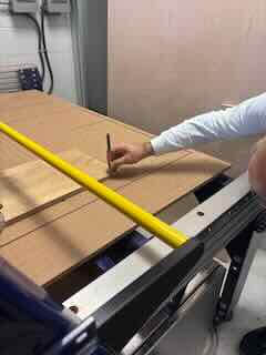
group assignment
- do your lab's safety training
- test runout, alignment, fixturing, speeds, feeds, materials,and toolpaths for your machine
individual assignment
- make (design+mill+assemble) something big (~meter-scale)
- extra credit: don't use fasteners or glue
- extra credit: include curved surfaces
- extra credit: use three-axis toolpaths
Project
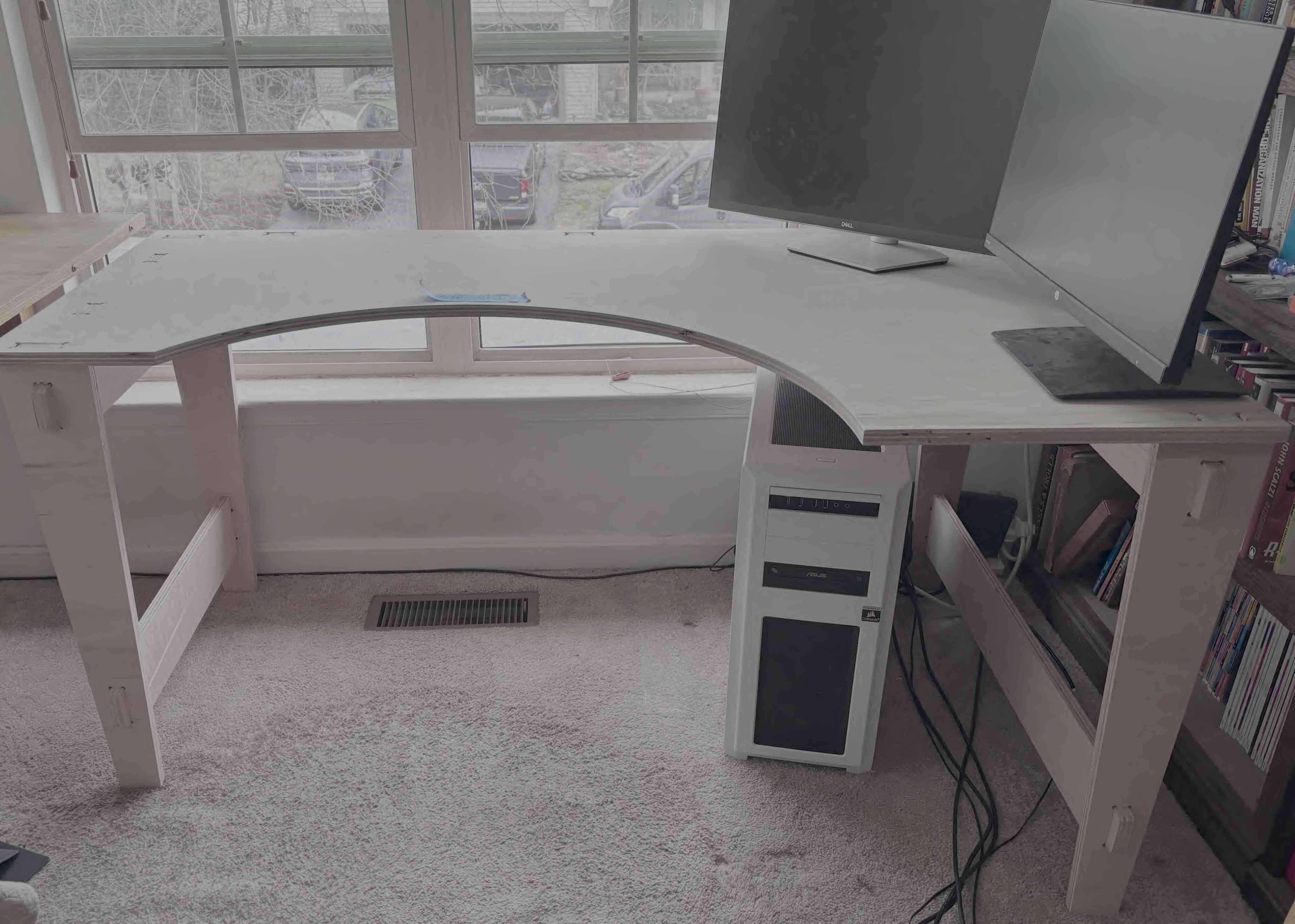
I created a desk personalized to me and my workspace...and my car (which I had to use to transport the parts).
This is the first time I get to work in my node- the UNC Charlotte Super Fab Lab. It was an eight hour drive to get there.
Group project
I worked on this on my own as all of the students in this node are remote. I went through the safety training and test run of the CNC. For the cuts, we would use the default speeds and settings for thickness of the material. I was advised that you always had to wear eye protection, no loose clothes or hair. The space for the shop bot is pretty constrained and kicks up a lot of dust. It is good to have it enclosed from other equipment.
Overview of the Shopbot PRSAlpha 96-60 CNC machine
5 x 8 cutting surface
In X, Y and Z- the Z is up
The shopbot is controlled by both software and physical switches.
The two chief software applications used are:
- Shopbot CNC
- VCarve Pro
For the CNC to work properly, you have to have precise measurements of the material/stock being used.
You would need to set these dimensions in the VCarve software.
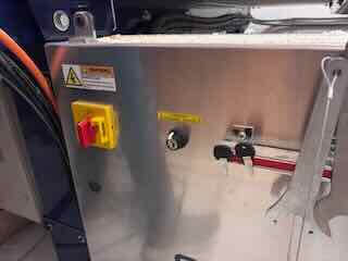
The machine also has the following switches that turn on the system (note the keys that go with turning on/engaging the spindle- this serves as a two step operation to ensure against injury).
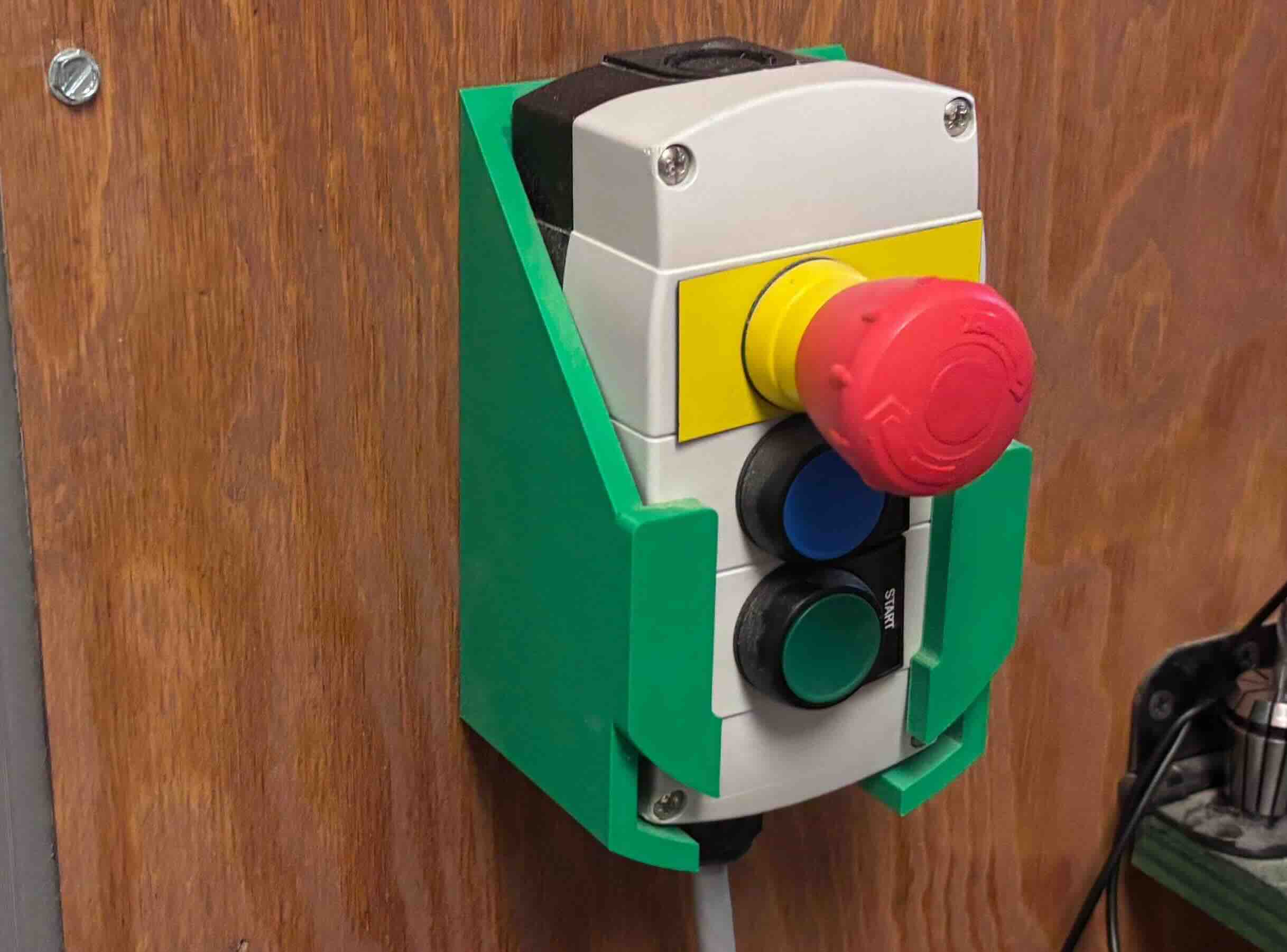
The Remote pendant has three buttons
Emergency stop - Red
Reset - Blue
Start - Green
When you use the shop bot, you need to turn on the dust removal/vacuum compressor before you start cutting.
In order to cut, you need a sacrificial layer, a piece of mdf that covers the workspace, to allow the CNC to cut through the material without damaging the bit on the metal of the machine.
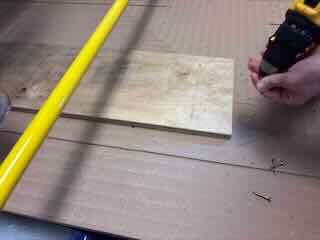
For safety and to ensure the material doesn't shift and ruin the cut, the material/stock needs to be secured to the sacrificial layer. There are a number of ways to do this, but I was instructed to use a power screwdriver and screws to screw the material to the sacrificial layer. For a larger piece- 4 by 8 feet, six screws would be needed.
To work effectively, the machine needs to have the origin (the location of 0,0,0) defined for it. When it cuts on the x, y and z planes, it will do so based on how the design relates to this origin. To ensure that the CNC cuts effectively, we will need to zero the axes.
Zero the axes (the plural of axis, and I suppose of axe)
To zero the x and y,
move the spindle to a point on the material/cutter that is at the edge of the material. As the screws can damage the bit, it is important to account for them in the placement of the parts and in zeroing the axes of the machine. I gave the machine an inch in from the screws- which 32 square inches of material lost as a result. I know that it is a subtractive process, but there is a lot of waste.
To zero the z axis
Remove the dust foot before you start.
The Shopbot has a built in process to zero the z. It uses a clamp that makes the mill bit act like a capacitive sensor. It is simiialr to using a continuity checker on a multimeter. You place a metallic plate under the bit and the machine will lower the bit until it touches the metal plate. I pressed the z zero button on the software, and used the metal plate
Place the Clip on to the collet. Press the metal plate beneath the bit. Press the zero zaxis button. The machine automatically zeroes the z axis.
The spindle speed for cutting is 18000 rpm. the feed rate that seems to be the default is 3 inches a second on the xy plane,
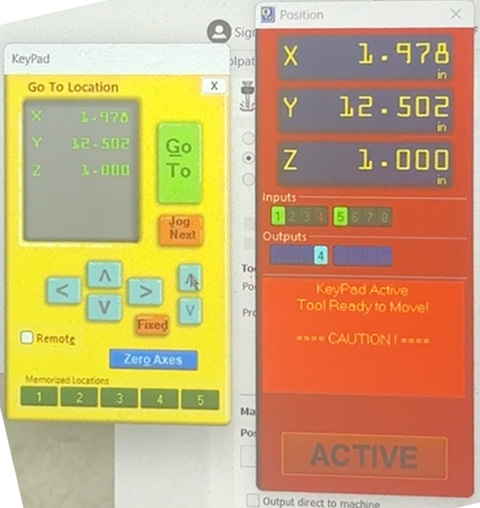
You can manually control the xy and z movement of the spindle by using what is called the "gameboy":
The following steps define the workflow of using the Shopbot PRSAlpha 96-60 CNC for a cut using a single bit.
- Measure and Secure material
- Install bit
- Create/prepare toolpaths (using VCarve)
- Save toolpath
- Turn on CNC and zero X and Y
- Zero Z with plate
- Load and start the job
- Turn on spindle and dust collector
- Monitor cut
- Remove part
I created a transcript of the safety overview and training using the transcription app otter.ai and I took a lot of photos. Afterwards, to create a detailed summary of what had been presented I copied and pasted the transcript into chatgpt 5.2 and used the following prompt. My goal was to create an easy to use check list for when I worked on my own.
based on JUST this text and these photos, create an instruction manual of how to use the shop bot. drawing from photos I provide, Insert images where they are appropriate or needed. Create a basic outline that I can use to remind me of the steps I need to take to run the CNC.
It provided a result, which I edited. The prompt did not include images, as I had asked. Below is the edited version of this check list.
ShopBot CNC Operation — Step-by-Step Checklist
1. Measure and Secure Material to the CNC Bed
- Place material on sacrificial layer
- Measure the length, width and thickness of. the material.
- Align board with machine reference marks
- Align board with machine reference marks
- Fasten with screws (typically corners)
- Ensure screws are outside toolpath area
- Add additional screw if board is warped
2. Install the Cutting Bit
- Verify spindle is off
- Loosen collet nut (left = loosen)
- Insert bit (in this instance, I used a ¼-inch flat end mill)
- Leave a small portion of shank visible
- Tighten collet (right = tighten)
- Confirm bit is secure
3. Prepare Toolpaths in VCarve Pro
- Open VCarve Pro
- Select New Job
- Units = Inches
- Zero position = Machine Bed
- Enter stock width and height
- Enter stock thickness
- Import DXF or SVG or draw geometry
- Position design on board layout
- Create toolpaths (in my case, I used Create Pocket and Profile Toolpaths)
- Set Tool (in my case, a ¼-inch end mill)
- Set cut depth and passes (machine usually automates this but you need to check it)
- Press the Calculate toolpath button
- Select the Profile Toolpath button
- Select Outside cut (in this instance)
- Add tabs for support (so the part is stable)
- Set final depth slightly deeper than material
- Press Calculate toolpath button
4. Save the Toolpath
- Click Save Toolpath
- Ensure desired toolpaths are checked
- Machine: PRS Alpha 60
- Post processor: ShopBot Inch
- Save file
5. Turn on Machine and Set the X–Y Origin (Work Zero)
- Open pendant control (Game Boy)
- Use arrow keys to jog spindle
- Move spindle to lower-left corner of workpiece
- Ensure bit is clear of attachment screws
- Click Zero Axes
- Zero X and Y
6. Set Z Zero (Touch Plate)
- Place touch plate under the bit
- Attach clip to spindle
- Select Zero Z Routine
- Confirm prompt
- Machine lowers until bit touches plate; machine double-checks
- Machine raises up when finished
- Remove plate and clip
- Store plate securely
7. Load and Start the Job
- Close pendant control
- Click Cut Part
- Open previously saved toolpath file
- Ignore dialog that tells you the material will be cut all the way through
- Click Start dialog button in software
8. Start Spindle and Dust Collection
- Insert spindle key
- Turn key to the right to activate spindle
- Turn on dust collector
- Press green Start button on remote pendant
9. Monitor the Cut
- Watch first tool movement carefully
- Keep hand near emergency stop (E-stop) button
- Use E-stop if necessary
- Verify toolpath runs as expected
10. Remove the Finished Part
- Wait until spindle stops
- Remove screws from sacrificial layer
- Cut or chisel tabs
- Lift material
- Post-process/sand part and tab locations if needed
Project
Initially, I had wanted to work on two projects- I wanted to cut the struts/supports for my final project and I want to build a desk to replace the cobbled together desk I have in my office.
As I began to work through ideas for the struts, I realixed that the geometry of rectangular struts could present problems in designing and fabricating them on the CNC. This would likely complicate the design and fabrication of the geodesic dome itself as well as the design and fabrication hubs that would connect and hold the struts. In addition, the size of the project presents problems for where I will place it and how users would enter it. As I have a number of questions that I need to answer before I can begin fabricating the struts, I decided on two things.
Consequently, I have a few tasks that I need to complete.
research the viability and feasibility of using PVC tubing for the struts rather than cutting them from plywood. Would they be of adequate strength for this roject? How easily can they be cut and attached to the hubs?
Setermine the viability and feasibility of the design in terms of the context in which it will be located. I have concerns that my initial idea will not work due to space considerations. I need to better understand its size relative to the space and how I can design the experience to best accommodate the space. This might require changing the scope or concept of the work.
Research and work through the project in order to get a better understanding of how users would enter/move through it/engage with it and any ADA requriements that might need to be accommodated. Some of these questions will be answered during the input and output weeks, but how they use it will shape the design.
I decided that I was not ready to cut the struts.
The second project was the desk. I sketched multiple concepts until I hit upon an idea that I liked and that fit the space and materials.
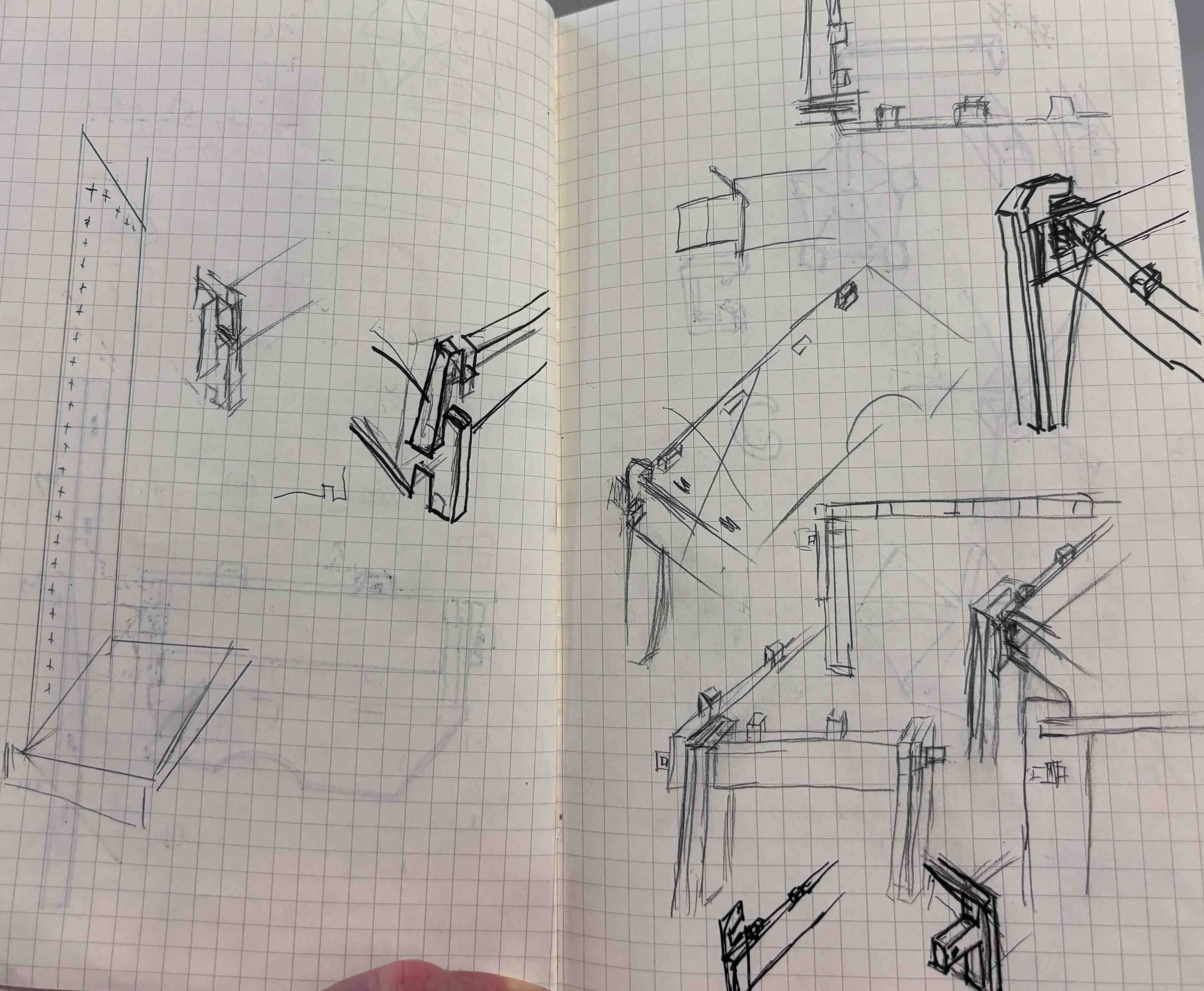
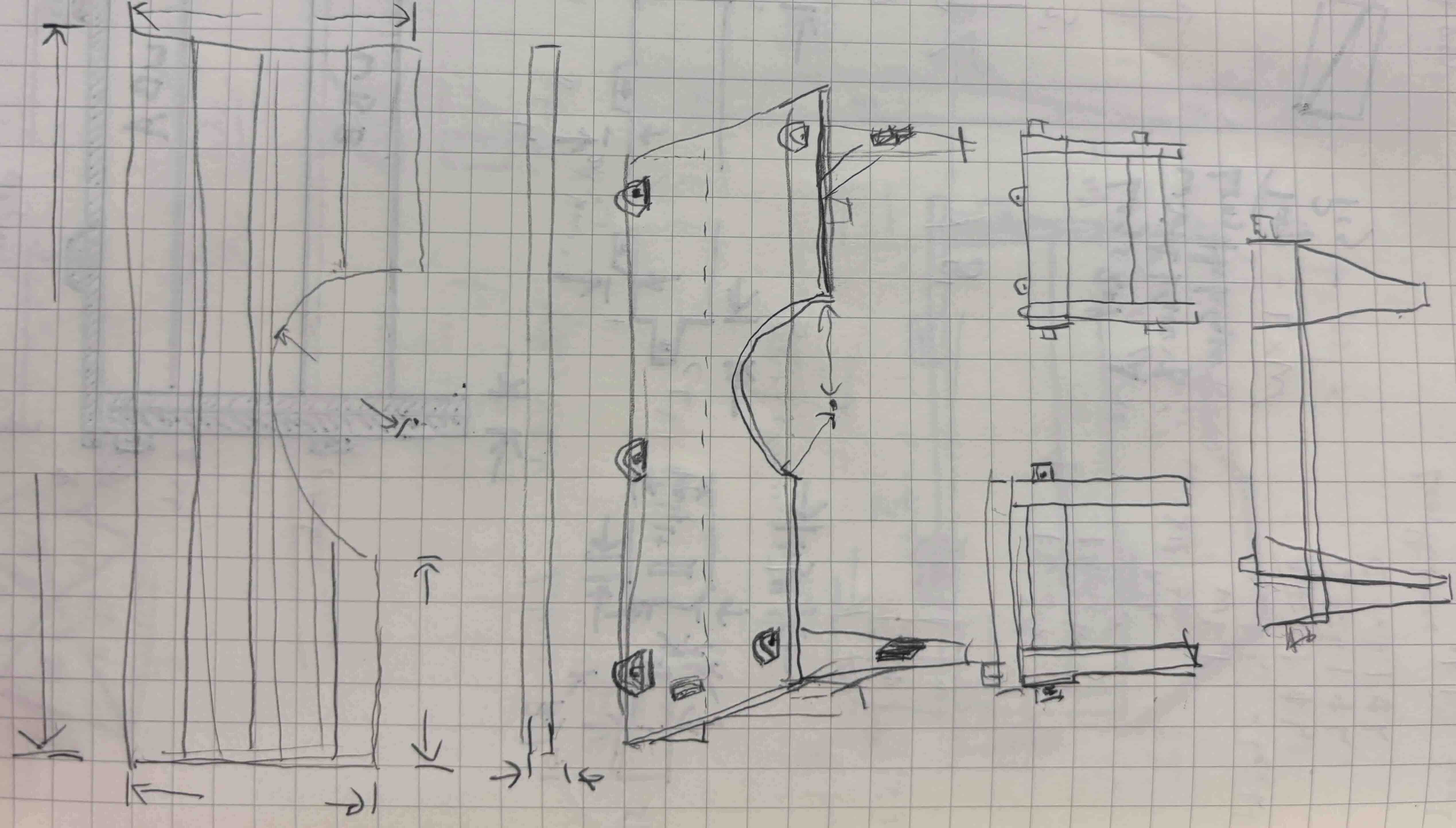
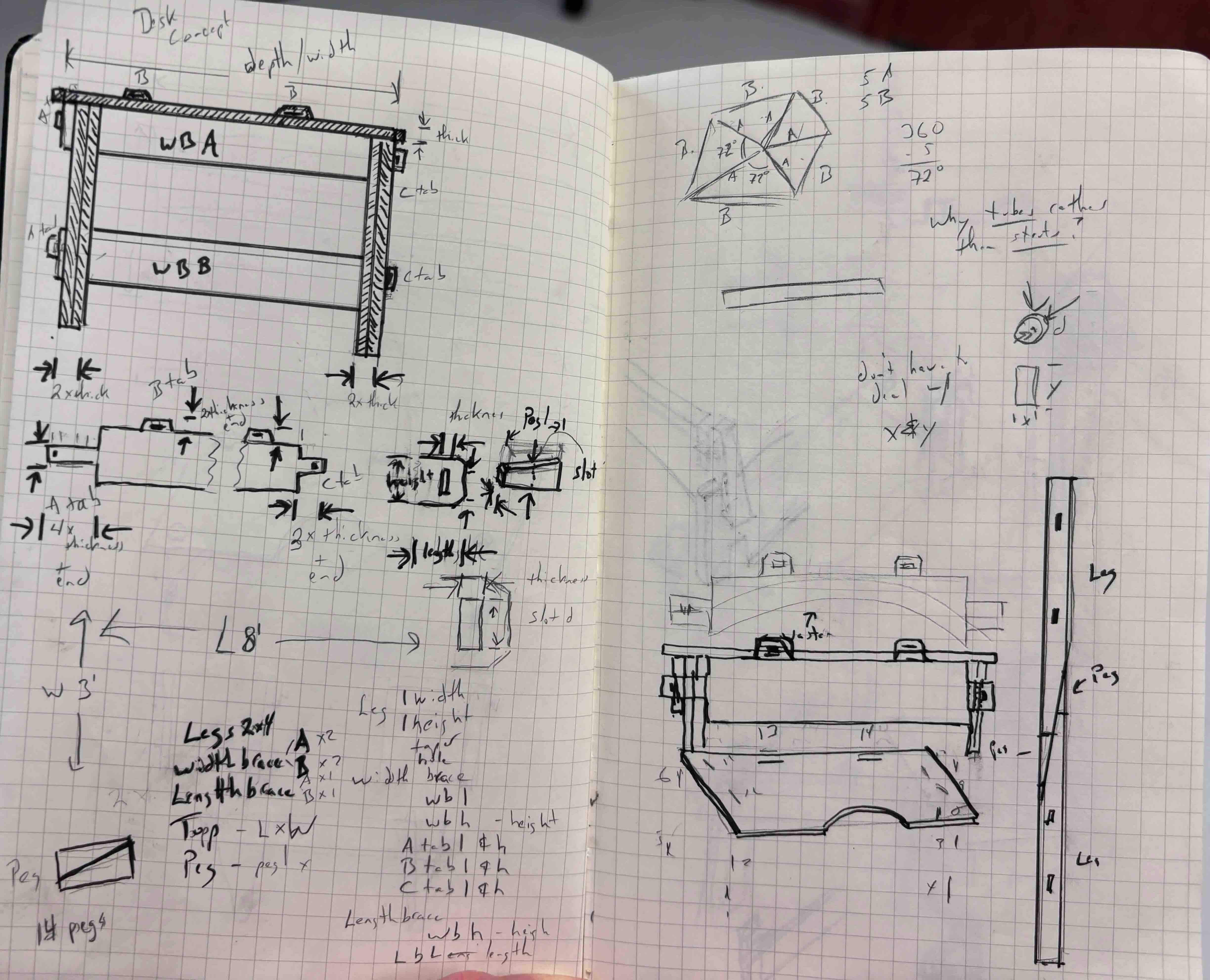
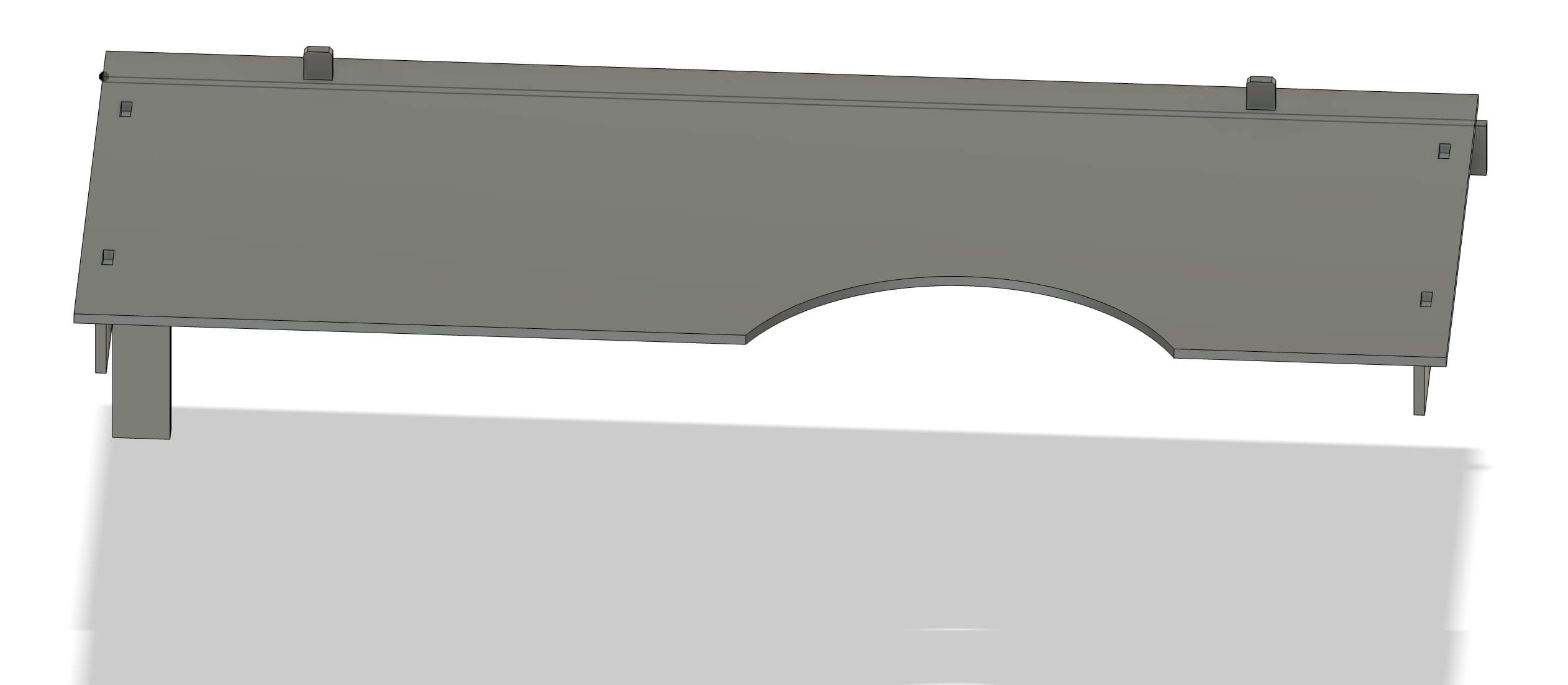
I then began measuring my existing space. I initially wanted to have an eight-foot-long desk, with room for a number of different workspaces and storage. The desk would have a curve in it so that I can have more workspace within arm's reach. It would be assembled without any fasteners. Okay, this could be really nice. Because I would only have a limited amount of time to use the CNC, I wanted to make sure that my design was ready to go. Consequently, I started to design the concept in fusion. I decided upon this design.
Before I left, I measured the interior of my car. Because I have to drive to the lab, I needed a design whose components would be sized to be transported by my car. The distance would preclude tying it to the roof and I realized that the largest I can fit into my trunk is 5 foot by three foot. I need to rethink my design.
Lessons learned- Identify the constraints under which your design needs to operate. In this instance, material constraints, context of use constraints (where I will install it, how I would interact with/use it, and logistical constraints (moving the materials and final components).
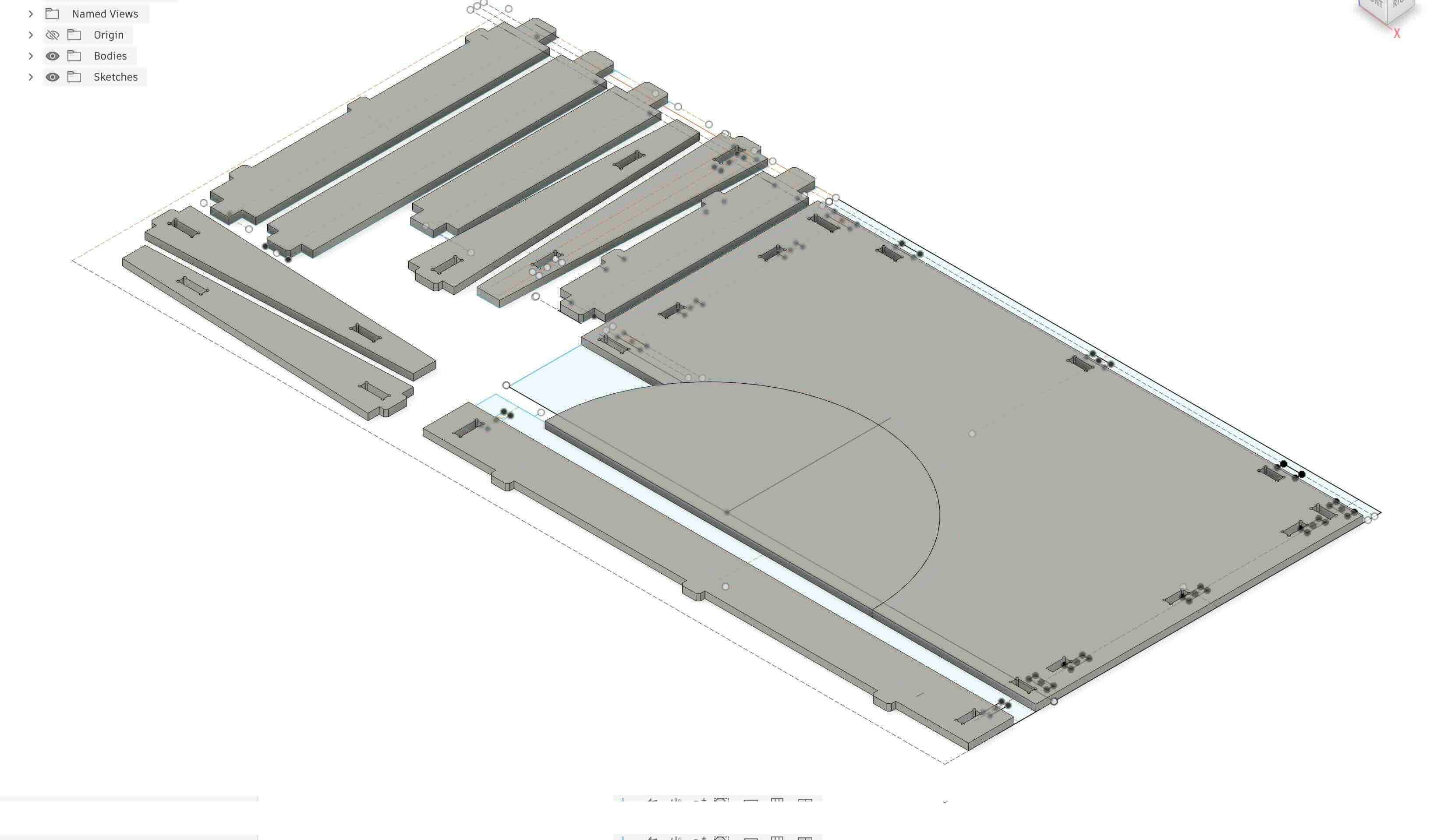
Computer Aided Design
I started over in Fusion, where I began laying out my design on a 4x8 foot plane to get an idea of how much I could build on one 4x8 foot sheet of plywood. I drew this as a sketch because I assumed that this would needed for the CNC. I have a little experience with CAD, but I am not as proficient as I would like. The choice to design it first in 2D was purposeful- material dimensions are a constraint that my design must accommodate, but the downsize is that I cannot see how the parts fit together. To remedy this problem, the sketch was laid out using construction lines so that I could see how the parts would align. In addition, I sketched out freehand how the parts would fit. It was not as ideal a solution as 3d rendering the project would have been, but for the purpose of this project it worked.
When I arrived, I purchased two 4x8 foot sections of 3/4 inch plywood. I had to strap them to the roof of my car to get them to the lab (I neglected to take a photo of this, but if you are familiar with the Beverly Hillbillies, my car looked like that). Mental note- logistics matters in making stuff.
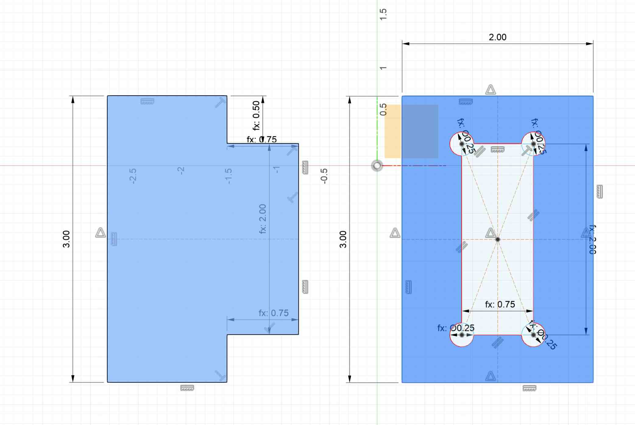
In seeing the lab and examples of some of the work the CNC could create, I realized that I would need to revise my design again. The CNC can't do perfect 90 degree angles. I had seen a design as an example of a press fit joint in the lab and thought it would be effective for my project. I developed a simple version of it to test to see if it would work.
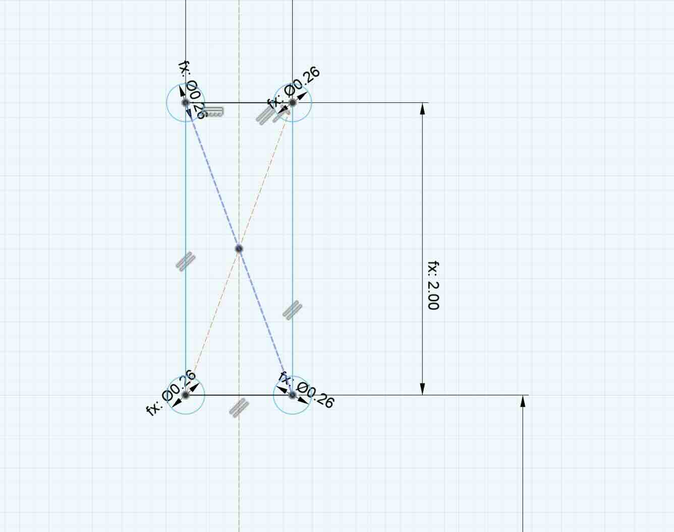
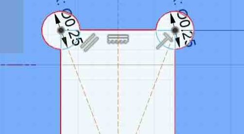
The circles in the corners -or dog bones- are meant to address the constraints of the bit (0.25"), which would not be able to create a 90 degree angle on an interior cut. For exterior cuts, the CNC could overshoot, but for interior cuts there's nowhere to overshoot -unless you add the circle at the corner of the angle. By knocking out the circle (whose diameter is the diameter of the bit + .01"), the joint can accommodate the 90-degree angles it was designed to hold.
I realized, when I looked at the sketch, that I had not chamfered the ends of the tabs that would be inserted into slots like this. I knew better but had forgotten. Good to catch it now. I chamfered the ends.
Lesson learned- work through concepts before you execute so that you don’t waste time and material. Even better, have a fresh set of eyes look at your design.
I tried to save as DXF (Drawing Exchange/Interchange Format file) and import into VCarve, but this didn’t work as VCarve showed ALL of the lines – lines from the extruded objects, the construction lines, the lines of the sketch. Everything.
This was a problem
I changed to using the Shaper Origin export utility I had installed in a previous class, and exported the sketch faces as SVGs. That really didn’t work well. When I opened the file in Inkscape, the design didn't match the chamfered project I'd built. The dimensions and the scale were off.
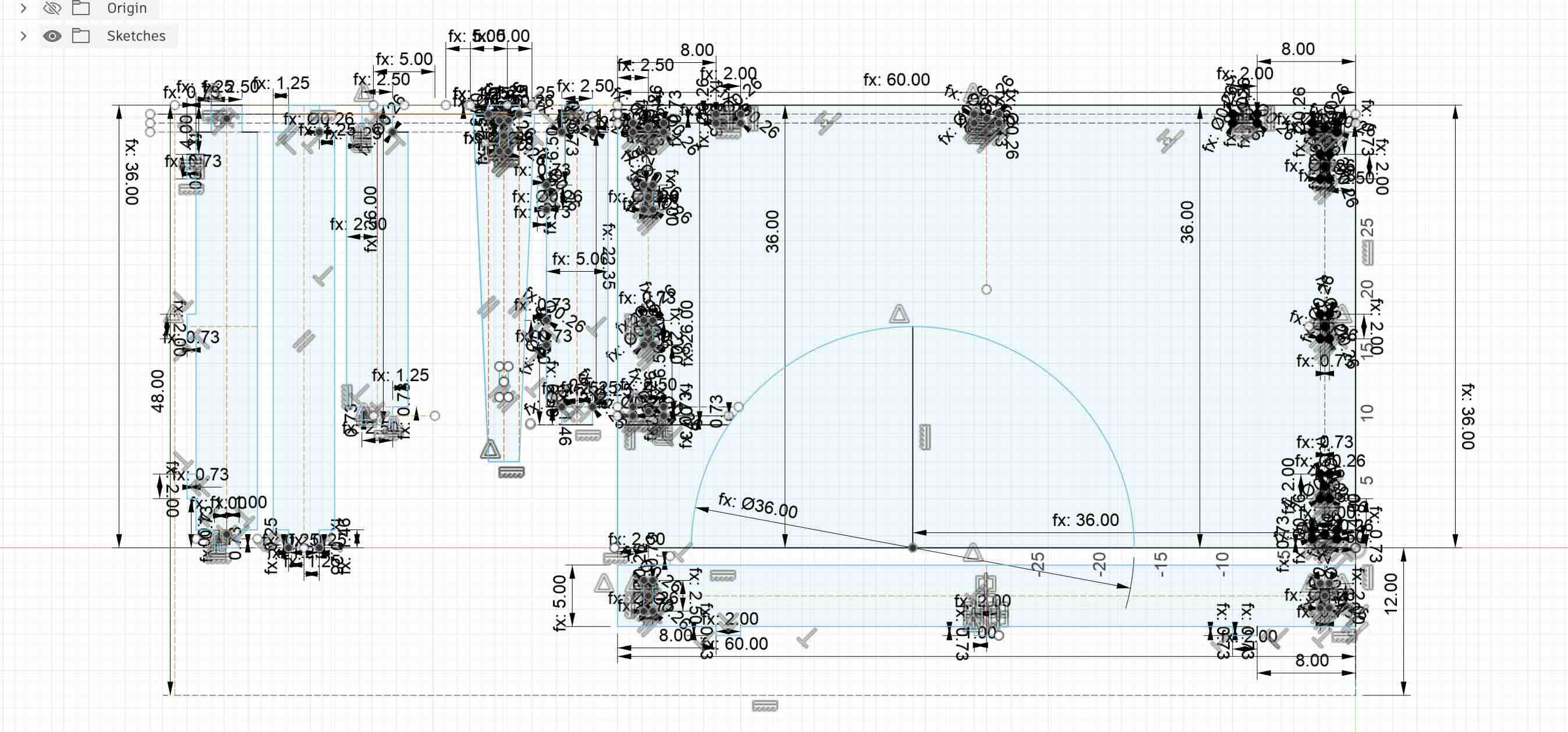
Solution- I decided that I would need to clean up the sketches and just export the lines- without any other element on the screen. I rolled the design back to the sketch step, removed all construction lines and removed any extrusions- just the sketch. I exported that as a dxf. This was not ideal, as without the construction lines the design, free of constraints, would change in unexpected ways – such as no longer having perpendicular angles or the dimensions would change. As a solution, it created more problems – such as it made it difficult to make revisions to the existing file without putting all of those lines back in- but this was the best means to actually cut the parts. I exported as a DXF,
To effectively print this, I also needed to remove some of the lines in the dog bones to accommodate the CNC cutting on the outside. Any interal lines would create problems as the CNC would try to cut outside of them.
Dogbones with lines
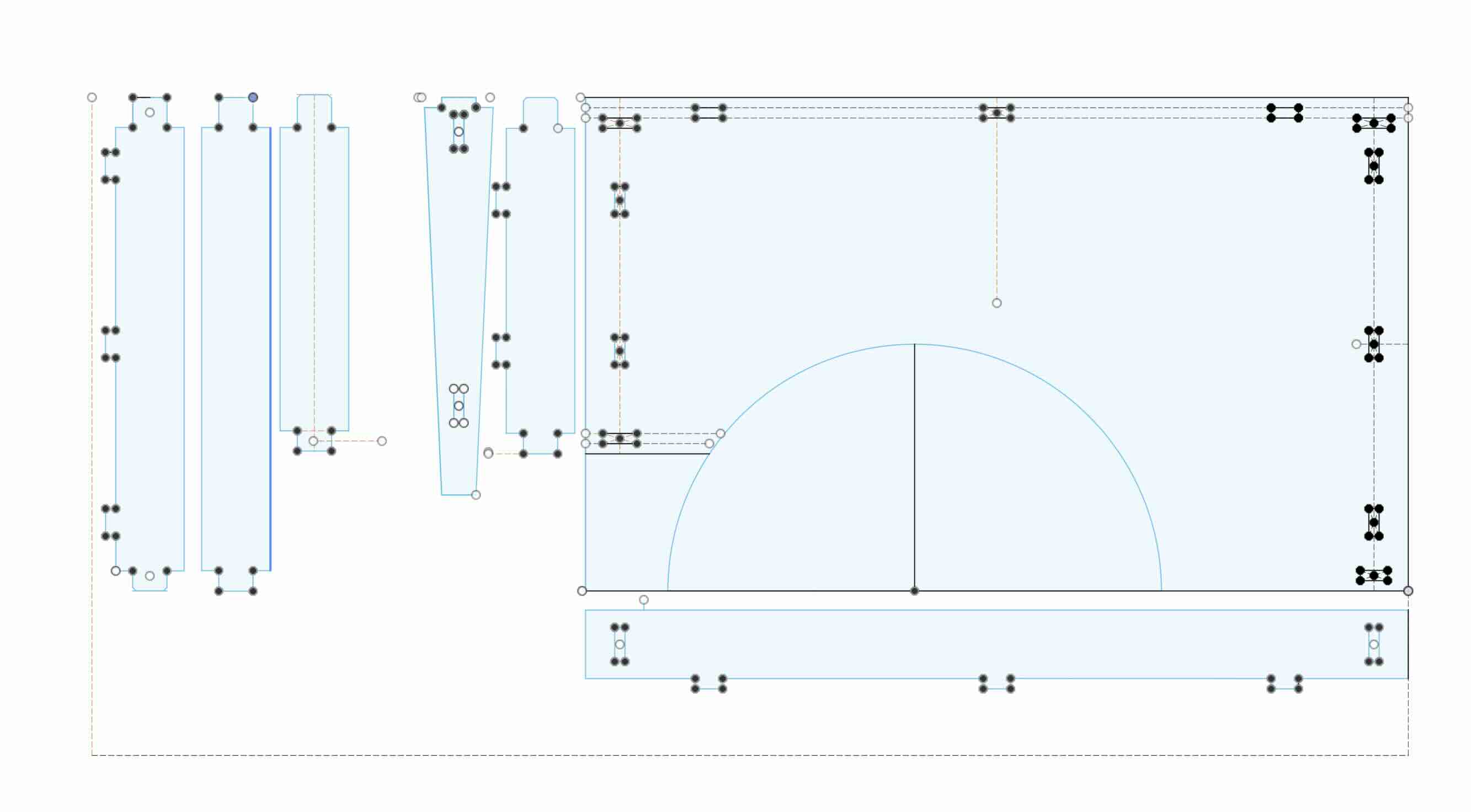
To get the CNC to accurately cut this dog bone, you have to remove the internal lines by using the scissors button in the design section of VCarve.
So I've removed the lines and am ready for the test cut.
Test cut fil
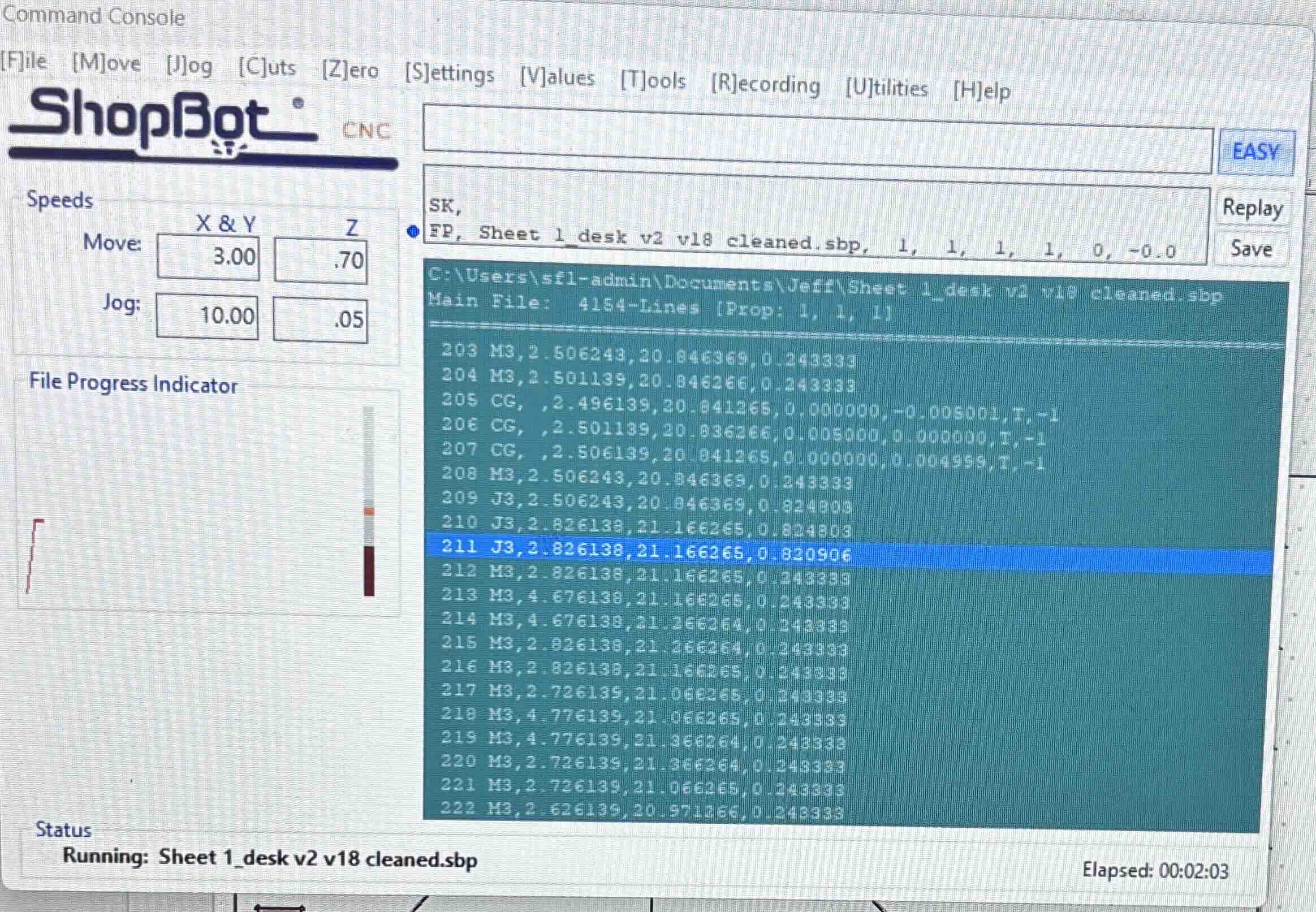
I would select the vectors and then set the toolpaths for each. You can save multiple toolpaths. When you are ready to cut, save the toolpaths in VCarve and then open it in the shopbot software. The shopbot software reads the gocode and operates the CNC.
Success! (note- I do not as a rule, use exclamation points willy nilly. This one is called for.)
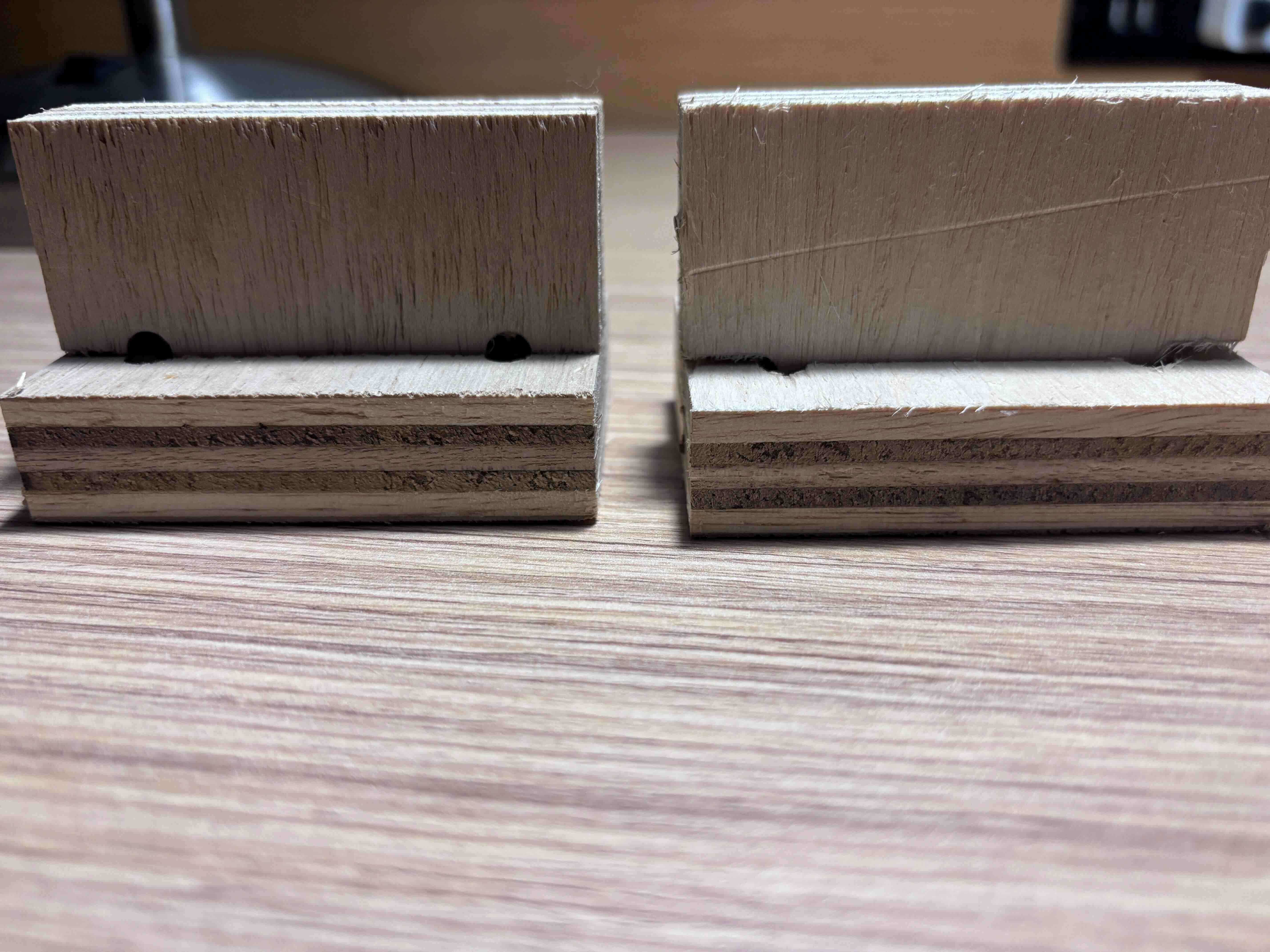
It was pointed out that I needed to add dog bones on both the 90 degree angles of the tab and in the slot. I revised the file and reprinted. Perfect fit.
Test cut double dog bone.
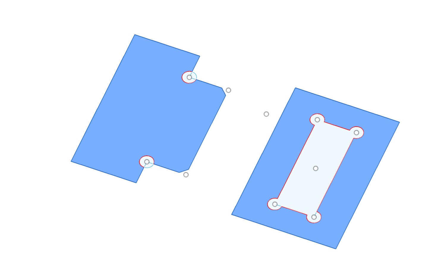
Results- the double dog bone is on the left, the initial test is on the right.
Going forward, I decided to think about how I can test my design in increments to ensure that what is fabricated functions as anticipated with the smallest waste of time and materials. The test cuts taught me that I will make mistakes and to catch them requires that I work through these steps and analyze each result. After the test joint, I think I'll print the desk top first, and then individual parts to test that they fit as expected. This way, I could measure the desktop to ensure that it fits the design's dimensions and then test each part so as to not waste material or time.
In working with the VCarve software, the software wouldn’t read the svgs. The dxfs would work, but I would have to go back in and manually change all of the elements.
In addition, for some reason the vectors were not being recognized as vectors in the software. I would have to use the join function in VCarve.
The process to move the files from fusion to vcarve was laborious and time intensive. I would have to revise in fusion, then remove the construction lines, import into vcarve, and edit/touch up the sketches. Many of the sketch elements didn’t come across as vectors and vcarve treated them as open. I had to close them- which I assume means that the individual lines needed to be connected to allow for uniform toolpaths. Without these connections, the CNC could cut it, but would jump around. I am not sure whether the vectors being considered unconnected in VCarve was the case. I suspect, but am still unsure, that the minimum width of stroke in the sketches being exported might be an issue. I was using a 1 pixel width, but perhaps I needed to use a percentage of an inch instead.
In addition, I would need to use the cut function in VCarve to remove any construction lines in the design.
I worked through the files for my project, first printing the desktop, then the brace for the length, then the brace for the long width, the short width, the bottom braces, and then the legs.
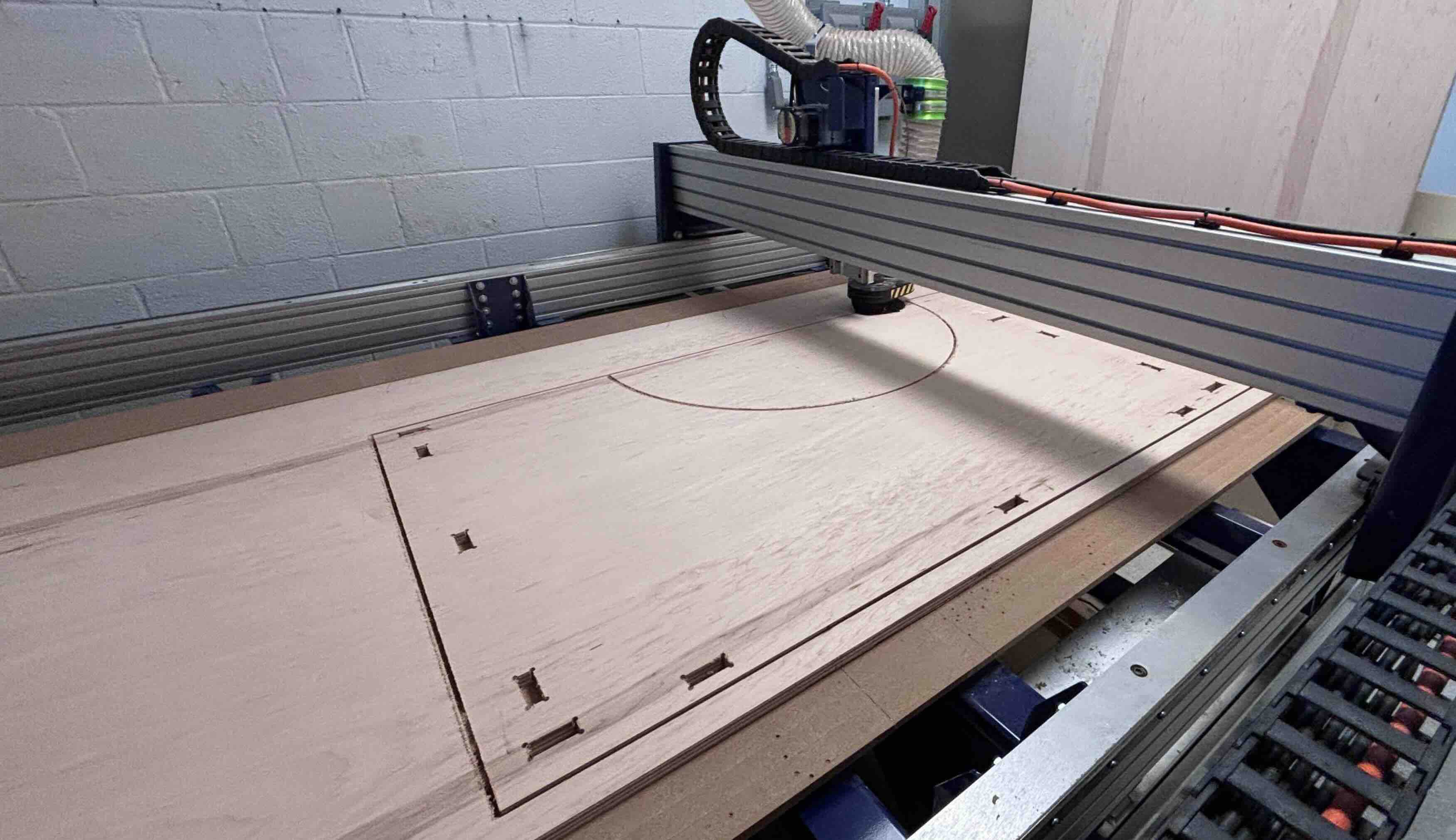
I had two problems. One, every now and then the toolpath of the CNC was supposed to retract and move to another spot without cutting the material, but would instead not retract high enough and move across the piece, cutting the material as it moved. I believe that has something to do with warping of the material or the thickness of the material or the gcode.
The second problem was that I had neglected to remove all of the construction lines, which caused the CNC to think that it needed to cut outside of ALL of the construction lines as well. If a construction line is hidden by a line in the sketch that obscures the construction line, I don't see it to remove it, but VCarve sees it and sees it as two seperate lines. As a result, becasuse the CNC is set to cut on the outside of external lines, the outside of these "invisible" lines would often cause the CNC to actually cut inside the piece being cut.
CNC inside fail
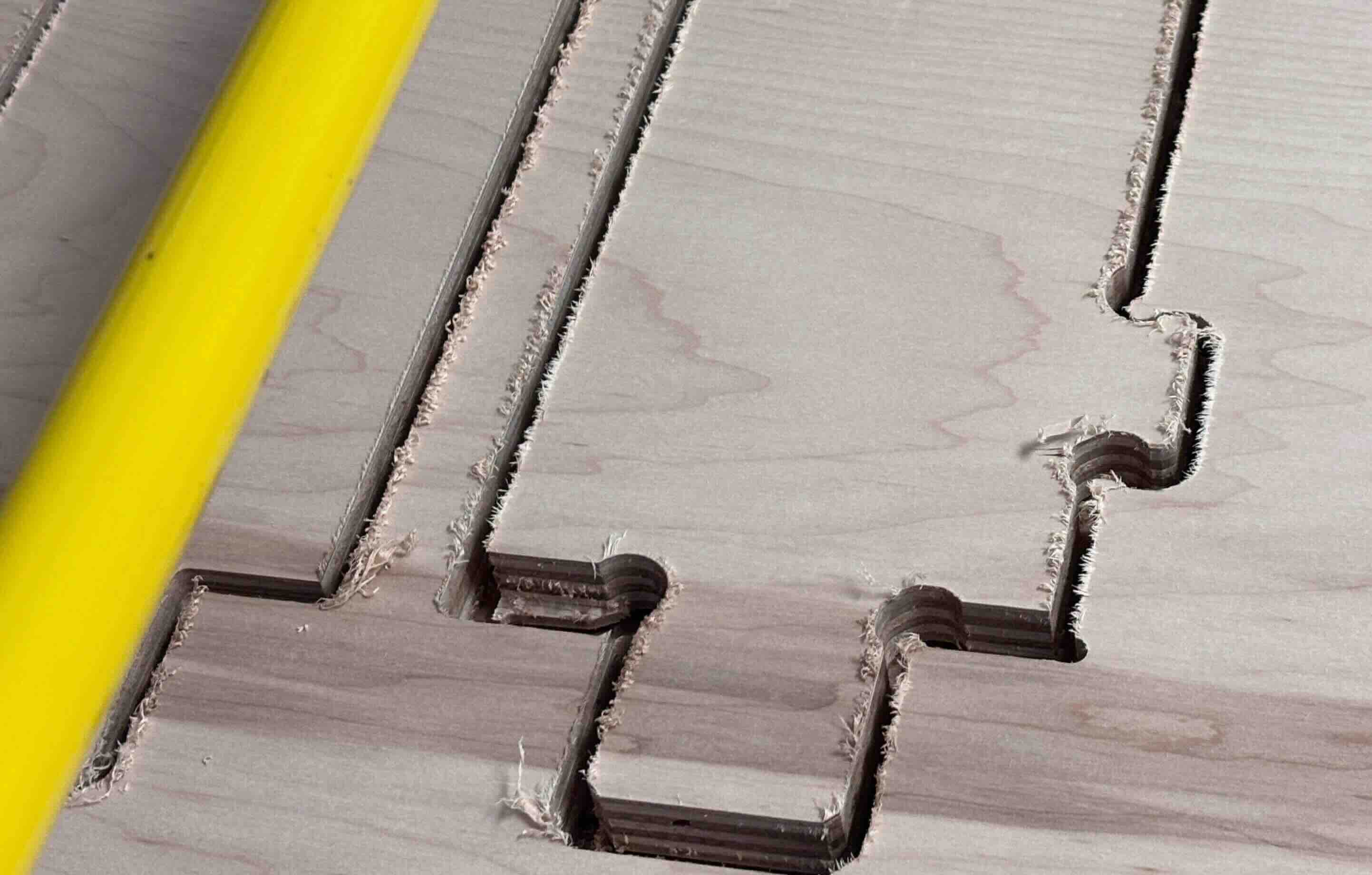
This was a pain in that to solve this problem I would need to select lines- use the arrow keys to move the line up two or three pixels, delete the line below them, and then reselect and move the lines back down the same number of pixels. That was a pain to do.
I went back, cleaned up the file, made sure that all of the construction lines were removed, and printed the remaining parts.
The Charlotte Super Fab Lab is not open on weekends and I had a deadline of Friday night to complete the cutting. I loaded the cut parts into my car, listened to audio books for eight hours on the drive back, and then started post-processing.
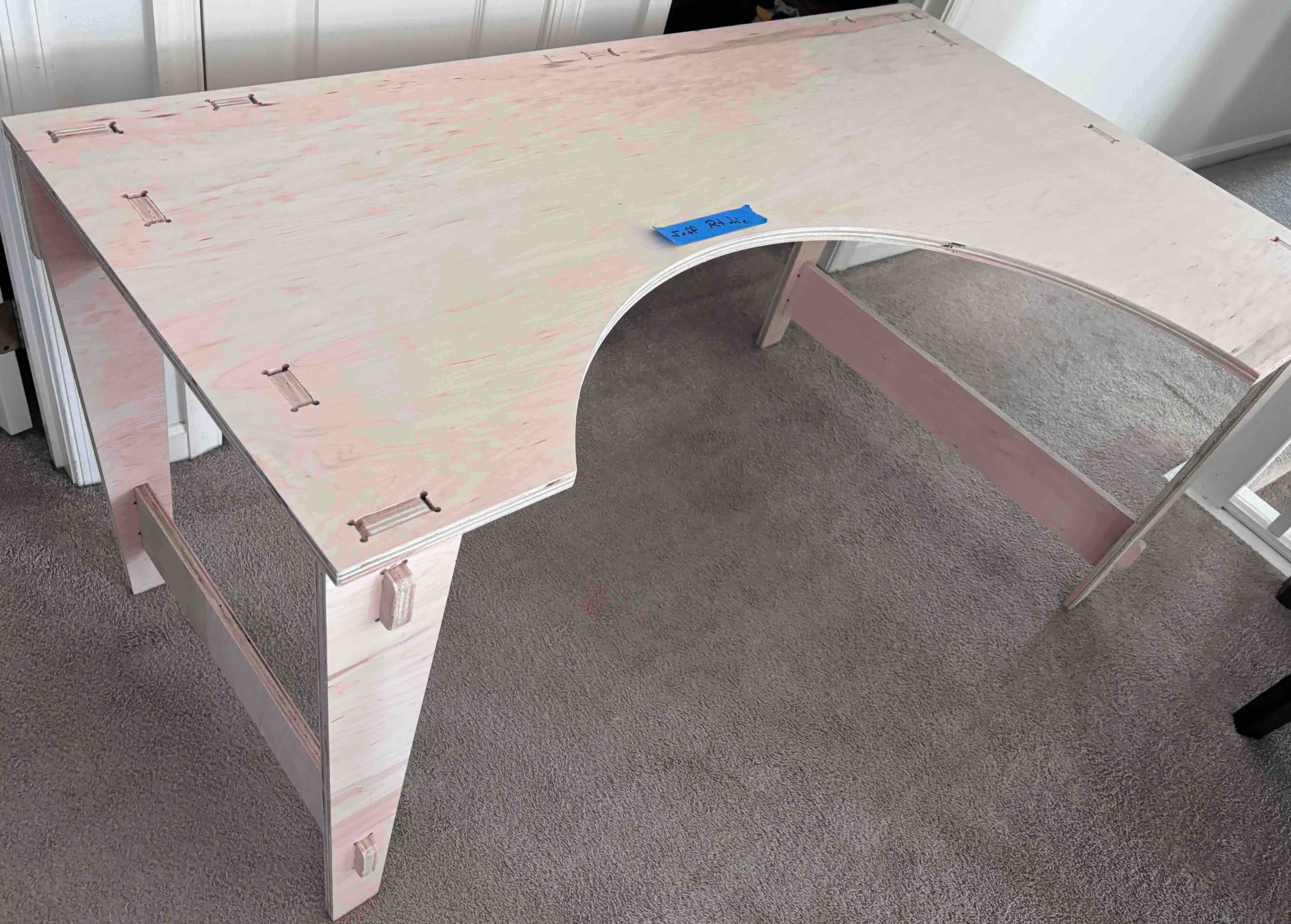
I sanded the individual faces and edges and assembled the parts. The parts were meant to be press fit and because the test joint worked without adding a clearance, I didn't add any clearance for the cuts, thinking that I could always sand to incrementally remove material, but I would be hard presssed to add material.
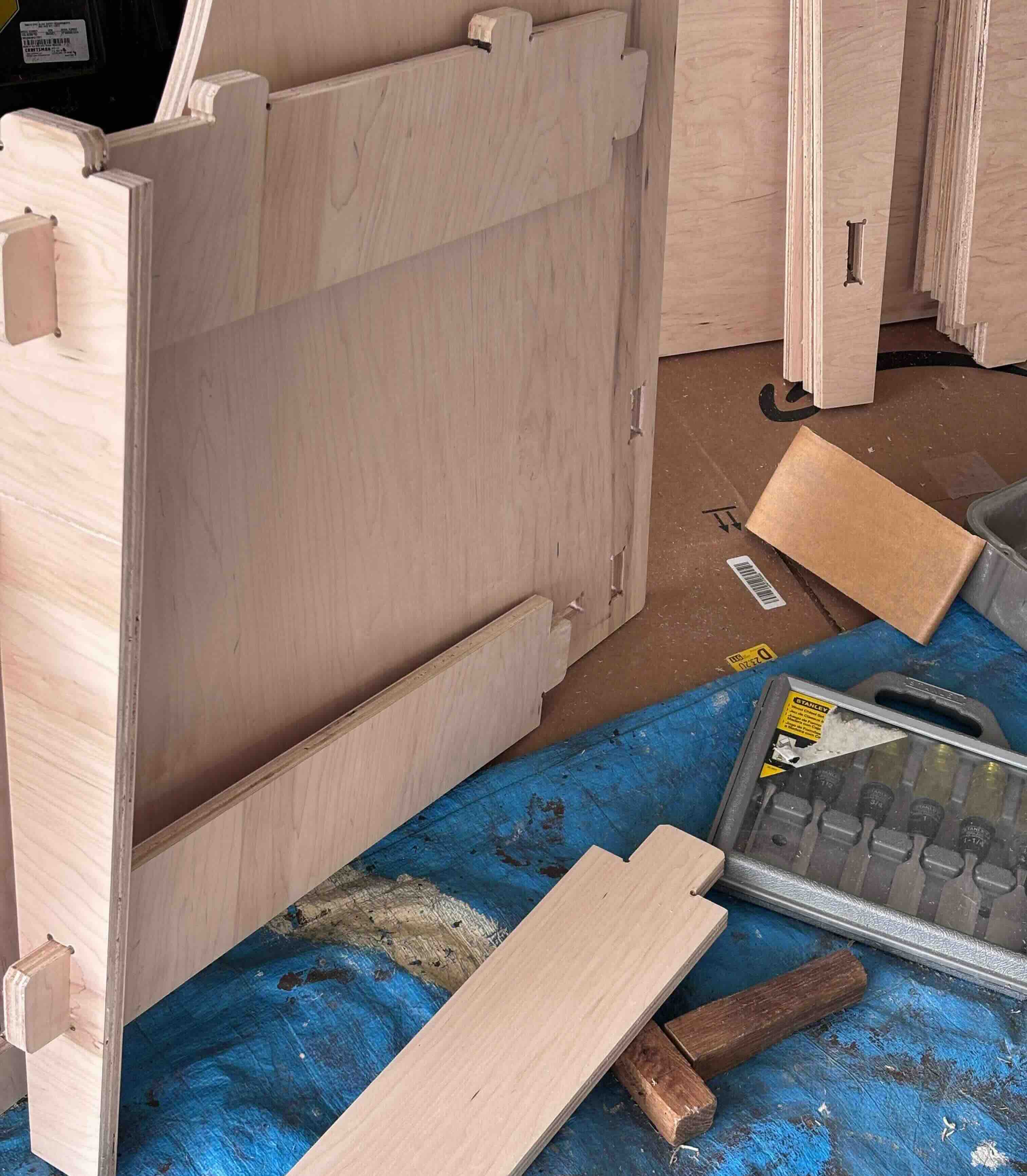
The joints were probably too tight and should have had a bit more clearance. That being said, the joints are exceptionally stable. To get the parts to fit togther, I placed a piece of wood on the desk part and used a wooden mallet. I beat the hell out of that piece of wood, but the parts came together perfectly.
Done.