Week 04 Embedded-Programming
Welcome to Fab Academy week 04, in which I get to dust off my Arduino IDE and try to remember how to program...
For the fourth week we were charged with the following assignment:
- demonstrate and compare the toolchains and development workflows for available embedded architectures
- browse through the data sheet for a microcontroller
- write and test a program for an embedded system using a microcontroller to interact (with input &/or output devices) and communicate (with wired or wireless connections)
- extra credit: assemble the system
- extra credit: try different languages &/or development environments
Embedded Program
Chip Comparison
My goal in this comparison is to understand what functions or use cases are afforded by each chip, as well as those uses for which each chip is not well-suited. I am planning on using the RP2040 for this week's embedded programming assignment and would like to determine which chip or chips I will use for my final project.
Because I am remote, I worked on this assignment alone. For this week's comparison, I referred to five data sheets:
SAMD21E18
Chip DatasheetBoard Datasheet
RP2040
Chip DatasheetBoard Datasheet
ATTINY412
Chip DatasheetI worked through the data sheets and filled out the chart below:
| SAMD21E18 | RP2040 | ATTINY412 | |
| Architecture | ARM Cortex-M0+ | Dual ARM Cortex-M0+ | 8 bit AVR |
| Clock Speed | 48MHz | 133MHz | 20MHz |
| SRAM | 32KB | 264KB | 256B |
| Flash | 256KB | External | 4KB |
| Input Voltage | 5v | 3.3v | 1.8–5.5v, 3v typical |
| IO Voltage | 3.3v | 1.8–3.3v | 3v, unless stated otherwise |
| #GPIO pins | 38 | 30 | 6 |
| PWM pins | 10 | 16 (8 two channel) | 4 (2 two channel) |
| DAC/ADC | 1 10-bit, 350ksps | 4 input ADC | 1 8-bit DAC, 10-bit 115 ksps ADC |
| UART | 1 | 2 | 1 |
| i2C | 1 | 2 | 1 |
| SPI | 1 | 2 | 1 |
| Chip Datasheet | Chip Datasheet | Chip Datasheet | Chip Datasheet |
| Board example | Xiao SAMD21 | XIAO RP2040 | NA |
| Board Datasheet | Board Datasheet | Board Datasheet | NA |
| Software Compatible |
Arduino CircuitPython MicroPython |
Arduino PlatformIO MicroPython CircuitPython tinyGo Rust Zephyr |
PlatformIO Arduino IDE |
| USBC | Y | Y | NA |
| Board Dimensions | 23.5×17.5×3.5 mm | 21×17.8 mm | NA |
| Board pinout | board pinout | board pinout | NA |
| # GPIO pins board | 14 | 14 | NA |
| # Digital Pins board | 11 | 11 | NA |
| # Analog Pins board | 11 | 4 | NA |
| Wifi | no | no | NA |
| Bluetooth | no | no | NA |
I uploaded the data sheets for the three chips and used the following prompt on chatgpt 5.2 to ensure that what I had written was correct.
I am a student in the fab academy and this week we are working on embedded programming. I will use this data sheet to understand the capabilities of the RP2040 chip, the ATTINY 412 and the SAMD21E18 chip- and their corresponding boards (XIAO SEEED series). My goal is programming and eventually designing and fabricating pcbs that use these chips. Do not respond at present. Just wait for me to upload the datasheets for the three chips and a table I am filling out. Afterwards, I will ask you questions. Please refer to the fab academy curriculum and these data sheets. As always, ask me questions to clarify the context of the request and my intent.https://chatgpt.com/share/6991efd3-baf4-800f-974c-08ef759a259e
The exchange was extremely helpful in that it prompted me to think about WHY I am looking at these chips and what elements of this comparison would be important, given my short term and long term goals. Short term, I want to be able to draft an embedded program. Long term, I need to consider which chips would be best suited for the needs of my final project.
Interestingly, the RP2040 makes the most sense for my final project, given its processing power. The RP2040’s lack of Flash memory pretty much means that in my board I will to provide that memory externally. The RP2040 would be well suited to meeting the demands of controlling a large number of LEDs and possibly sound and managing input.
The SAMD21 is a possible alternative to the RP2040, but the ATTINY could be useful in creating edge devices that would communicate with the RP2040.
For the circuit design week, I’ll need the pinout of the actual RP2040 chip, rather than the XIAO2040 pinout.
RP2040 MicroController Pinout
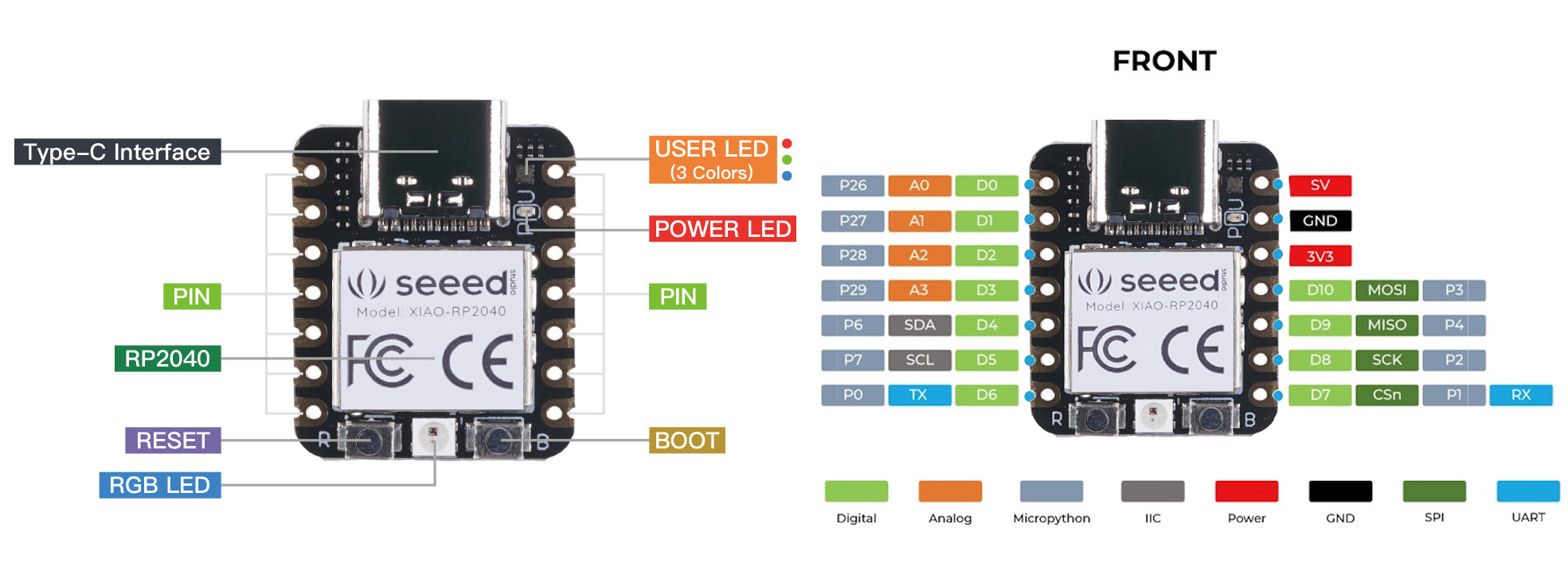
Pinout Legend- taken from data sheet
| GPIOx General-purpose digital input and output. | RP2040 can connect one of a number of internal peripherals to each GPIO, or control GPIOs directly from software. |
| GPIOx/ADCy | General-purpose digital input and output, with analogue-to-digital converter function. The RP2040 ADC has an analogue multiplexer which can select any one of these pins, and sample the voltage. |
| QSPIx | Interface to a SPI, Dual-SPI or Quad-SPI flash device, with execute-in-place support. These pins can also be used as software-controlled GPIOs if they are not required for flash access. |
|
USB_DM and USB_DP |
USB controller, supporting Full Speed device and Full/Low Speed host. A 27Ω series termination resistor is required on each pin, but bus pullups and pulldowns are provided internally. |
| XIN and XOUT | Connect a crystal to RP2040’s crystal oscillator. XIN can also be used as a single-ended CMOS clock input, with XOUT disconnected. The USB bootloader requires a 12 MHz crystal or 12 MHz clock input. |
| RUN | Global asynchronous reset pin. Reset when driven low, run when driven high. If no external reset is required, this pin can be tied directly to IOVDD. |
|
SWCLK and SWDIO |
Access to the internal Serial Wire Debug multi-drop bus. Provides debug access to both processors and can be used to download code. |
| TESTEN | Factory test mode pin. Tie to GND. |
| GND | Single external ground connection, bonded to a number of internal ground pads on the RP2040 die. |
| IOVDD | Power supply for digital GPIOs, nominal voltage 1.8 V to 3.3 V |
| USB_IOVDD | Power supply for internal USB Full Speed PHY, nominal voltage 3.3 V |
| ADC_IOVDDD | Power supply for analogue-to-digital converter, nominal voltage 3.3 V |
| VREG_IOVDD | Power input for the internal core voltage regulator, nominal voltage 1.8 V to 3.3 V |
| VREG_VOUT | Power output for the internal core voltage regulator, nominal voltage 1.1 V, 100 mA max current |
| DVDD | Digital core power supply, nominal voltage 1.1 V. Can be connected to VREG_VOUT, or to some other board-level power supply. |
Embedded Programming
As I am remote, I don't have access to the Fab Academy boards that are referred to in the embedded programming lesson for the week. For the purposes of this week's individual assignment, I'll be programming the Seeed Xiao RP2040 board. I have three, so I soldered pins to one to breadboard. I know, Neil hates breadboards.
I will use through hole components for the purposes of class this week.
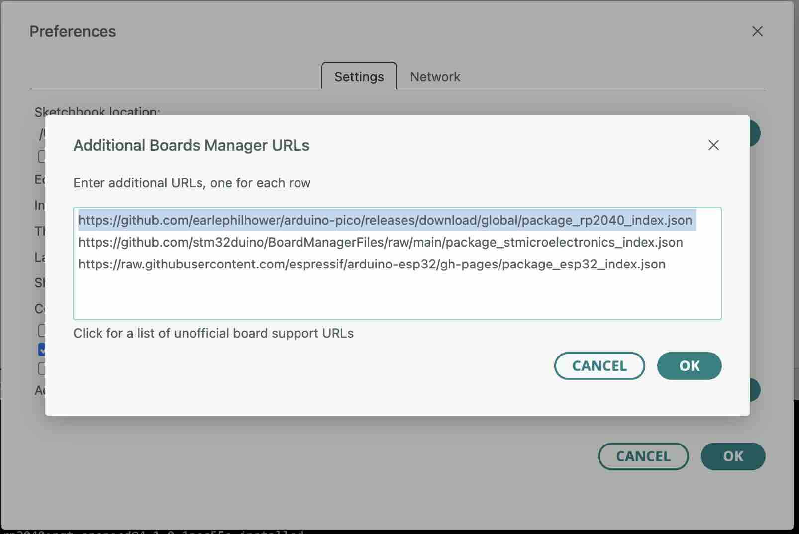
In the Arduino IDE, I added the XIAORP2040 board and the corresponding library, and added the URL for the board.
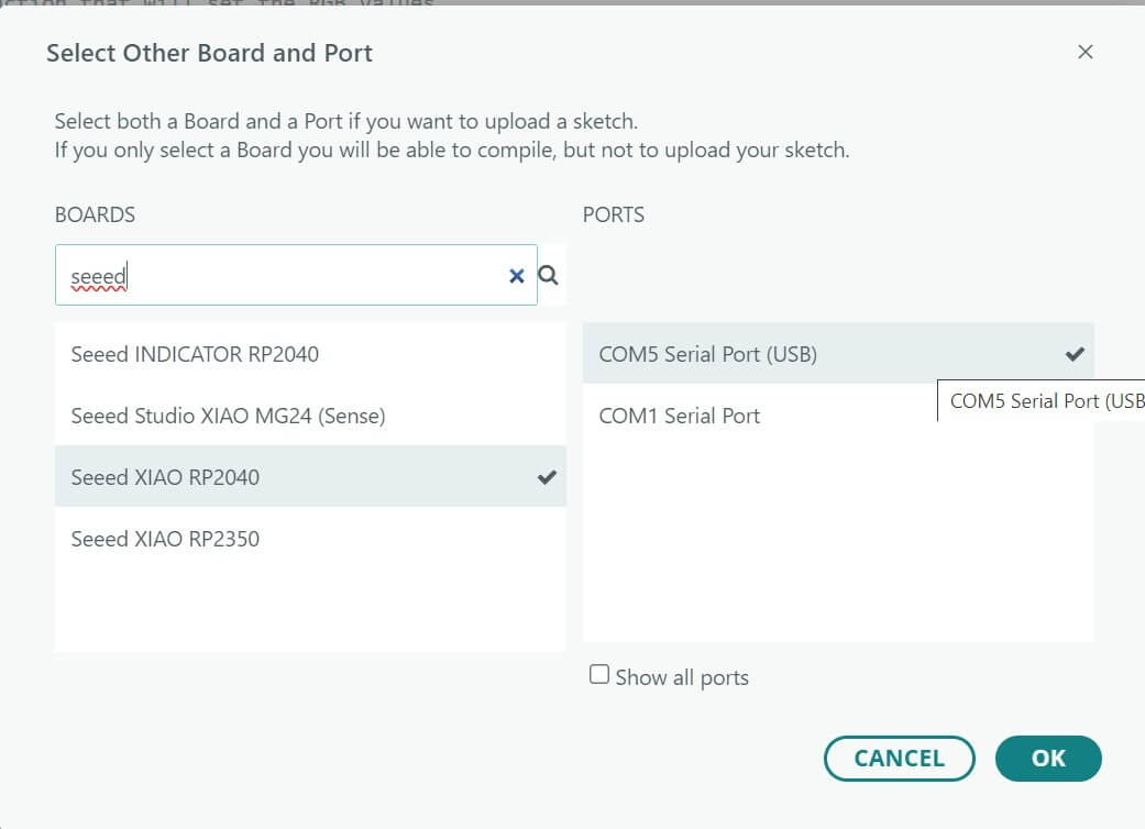
I then selected the board and port.
First, I wanted to use an existing sketch to see how the bootloader on the Xiao RP2040 works. To do that, I will need to build out the circuit that it uses.
To figure out the pinout for the board, I looked at
https://fabacademy.org/2026/classes/embedded_programming/RP2040/RP2040-XIAO-pinout.jpgTo figure out how the testing board was built, I looked at the following page:
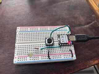
https://fabacademy.org/2026/classes/embedded_programming/RP2040/hello.button-blink.RP2040.jpgI tried to identify the components in the screen, which looks like a button, a 10001 SM resistor, and an LED.
It took me a while to figure out how to use the bootloader in Arduino. I had pressed both reset and boot and then unplugged and plugged back in the usb c cable. I had looked at the XIAO RP2040 pin out to figure out which was which.
I could figure out the circuit by the traces. I used a through hole button, a 100 ohm resistor, and an LED with 3.2v drop.
In programming, I relied on the pin out of the XIAO RP2040 board. For the purposes of building my own PCBs, I will need to be aware of the different pinout in the chip. I changed Neil's code to reflect different pins- D7 and D0. For some reason, the code would only work when I added a D to the pin number. I played around with revising Neil’s hello button blink sketch for RP2040. I wanted to practice writing functions, so I created a function checkSerial() and called it in an if statement. I wanted to use an if statement to flash the lights if I type hello into the serial monitor. I used the code if (serialInput == "hello") …flash the LED three times, but it wouldn’t work.
To understand why it was not working I used chatgpt5.2
I am programming using C on arduino IDE for a XIAO RP2040. THe button and LED work and the checkSerial function works, but I can't get the LEDs to flash when you write hello. // hello.button-blink.RP2040.1.ino // Jeff Ritchie 02/13/26 // FabAcademy // Based on Seeed XIAO RP2040 button, blink, echo hello-world, single core // Neil Gershenfeld 12/28/23 // This work may be reproduced, modified, distributed, // performed, and displayed for any purpose, but must // acknowledge this project. Copyright is retained and // must be preserved. The work is provided as is; no // warranty is provided, and users accept all liability. // add RP2040 core // https://github.com/earlephilhower/arduino-pico #define led_pin D7 // pin 7 #define button_pin D0 // pin 0 bool button_up = true; String serialInput = ""; //function that will check serial input void checkSerial(){ serialInput = Serial.readString(); //sets serial input variable to result of readString() Serial.print("you typed: "); Serial.println(serialInput); } void setup() { pinMode(led_pin,OUTPUT); pinMode(button_pin,INPUT_PULLUP); Serial.begin(115200); Serial.setTimeout(10); } void loop() { if (Serial.available()){ checkSerial(); //run check serial function } if (serialInput == "hello") { digitalWrite(led_pin,HIGH); //blink lights delay(100); digitalWrite(led_pin,LOW); delay(100); digitalWrite(led_pin,HIGH); delay(100); digitalWrite(led_pin,LOW); serialInput = ""; //reset serialInput variable } if ((digitalRead(button_pin) == LOW)) { digitalWrite(led_pin,HIGH); Serial.println("button down"); } else if ((digitalRead(button_pin) == HIGH)) { digitalWrite(led_pin,LOW); } } https://chatgpt.com/share/699308f1-265c-800f-838f-1aeb5b6725ea Interestingly, it revealed that the serial monitor was reading hello + the line ending:
"hello\n"
"hello\r\n"
This makes perfect sense and I had completely forgot that it does that. I changed the checkSerial () function to include trim() and uploaded the code to the RP2040. I added two if statements to check for whether I typed hello or world- which would cause the LED to blink 3 and five times respectively. I uploaded the sketch to the RP2040.
The code and circuit function.
hello_button_blink_RP2040_1_revised.ino
Embedded programming part 2
To prepare for my final project, I figured I should become comfortable programming addressable LEDs. To that end, my goal for this week is to program addressable LEDs using the RP2040.
To do this, I referred to the following sources:
Burgess, Phillip. “The Magic of NeoPixels | Adafruit NeoPixel Überguide | Adafruit Learning System.” Accessed February 13, 2026. https://learn.adafruit.com/adafruit-neopixel-uberguide/the-magic-of-neopixels.
Chrome for Developers. “Read from and Write to a Serial Port | Capabilities.” Accessed February 12, 2026. https://developer.chrome.com/docs/capabilities/serial.
“Serial | Arduino Documentation.” Accessed February 12, 2026. https://docs.arduino.cc/language-reference/en/functions/communication/serial/.
“Neopixel RGB 5050 LED with Integrated Driver Chip Data Sheet.” Accessed February 14, 2026. https://mm.digikey.com/Volume0/opasdata/d220001/medias/docus/973/3094_Web.pdf.
The Arduino library I needed to download is:
Adafruit Industries. Adafruit/Adafruit_NeoPixel. C++. December 12, 2012, Accessed February 12, 2026. https://github.com/adafruit/Adafruit_NeoPixel.
I followed the Adafruit tutorial at https://learn.adafruit.com/adafruit-neopixel-uberguide/basic-connections and used the strandtest.ino example sketch as a starting point.
First, I had to build out the circuit. Because I had cut it previously, I soldered hookup wire (22awg) to the leads on the neopixel strand. I added a 470 ohm resistor to the DM pin. ADAfruit calls for adding a capacitor (1000 uF CAPACITOR between NeoPixel strip's + and – connections), but I held off on that.
The Neopixels require a higher voltage and ampage than the RP2040 can provide. As as consequence, I needed to run two 22awg wires from a 4.5 v battery pack (3 x 1.5v batteries) to the power and ground rail of the breadboard. I connected the ground rail to the RP2040 ground, but kept the voltage rail unconnected to the board. The neopixels data line also requires a higher voltage than what is provided by the RP2040. I am only using 54 LEDs right now, but for the final project I will likely need to add a logic converter. The circuit looks like this:
The RP2040 pinout slightly differs from the Arduino on which the Adafruit sketch was based (the digital pins seem to require a D as in D6).
The circuit function as intended.
Revised Neopixel SketchI changed the circuit and revised the sketch to include a button that when pressed would change the LEDs. Because the different neopixel functions run all the way through without a break, the microcontroller is essentially blocked from doing anything until the function ends. The button works—but the delay caused by the function running until completion makes it hard to understand that the button actually controls the output of the neopixels.
Problems to solve:
- understand how the neopixel library functions.
- Program so that the neopixels don’t block further inputs/or functions on the microcontroller
- Understand how to turn on or change the color of the LEDs- say from white low brightness to red and changing brightness.
I began working through the Neopixel library Adafruit Industries. Adafruit/Adafruit_NeoPixel. C++. December 12, 2012, Accessed February 15, 2026. https://github.com/adafruit/Adafruit_NeoPixel.
The chipsets supported by this library include:
- AVR ATmega and ATtiny (any 8-bit) - 8 MHz, 12 MHz and 16 MHz
- Teensy 3.x and LC
- Arduino Due [sic Duo?]
- Arduino 101
- Arm® Cortex®-M7/M4 - RENESAS/STM (Arduino UNO R4, Arduino Portenta H7, Arduino Giga R1)
- ATSAMD21 (Arduino Zero/M0 and other SAMD21 boards) @ 48 MHz
- ATSAMD51 @ 120 MHz
- Adafruit STM32 Feather @ 120 MHz
- ESP8266 any speed
- ESP32 any speed
- WCH CH32 @ 48 MHz and higher speeds
- Nordic nRF52 (Adafruit Feather nRF52), nRF51 (micro:bit)
- Infineon XMC1100 BootKit @ 32 MHz
- Infineon XMC1100 2Go @ 32 MHz
- Infineon XMC1300 BootKit @ 32 MHz
- Infineon XMC1400 2Go @ 48 MHz
- Infineon XMC4700 RelaxKit, XMC4800 RelaxKit, XMC4800 IoT Amazon FreeRTOS Kit @ 144 MHz
- Sipeed Maix Bit (K210 processor)
The functions available in this library are:
- begin()
- updateLength()
- updateType()
- show()
- delay_ns()
- setPin()
- setPixelColor()
- fill()
- ColorHSV()
- getPixelColor()
- setBrightness()
- getBrightness()
- clear()
- gamma32()
My next step was to change the code so that all LEDs are red and slightly pulse. I used chatgpt 5.2 to explain how the code functions using the following prompt:
Explain how each line of the following arduino sketch functions. Then, provide details as to how I can change the color so that all pixels are red that gently pulse.
// adafruit neopixel example sketch
#include
#ifdef __AVR__
  #include
#endif
#define PIN        D6 //RP2040 uses D6 rather than pin 6
#define NUMPIXELS 56 //

Adafruit_NeoPixel pixels(NUMPIXELS, PIN, NEO_GRB + NEO_KHZ800);
#define DELAYVAL 500

void setup() {
#if defined(__AVR_ATtiny85__) && (F_CPU == 16000000)
  clock_prescale_set(clock_div_1);
#endif
  pixels.begin();
}
void loop() {
  pixels.clear();
for(int i=0; i I worked through the response and changed the code based on the feedback. The code worked. I have three variations of Neopixel effects, but for the purposes of saving data, I will just post the one video of the breathing effect sketch.
Pulse Animation
Travelling Pulse Animation
Breathing Animation
What I learned
I better understand how to read datasheets.
I have an idea of the chip I'll use in my final project
I have resources to use in understanding addressable LEDs