The sediment trap
Progress
- I modelled a first draft of the disk dispenser as part of the Computer-Aided Design assignments.
- After discussion with the biologists, it would be nice if the input grid could be made out of copper.
It would prevent marine organisms to fix themselves on the grid (a phenomenon known as biofouling).
I imagine making it out of interlocked combs, They will be manufactured with CNC machine or maybe water-cutter.
Disk dispenser 3D model
I design the assembly of the disk dispenser:
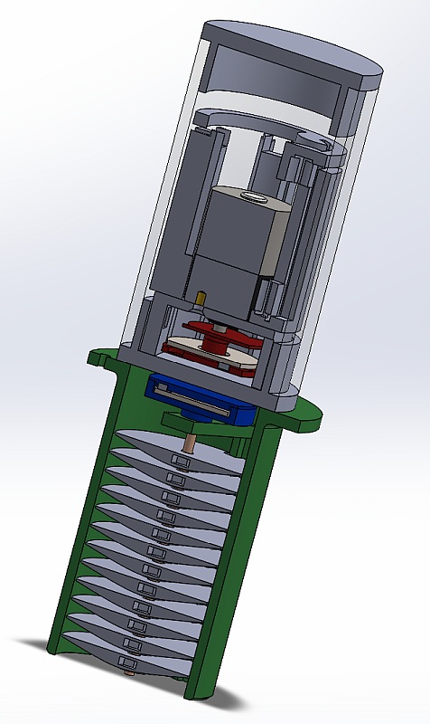
The disks are mounted on a threaded rod.
The rod is connected to a coupling disk. In this disk, 6 or 8 magnets will be embedded to create a magnetic coupler with a similar coupling disk that will be inside a watertight enclosure.
This disk will be driven by an electrical motor, enclosed in the same enclosure with the electronics and battery.
Next step is an exploded view of the dispenser.
Entry grid
I have 3 ideas to make the entry grid:
- use 2-sided PCB: it has a copper surface and is lighter and more rigid that a full copper piece
- use a copper-infused PLA filament to 3D print the grid in one piece. It will be easier to manufacture and assemble.
However, there is the question about the anti-fouling efficiency of this material. - use copper foil to cover the grid wall. The wall would be laser-cut in a plastic plate (material to be determined)
I will print a copper-PLA piece that will be placed next to the sediment trap during its first mission.
The idea is to test if it's fouling-proof, without risking the mission success.
global architecture
This is a view of the inside.
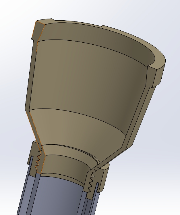
- At the top, there is the input funnel.
- The funnel is screwed in a adaptation piece. The trap should be easy to assemble and disassemble to allow transport by plane and samples retrieval under water.
- The adaptation piece is glued to a PVC pipe. This pipe will be the external body of the sediment trap.
- The sample tube will be put inside the PVC pipe. It will be a PMMA tube with a rubber cap at the bottom.
It will be hold in place between the bottom of the PVC tube and the bottom of the funnel. - The disk dispenser and the top part of the funnel needs to be added.
Electronics
Requirements
- Simple motor control: CW and CCW rotations, but no speed control.
- motor position sensor: we need to know how much turns the motor turns
- Real-time clock to count the number of days to wait between disk drops. No need for a "full" calendar.
- deep sleep mode: the system must works for one year on its battery. Each part must have a minimal quiescent current.
Motor choice
DC vs. stepper
Motor control circuit
To minimize the quiescent current, the best choice is to make a H-bridge with discrete MOSFET transistors. PWM won't be needed as the motor will always be turning at full speed.
Real time clock
Two solutions:
- use an external RTCC that will wake the microcontroller up when needed
- use the internal microcontroller oscillator to implement a software RTC
The choice will mainly depend on the power consumption of each solution.