Research
Output Devices
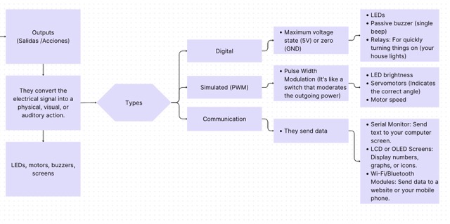
Output devices convert the electrical signal from a microcontroller into a physical, visual, or auditory action.
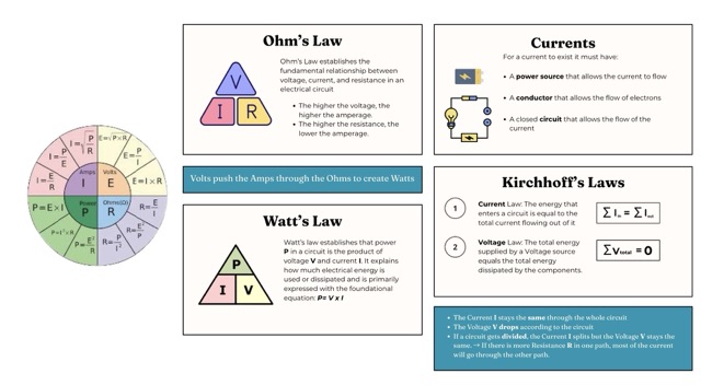
I started by reviewing Ohm's and Kirchhoff's Laws to build a solid foundation before working with output devices.
I then went deeper into output devices and also reviewed my Week 4 — Embedded Systems Map, which helped me recall the different categories of output devices.
Motor Info
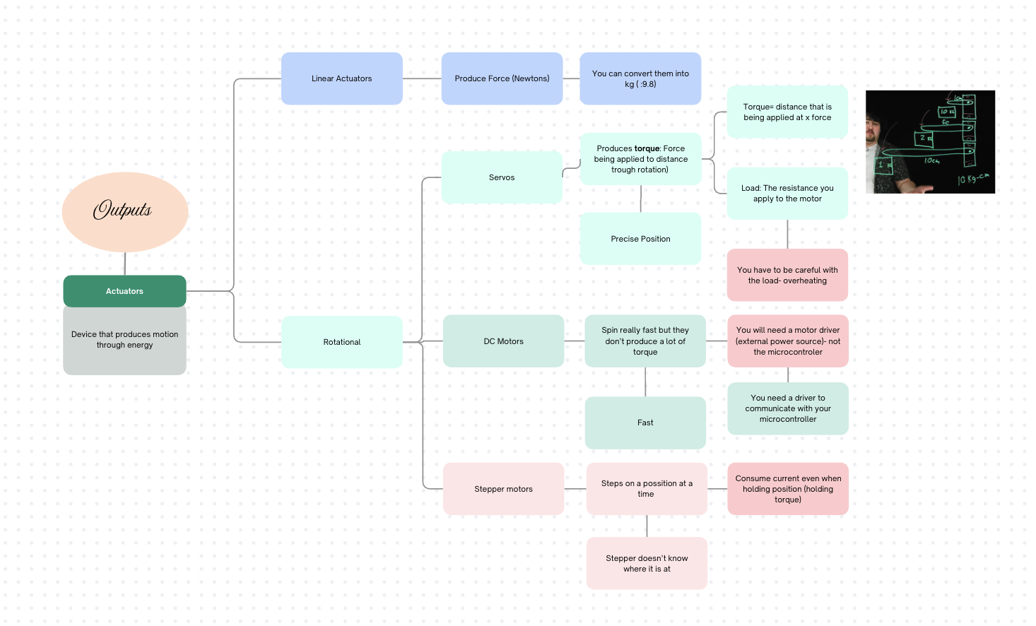
I found motors particularly interesting, so I began researching how they operate in more depth. I focused on a few core concepts and started by creating a mind map to understand the different types of actuators available and the situations they are best suited for.
Why you cannot connect a motor directly to a microcontroller
Based on Ohm's and Kirchhoff's laws reviewed in Week 6, connecting a motor directly to a microcontroller pin is not possible. The motor will attempt to draw more current (amps) than the microcontroller pins can supply, which causes the board to overheat and fail.
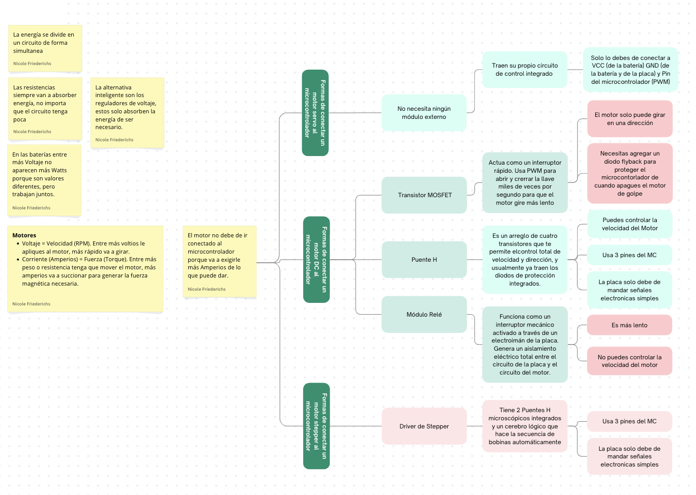
To prevent this, external components must be used as a bridge. These vary depending on the motor type:for example, MOSFETs for DC motors or dedicated driver ICs for stepper motors. I did another diagram to see wich one is used for each motor.
Why I Chose a Servo
Since my final project involves a kinetic origami panel that reacts to air quality, I needed to decide between a standard DC motor and a servo for the folding mechanism. Because the design does not require continuous rotation speed control — but instead demands reasonably precise angular movement to fold and unfold the structure — a servo is the better choice.
ADVANTAGES OF THE SERVO
- Precise angular position control without needing continuous rotation feedback.
- More energy-efficient than a stepper motor — it does not drain a large amount of current just to hold its position.
- Has an internal controller, which simplifies the external circuit significantly.
CONSIDERATION
- Standard servos are limited to a 180-degree rotation range.
- If a wider angle is needed for the origami folds, a custom gear ratio can be implemented to extend the effective range.
Connecting
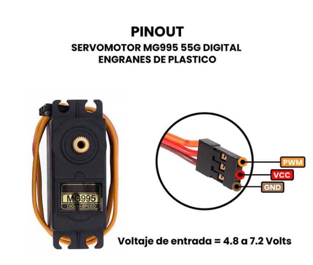
Connecting a servo is straightforward because it already has an internal controller. It uses three wires.
Servo Wiring — Three Wires
Power (VCC) — Connected to the 5 V power supply.
Ground (GND) — Connected to the common ground of the circuit.
Signal — Connected directly to a digital PWM pin on the microcontroller.
MG995 Datasheet
To connect the servo correctly, I consulted the MG995 datasheet, where I found its pinout.
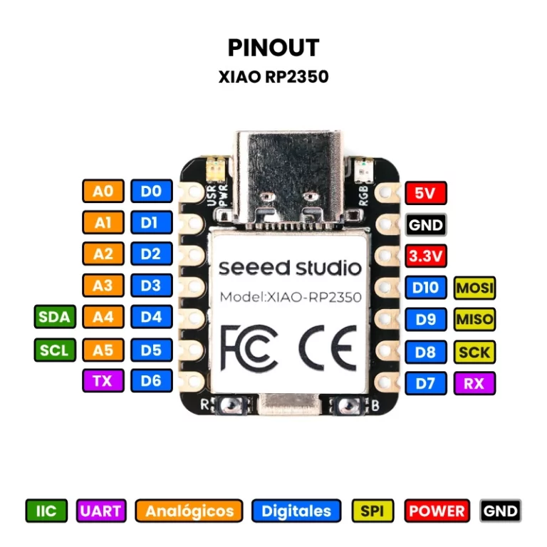
PCB Pin Verification
I also checked the XIAO Pinout to confirm I was using the correct pins before making the connections.
FINAL CONNECTIONS — MG995 → PCB
MG995 VCC → PCB PowerMG995 GND → PCB GNDMG995 PWM → PCB Pin D0
Programming
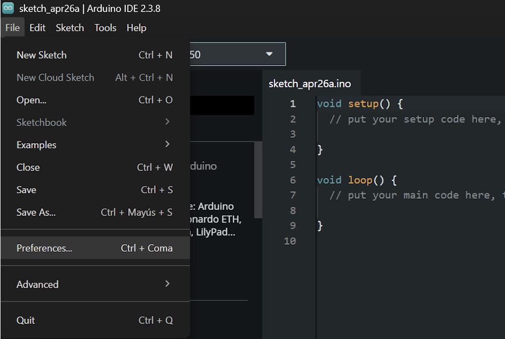
Once the hardware was connected, I programmed the XIAO RP2350 using Arduino IDE to read the live acceleration values from the MPU6050. The first step was to connect the PCB to Arduino IDE.
CONNECTION PROCESS:
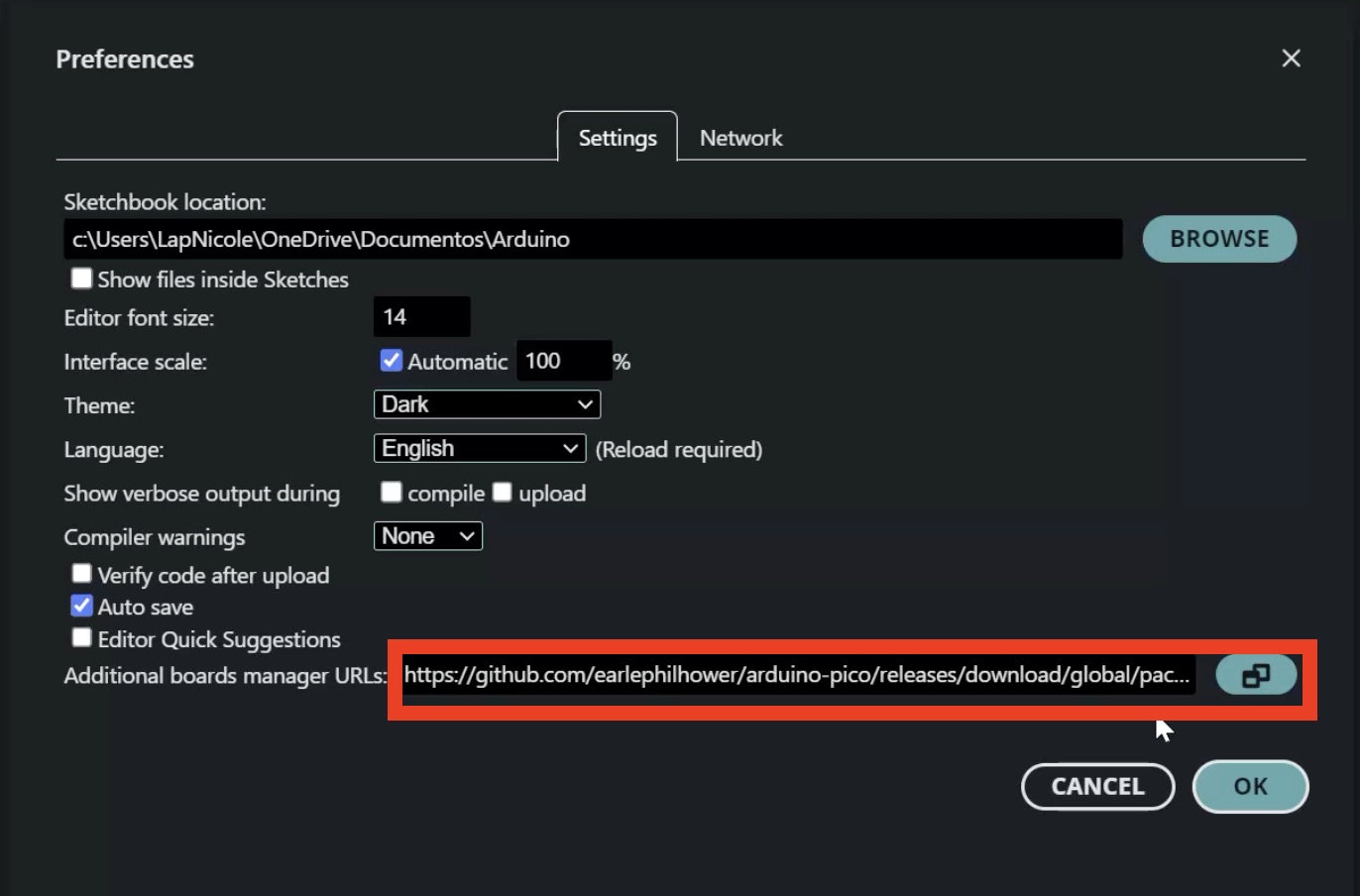
1. Open Arduino IDE and go to File > Preferences.
2. In Additional Boards Manager URLs, paste this link: https://github.com/earlephilhower/arduino-pico/releases/download/global/package_rp2040_index.json
3. Go to Tools > Board > Boards Manager.
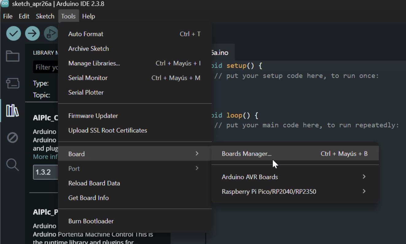
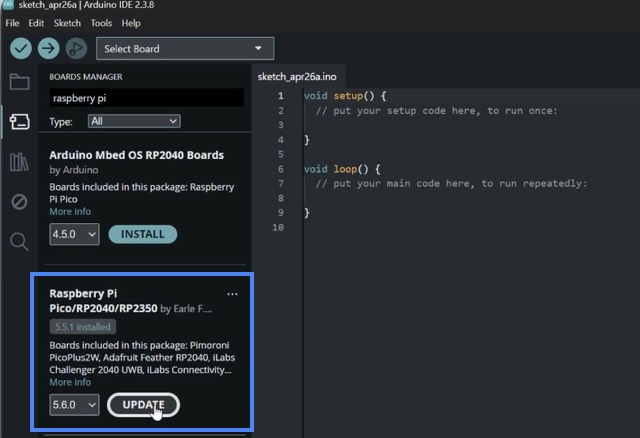
4. Search for Raspberry Pi Pico / RP2040 / RP2350 package and install it.
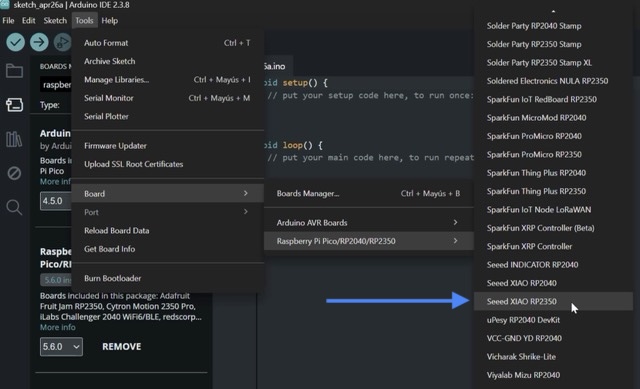
5. Once installed, select: Tools > Board > Raspberry Pi RP2350 Boards > Seeed XIAO RP2350.
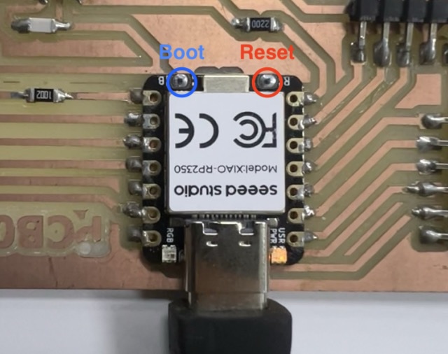
6. Connect the XIAO board to the computer using USB-C.
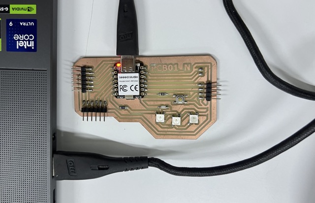
7. Press and hold the BOOT button. Press and release the RESET button. Release the BOOT button so the board enters upload mode.
I installed the servo Library:
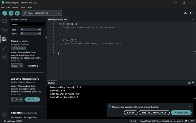
To control the servo, I used Pulse Width Modulation (PWM) to send signals to the motor's internal controller, telling it exactly which angle to move to. The goal of the test code was to make the servo sweep back and forth to simulate the folding motion of the origami.
Source Code
#include <Servo.h>

Servo miMotor;
int pinServo = 0;
int pinBoton = 7;

void setup() {

  miMotor.attach(pinServo);
  miMotor.write(0);

  pinMode(pinBoton, INPUT_PULLUP);
}

void loop() {
  if (digitalRead(pinBoton) == LOW) {

    miMotor.write(90);
    delay(500);

    miMotor.write(180);
    delay(500);

    miMotor.write(0);
    delay(500);
  }

  delay(50);
}Code Breakdown
Libraries & Variables
- #include <Servo.h> — imports the Arduino Servo library, which provides all the functions needed for PWM-based motor control.
- Servo miMotor — creates the Servo object that will be used to issue movement commands throughout the program.
- pinServo = 0 — defines pin D0 as the PWM signal output to the motor.
- pinBoton = 7 — defines pin D7 as the digital input for the push button.
Setup
- miMotor.attach(pinServo) — links the Servo object to pin D0 so that
write()commands generate the correct PWM waveform on that pin. - miMotor.write(0) — moves the servo to the 0° start position on power-up, ensuring a known initial state.
- INPUT_PULLUP — activates the microcontroller's internal pull-up resistor on the button pin. The pin reads HIGH (1) normally and LOW (0) when the button is pressed and connected to GND.
Loop — Button Check
- digitalRead(pinBoton) == LOW — checks whether the button is currently being pressed. Because of INPUT_PULLUP, a press pulls the pin to GND (LOW), triggering the condition.
The sweep routine runs only while the button is held. This makes the test repeatable and isolated from the rest of the program.
Sweep Routine
- miMotor.write(90) — moves the servo to the center position (90°).
- miMotor.write(180) — moves the servo to its maximum angle (180°).
- miMotor.write(0) — returns the servo to the initial position (0°).
- delay(500) — pauses 500 ms between each movement, giving the servo enough time to reach the target angle before the next command is issued.
Stability Pause
- delay(50) — a short pause at the end of each loop iteration. It reduces the button polling rate and prevents erratic readings caused by contact bounce.
Final Result
After uploading the code and connecting the power supply, the servo successfully moved to the programmed angles. Testing this output in isolation from the rest of the project provided the confidence needed to integrate it into the final kinetic structure.
Final Reflection:
During this week it was very interesting learning about the motors, thanks to this weeks I got to understand the electricity laws better.