Research
Input device:
An input device is an electronic component that detects a physical phenomenon and transforms it into electrical information that a microcontroller can interpret. Unlike output devices, which send actions outward, input devices allow the board to receive information from its surroundings.
Input signals can generally be divided into:
- Digital signals: only HIGH or LOW values.
- Analog signals: continuous variable values.
What is I2C?
I2C stands for Inter-Integrated Circuit. It is a communication protocol that allows two or more electronic devices to talk to each other using only two wires.
These two wires are:
- SDA → sends the data
- SCL → controls the clock timing
Instead of needing many cables for every signal, I2C simplifies the communication and lets the microcontroller receive multiple values continuously. This communication system is very useful because it allows sensors to send complex information without needing many pins.
What I learned from the group assignment:
During the group assignment, we analyzed several input devices using the oscilloscope and compared analog and digital responses. This helped me understand how different sensors behave electrically and prepared me to better interpret the accelerometer signals.
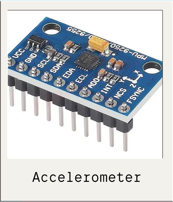
Accelerometer
MPU6050
For this week I used the MPU6050 accelerometer, which is a motion sensor capable of measuring acceleration in three different axes: X, Y, and Z.
This means the sensor can detect:
- left and right movement
- forward and backward tilt
- vertical acceleration
Unlike a basic digital input, this sensor continuously sends changing numerical values depending on how it is moved.
Main pins used:
- VCC (Voltage)
- GND
- SDA
- SCL
Why I chose this sensor:
I wanted to work with a more dynamic input that generated real live data instead of only an ON/OFF response. The accelerometer allowed me to visualize motion numerically and understand how continuous sensing works.
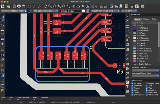
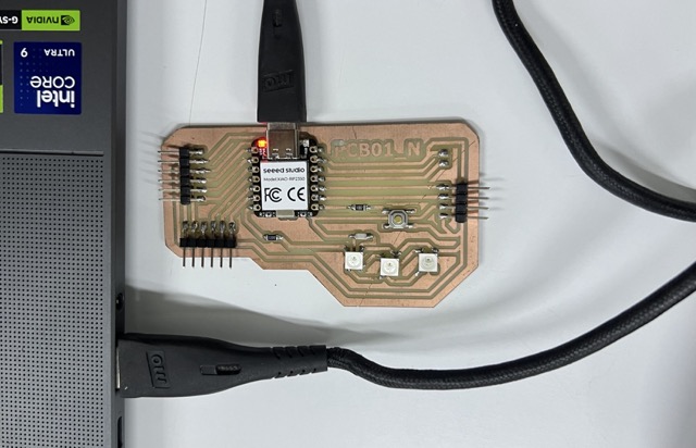
Connecting the PCB to the Accelerometer
To interface the sensor, I used the custom PCB I made during Electronics Production. In that previous board, I had already designed a small I2C module specifically to access SDA and SCL communication pins.This made it possible to directly connect the accelerometer to my board.
Connection process:
- MPU6050 VCC → PCB power
- MPU6050 GND → PCB GND
- MPU6050 SDA → PCB SDA pin (D4)
- MPU6050 SCL → PCB SCL pin (D5)
I connected the sensor using jumper wires to the exposed I2C module. To locate the correct pins, I used the Kicad document as a guide.
What I learned:
I learned that when working with communication sensors, wiring is much more sensitive than with simple digital components. A wrong SDA or SCL connection immediately stops all communication.
Programming
Once the hardware was connected, I programmed the XIAO RP2350 using Arduino IDE to read the live acceleration values from the MPU6050. The first step was to connect the PCB to Arduino IDE.
CONNECTION PROCESS:
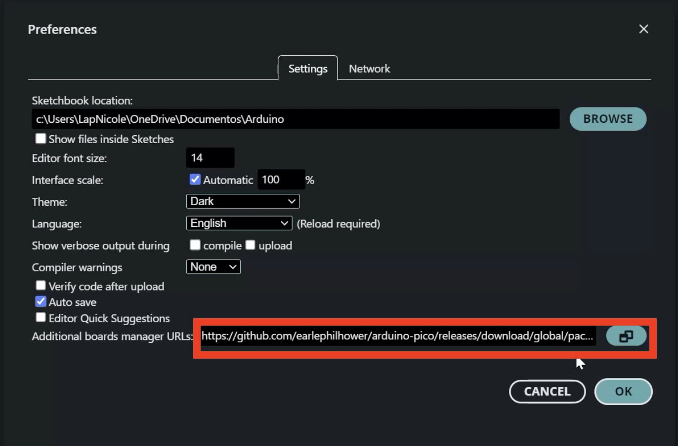
1. Open Arduino IDE and go to File > Preferences.
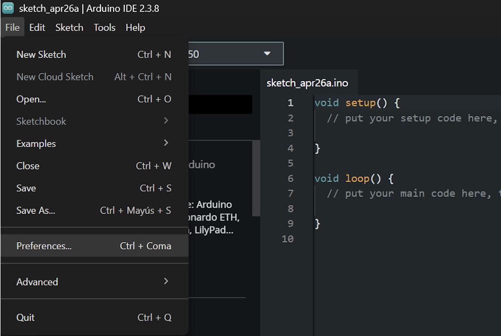
2. In Additional Boards Manager URLs, paste this link: https://github.com/earlephilhower/arduino-pico/releases/download/global/package_rp2040_index.json
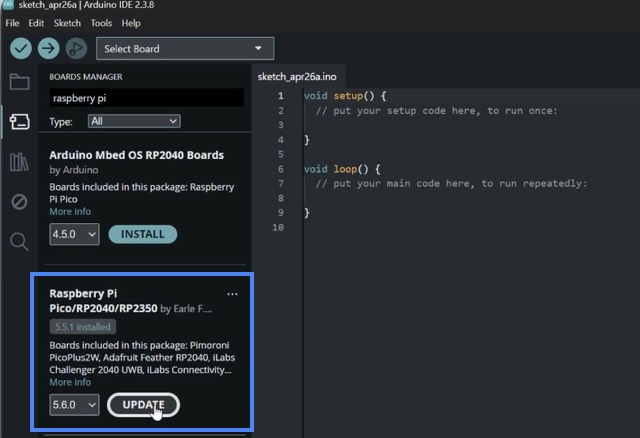
3. Go to Tools > Board > Boards Manager.
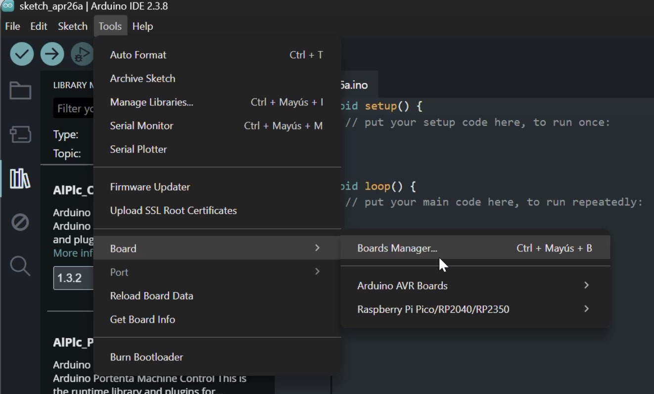
4. Search for Raspberry Pi Pico / RP2040 / RP2350 package and install it.
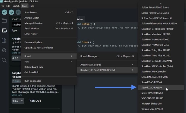
5. Once installed, select: Tools > Board > Raspberry Pi RP2350 Boards > Seeed XIAO RP2350.
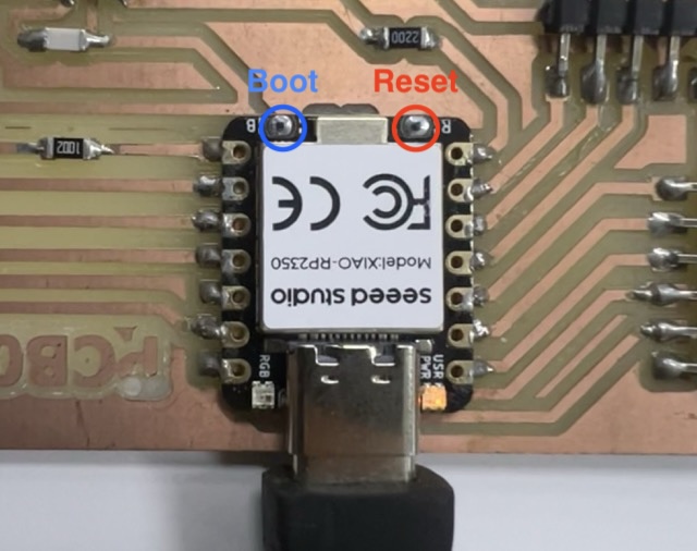
6. Connect the XIAO board to the computer using USB-C.
7. Press and hold the BOOT button. Press and release the RESET button. Release the BOOT button so the board enters upload mode.
Since I am not very good at programming jet I used Gemini to develop the code. This was the prompt:
Act as an expert electronics teacher and Arduino programmer. I am a beginner learning electronics and I want to write a code for the MPU6050 on pins D4 (SDA) and D5 (SCL).
I want to do this completely from scratch, without using the Wire library, just controlling the pins directly.
I need the code to calculate the movement velocity. To do this, please remove the normal gravity so it only detects when I actually move it. If I leave it still on the table, the velocity should slowly drop back to zero.
Finally, I want to watch the data on the Serial Plotter. Please multiply the results by 50 so the waves look bigger on the screen, and add a constant zero line as a reference.
Since you are an expert teacher, please add clear comments to the code and explain how the manual pin control (bit-banging) works in simple terms.
Instead of using a standard external library, I used a custom code that manually creates the I2C communication through bit-banging. This means the code itself controls the SDA and SCL pulses to talk directly to the sensor.
How the code works:
- It defines D4 and D5 as the communication pins.
- It creates small functions to manually send and receive I2C signals.
- In setup(), the code wakes up the MPU6050.
- In loop(), it asks the accelerometer for the X, Y, and Z raw values.
- It converts these raw values into acceleration values.
- It filters small unwanted vibrations.
- Finally, it prints the processed movement values in the Arduino Serial Monitor.
Final result of the code:
Every time I moved the sensor, the X, Y, and Z values changed live on screen, which confirmed that the input device was working correctly.
SOURCE CODE:
#define SCL_PIN D5
#define SDA_PIN D4
#define MPU_ADDR 0x68

// VARIABLES DE TIEMPO Y VELOCIDAD
unsigned long lastTime = 0;
float velocidad = 0.0;

// --- I2C BIT-BANGING FUNCTIONS ---
void i2c_start() {
  pinMode(SDA_PIN, OUTPUT);
  digitalWrite(SDA_PIN, HIGH); digitalWrite(SCL_PIN, HIGH);
  delayMicroseconds(5);
  digitalWrite(SDA_PIN, LOW); delayMicroseconds(5);
  digitalWrite(SCL_PIN, LOW);
}

void i2c_stop() {
  pinMode(SDA_PIN, OUTPUT);
  digitalWrite(SDA_PIN, LOW); digitalWrite(SCL_PIN, HIGH);
  delayMicroseconds(5);
  digitalWrite(SDA_PIN, HIGH); delayMicroseconds(5);
}

bool i2c_write(uint8_t byte) {
  pinMode(SDA_PIN, OUTPUT);
  for (int i = 0; i < 8; i++) {
    digitalWrite(SDA_PIN, (byte & 0x80) ? HIGH : LOW);
    byte <<= 1; delayMicroseconds(5);
    digitalWrite(SCL_PIN, HIGH); delayMicroseconds(5);
    digitalWrite(SCL_PIN, LOW);
  }
  pinMode(SDA_PIN, INPUT_PULLUP);
  digitalWrite(SCL_PIN, HIGH); delayMicroseconds(5);
  bool ack = (digitalRead(SDA_PIN) == LOW);
  digitalWrite(SCL_PIN, LOW);
  return ack;
}

uint8_t i2c_read(bool ack) {
  uint8_t byte = 0;
  pinMode(SDA_PIN, INPUT_PULLUP);
  for (int i = 0; i < 8; i++) {
    digitalWrite(SCL_PIN, HIGH); delayMicroseconds(5);
    byte = (byte << 1) | digitalRead(SDA_PIN);
    digitalWrite(SCL_PIN, LOW); delayMicroseconds(5);
  }
  pinMode(SDA_PIN, OUTPUT);
  digitalWrite(SDA_PIN, ack ? LOW : HIGH);
  digitalWrite(SCL_PIN, HIGH); delayMicroseconds(5);
  digitalWrite(SCL_PIN, LOW);
  return byte;
}

void setup() {
  Serial.begin(115200);
  pinMode(SCL_PIN, OUTPUT);
  pinMode(SDA_PIN, INPUT_PULLUP);

  delay(3000);

  i2c_start();
  i2c_write(MPU_ADDR << 1);
  i2c_write(0x6B);
  i2c_write(0);
  i2c_stop();

  lastTime = micros();
}

void loop() {
  // 1. ADQUISICIÓN DE DATOS (ACELERÓMETRO)
  i2c_start();
  i2c_write(MPU_ADDR << 1);
  i2c_write(0x3B);
  i2c_stop();

  i2c_start();
  i2c_write((MPU_ADDR << 1) | 1);
  int16_t ax_raw = (i2c_read(true) << 8) | i2c_read(true);
  int16_t ay_raw = (i2c_read(true) << 8) | i2c_read(true);
  int16_t az_raw = (i2c_read(true) << 8) | i2c_read(false);
  i2c_stop();

  // 2. CÁLCULO DEL TIEMPO (dt)
  unsigned long currentTime = micros();
  float dt = (currentTime - lastTime) / 1000000.0;
  lastTime = currentTime;

  // 3. CONVERSIÓN A m/s^2
  float ax = (ax_raw / 16384.0) * 9.81;
  float ay = (ay_raw / 16384.0) * 9.81;
  float az = (az_raw / 16384.0) * 9.81;

  // 4. AISLAR EL MOVIMIENTO PURO (Sin importar la rotación)
  // Calculamos la magnitud total y le restamos 1 Gravedad (9.81)
  float magnitudTotal = sqrt(ax*ax + ay*ay + az*az);
  float aceleracionDinamica = magnitudTotal - 9.81;

  // Filtro de ruido: Si el movimiento es muy leve, lo forzamos a 0
  if (abs(aceleracionDinamica) < 0.5) {
    aceleracionDinamica = 0;
    // Fricción matemática: Si está quieto, la velocidad cae a cero rápidamente
    velocidad *= 0.85;
  } else {
    // 5. INTEGRACIÓN (Aceleración -> Velocidad)
    velocidad += aceleracionDinamica * dt;
  }

  // 6. SERIAL PLOTTER CON "LUPA" VISUAL
  // Multiplicamos por 50 para exagerar los picos en la gráfica
  Serial.print("Base_Cero:0,"); // Línea de referencia estática
  Serial.print("Aceleracion_Amplificada:"); Serial.print(aceleracionDinamica * 50);
  Serial.print(",");
  Serial.print("Velocidad_Amplificada:"); Serial.println(velocidad * 50);

  delay(20);
}
Final Result
After connecting the MPU6050 to my custom PCB and uploading the code successfully, I obtained a fully working motion input system...
Problems encountered and solutions:
- I had to verify several times that SDA and SCL were connected to the correct pins.
How I fixed them:
- I checked every jumper wire carefully.
Final Reflection:
This week helped me understand that input devices work like the senses of a microcontroller.