PCB N02 — New Board Design
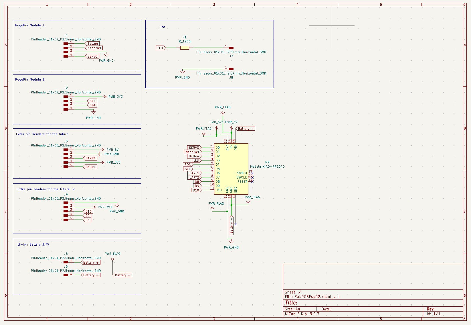
For this week and for my final project I needed a PCB with a XIAO ESP32-C6 microcontroller, so I started by designing this new board in KiCad. I followed the same steps from Week 6 — Electronics Design. This time I designed the board already taking my final project into account, so I began by thinking through which components I would need.
Electronic Architecture — Final Project Components
CORE COMPONENTS
- XIAO ESP32-C6 microcontroller
- ENS160 (VOC / CO₂) + AHT21 (Temp / Hum) sensor
- 3.7 V LiPo battery
- NeoPixel
- Switch + Button
- Servo motor MG995
OPTIONAL COMPONENTS
- PM sensor
- Photoresistor
Design Approach
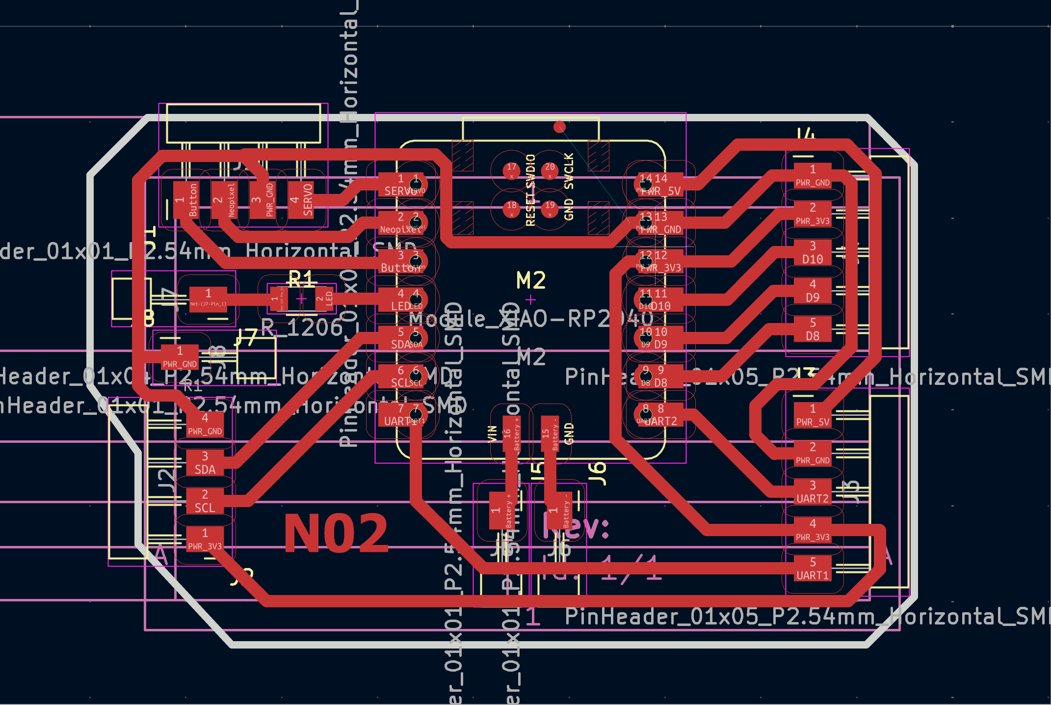
I built on the versatility of my previous board by adding pin headers for future attachments, since my idea is to connect the sensor module through pogo pins, but if those don't work as expected, I can use the pin headers. Once I had a general idea I built the schematic in KiCad and routed the traces in the PCB design view, following the same workflow as Week 6.
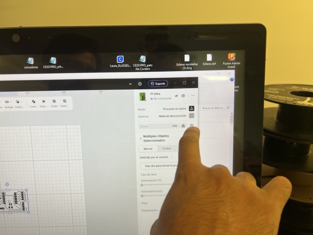
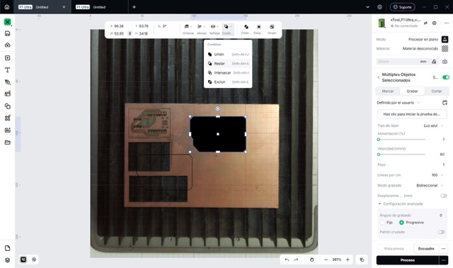
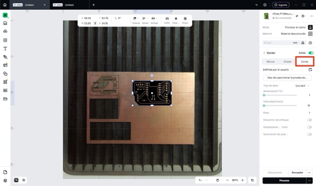
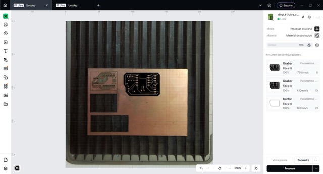
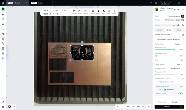
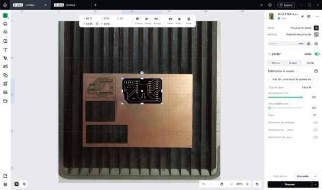
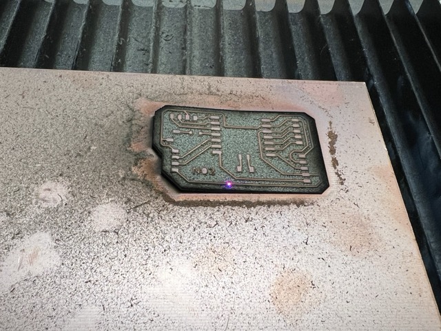
Fabrication — XTool Laser
I followed the same export process from Week 8 — Electronics Production: exported the PCB as Gerber from KiCad and converted it to PNG. However, this week I tried something new and made my PCB with the XTool laser. Below are the steps to reproduce it.

Problems & Lessons Learned
- The board warped slightly during cutting. It did not affect soldering, I hope I doesn't impact the board's long-term operation.
- I originally used the XIAO ESP32-C3 footprint because the C6 was not available. After finishing, I noticed the battery footprint did not match, so I swapped it for the XIAO RP2040 footprint, which is compatible with the board I have.
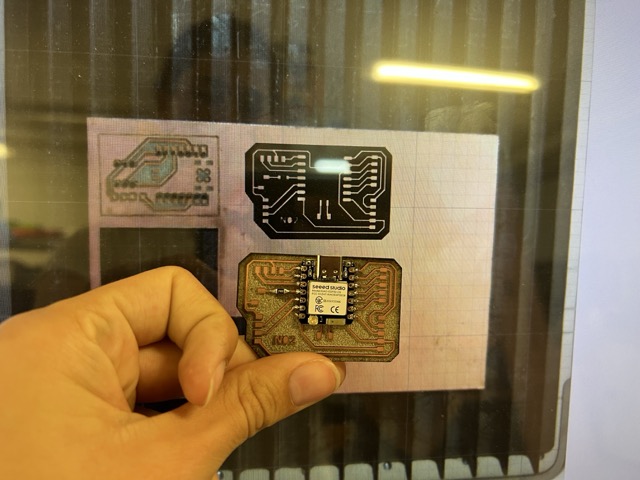
After cutting, I soldered the components. Since I started with the communications section and the pogo pins had not arrived yet, I soldered male pin headers provisionally in their place.
Programming — ENS160 + AHT21 Sensor
This week I started programming my new ENS160 + AHT21 sensor. I used Gemini as my teacher again, specifying in the prompt that I did not want it to write the code or solutions for me. I reviewed the theory and wrote the code myself to test and understand it.
Important — How This Sensor Works
The ENS160 is a MOX-type air quality sensor. It uses an internal resistor that heats up to trigger a chemical reaction with the air, estimating CO₂ levels based on that. Because of this, during the first 3–5 minutes of operation (warm-up), it will output garbage values.
Because the sensor changes its behavior with heat, it comes paired with the AHT21, which measures temperature and humidity to help calibrate the gas sensor.
DATA SHEETS
- ENS160: Mouser → ENS160 Datasheet
- AHT21: AOSONG → AHT21 Datasheet
This was my first written code. It had a lot of mistakes. I wrote some of them down together with the AI corrections — by questioning the errors and understanding them, I moved to the next version.
#include <wire.h>              // wrong: should be Wire.h (capital W)
#include <ScioSense_ENS160.h>
ScioSense_ENS160.h SensorA;  // wrong: don't include .h here
float SensorA = D6;          // wrong: I2C sensors don't get pin assignments
void setup () {
  Serial.begin(11520);       // wrong: should be 115200
  SensorA.begin();
}
void loop () {
  SensorA.geteCO2()          // wrong: must be stored in a variable
}After correcting the mistakes, I wrote this version with my own inline notes:
#include <Wire.h>
#include <ScioSense_ENS160.h>

ScioSense_ENS160 SensorA;

void setup () {
  Serial.begin(115200);
  SensorA.begin();
}

void loop () {
  // geteCO2 comes from the library — "get" retrieves data.
  // Open the variable (box) first, then store the reading inside it.
  int valorCO2 = SensorA.geteCO2();
  Serial.println(valorCO2); // print data to serial monitor
  delay(1000);              // wait 1 second before the next reading
}Since my sensor module includes both sensors, I needed to read the AHT21 first, pass the temperature and humidity to the ENS160, and then get a calibrated gas reading. I found a reference on Instructables — ENS160-AHT21 Sensor for Arduino — and looked only at the libraries used (ScioSense_ENS160.h and Adafruit_AHTX0.h) before writing my own version.
My main error was the loop order — I was reading CO₂ first and humidity second, but it must be the other way around. This is the corrected code:
#include <Wire.h>
#include <ScioSense_ENS160.h>
#include <Adafruit_AHTX0.h>

ScioSense_ENS160 SensorA;
Adafruit_AHTX0 ahtSensor;

void setup () {
  Serial.begin(115200);
  ahtSensor.begin();
  SensorA.begin();
}

void loop () {
  float valorTemperature = ahtSensor.readTemperature();
  float valorHumidity    = ahtSensor.readHumidity(); // must be read BEFORE CO2

  // "set" is like "get" but is used to configure/send values
  SensorA.setTemperatureandHumidity(valorTemp, valorHum);

  // store the compensated CO2 reading
  int valorCO2 = SensorA.geteCO2();
  Serial.println(valorCO2);
  delay(1000);
}Setting Up Arduino IDE for XIAO ESP32-C6
SETUP STEPS
- 01 Connect the XIAO ESP32-C6 via USB.
- 02 Paste the ESP32 board manager URL in Arduino IDE → Settings → Additional Boards Manager URLs.
- 03 Install the Board Manager for the ESP32 family.
- 04 Go to Select Board → Select Other Boards and Port → choose XIAO_ESP32C6 and the correct port.
- 05 Install the required libraries: ENS160 – AdafruitFork and Adafruit AHTX0.
- 06 Make the physical connections between the board and the sensor based on the schematic.
- 07 To enter upload mode: press and hold BOOT → press and release RESET → release BOOT. Then click Upload.
PHYSICAL CONNECTIONS — SENSOR TO ESP32-C6
SDA Sensor → D4 (ESP32-C6)SCL Sensor → D5 (ESP32-C6)VCC Sensor → VCC (ESP32-C6)GND Sensor → GND (ESP32-C6)
Debugging Process
One of my first problems was that the serial monitor was not enabled and nothing appeared no matter what I tried. I uploaded this simple test code to verify it worked — at first nothing came out, but pressing the BOOT button made the message appear.
void setup() {
  Serial.begin(115200);
  delay(100);
  Serial.println("HELLO");
}

void loop() {
  Serial.println("alive");
  delay(1000);
}After fixing the serial monitor, I could connect to the XIAO but still got no sensor data. The issue was the wrong I2C address. I uploaded this scanner code to find which address the device was actually using:
#include <Wire.h>

void setup() {
  Serial.begin(115200);
  delay(2000);
  Serial.println("Scanning I2C...");

  Wire.begin(D4, D5);

  for (byte addr = 1; addr < 127; addr++) {
    Wire.beginTransmission(addr);
    byte error = Wire.endTransmission();

    if (error == 0) {
      Serial.print("Device found at: 0x");
      Serial.println(addr, HEX);
    }
  }
  Serial.println("Scan complete.");
}

void loop() {}Result
The scan returned address 0x53, but the library was looking for the sensor at 0x52 by default. I explicitly declared the correct address in the object constructor and the sensor started working.
Final Working Code
#include <Wire.h>
#include <ScioSense_ENS160.h>
#include <Adafruit_AHTX0.h>

ScioSense_ENS160 SensorA(0x53);  // <-- correct I2C address
Adafruit_AHTX0 ahtSensor;

void setup() {
  Serial.begin(115200);
  delay(2000);
  Serial.println("Starting...");

  Wire.begin(D4, D5);

  if (!ahtSensor.begin()) {
    Serial.println("ERROR: AHT not found");
    while (1);
  }
  Serial.println("AHT OK");

  if (!SensorA.begin()) {
    Serial.println("ERROR: ENS160 not found");
    while (1);
  }
  Serial.println("ENS160 OK");

  SensorA.setMode(ENS160_OPMODE_STD);
  Serial.println("All systems ready");
}

void loop() {
  sensors_event_t boxHumidity, boxTemp;
  ahtSensor.getEvent(&boxHumidity, &boxTemp);

  float valorTemp = boxTemp.temperature;
  float valorHum  = boxHumidity.relative_humidity;

  SensorA.set_envdata210(
    (uint16_t)((valorTemp + 273.15f) * 64.0f),
    (uint16_t)(valorHum * 512.0f)
  );

  if (SensorA.measure(true)) {
    Serial.print("Temp: ");    Serial.print(valorTemp);          Serial.println(" C");
    Serial.print("Humidity: ");Serial.print(valorHum);           Serial.println(" %");
    Serial.print("eCO2: ");    Serial.print(SensorA.geteCO2());  Serial.println(" ppm");
    Serial.print("TVOC: ");    Serial.print(SensorA.getTVOC());  Serial.println(" ppb");
    Serial.println("---");
  } else {
    Serial.println("Waiting for ENS160 reading...");
  }

  delay(1000);
}C++ Mini Dictionary
Key terms and functions used in this code — translated into plain language.
| Term / Command | What it does |
|---|---|
| sensors_event_t | Acts as two special shipping boxes. You hand them to the sensor and it fills them all at once with all the climate data. Example: sensors_event_t boxHumidity, boxTemp; |
| getEvent(&box1, &box2) | Used to collect the information from the boxes. The & symbol tells the board "here is the address of the box — fill it." Example: mySensor.getEvent(&boxHumidity, &boxTemp); |
| geteCO2() | Retrieves the eCO2 reading from the ENS160 library. The get prefix is the library's naming convention for reading data. |
| set_envdata210() | Sends the temperature (in Kelvin × 64) and humidity (× 512) to the ENS160 so it can compensate and calibrate its gas readings. |
| setMode(ENS160_OPMODE_STD) | Activates the sensor's standard operating mode — turns on the internal heaters so gas detection can begin. |
| while(1) | An infinite loop used to halt the program permanently when a critical error is detected (e.g., sensor not found). |
Key Learnings
- Order matters in setup: all programming must follow a logical order for the system to work correctly.
- If the code is not working, the problem might be something outside the program itself — like the I2C address or the serial monitor. I recommend testing those separately with simple dedicated code snippets.
MQTT — Wi-Fi Data Publishing
After confirming that the sensors worked and reviewing the programming fundamentals, I moved directly to MQTT, the protocol that matters most for my final project. I decided to use MQTT because it is the most efficient way to send short messages over Wi-Fi. It is perfect for my project because it allows the microcontroller to publish real-time air quality readings quickly and reliably.
Physical Connections Attempted (I2C)
I connected both I2C lines in parallel on a breadboard. One great feature of I2C is that you can connect multiple devices on the same two wires, you just need to give them different addresses.
I2C BETWEEN BOARDS
SDA RP2350 → SDA ESP32-C6SCL RP2350 → SCL ESP32-C6GND RP2350 → GND ESP32-C6(shared ground is required)
Problem — RP2350 Froze
During I2C experimentation, the RP2350 froze and stopped accepting uploaded code entirely. If your RP2350 ever freezes like this, you can revive it easily: hold down the BOOT button, connect the USB cable to the computer, count five seconds slowly, then release the button (It took me 4 hours to figure that out).
MQTT Architecture
BROKER
The central server that receives and distributes messages. For this week I used the public server at broker.hivemq.com.
PUBLISHER (SENDER)
Responsible for sending data. In my project the XIAO ESP32-C6 is the publisher — it sends eCO2 and TVOC values.
TOPIC
The "address" where data is published — the exact label or channel where the information lives.
Mental Model — Message Flow
- Wi-Fi STA connects → IP address acquired.
- MQTT client starts → connects to the broker.
- On
MQTT_EVENT_CONNECTED: subscribe + publish "online" status. - On
MQTT_EVENT_DATA: parse command topic/payload → act → publish acknowledgment/status. - Periodically publish telemetry (timer/task).
First Step — Install PubSubClient
Download the PubSubClient.h library, it handles the entire MQTT protocol. The WiFi.h library comes pre-installed in the ESP32 core, so no separate installation is needed.
MQTT Code — Full Firmware
#include <WiFi.h>
#include <PubSubClient.h>
#include <Wire.h>
#include <ScioSense_ENS160.h>
#include <Adafruit_AHTX0.h>

// --- Wi-Fi Credentials ---
const char* ssid     = "YOUR_SSID";
const char* password = "YOUR_PASSWORD";

// --- MQTT Configuration ---
const char* mqtt_server      = "broker.hivemq.com";
const char* topic_eco2        = "nicole/monitor/eco2";
const char* topic_tvoc        = "nicole/monitor/tvoc";
const char* topic_temperature = "nicole/monitor/temperatura";

WiFiClient   espClient;
PubSubClient client(espClient);

// --- Sensor Objects ---
ScioSense_ENS160 ens160(0x53);
Adafruit_AHTX0   aht21;

// --- Wi-Fi Setup ---
void setup_wifi() {
  delay(10);
  Serial.print("\nConnecting to WiFi...");
  WiFi.begin(ssid, password);
  while (WiFi.status() != WL_CONNECTED) {
    delay(500);
    Serial.print(".");
  }
  Serial.println("\nWiFi connected!");
}

// --- MQTT Reconnect ---
void reconnect() {
  while (!client.connected()) {
    Serial.print("Attempting MQTT connection...");
    String clientId = "XIAO_C6_Nicole_";
    clientId += String(random(0xffff), HEX);
    if (client.connect(clientId.c_str())) {
      Serial.println("Connected to Broker!");
    } else {
      Serial.print("Failed, rc=");
      Serial.print(client.state());
      Serial.println(" retrying in 5 seconds");
      delay(5000);
    }
  }
}

void setup() {
  Serial.begin(115200);
  delay(2000);
  Serial.println("=== MainESP-C6 Starting ===");

  setup_wifi();
  client.setServer(mqtt_server, 1883);

  Wire.begin(D4, D5);

  if (!aht21.begin()) {
    Serial.println("[ERROR] AHT21 not found.");
    while (1) delay(500);
  }

  if (!ens160.begin()) {
    Serial.println("[ERROR] ENS160 not found.");
    while (1) delay(500);
  }

  ens160.setMode(ENS160_OPMODE_STD);
  Serial.println("=== System ready. Reading data... ===\n");
}

void loop() {
  if (!client.connected()) reconnect();
  client.loop();

  sensors_event_t evtHum, evtTemp;
  aht21.getEvent(&evtHum, &evtTemp);

  float temperature = evtTemp.temperature;
  float humidity    = 50.0; // placeholder

  ens160.set_envdata210(
    (uint16_t)((temperature + 273.15f) * 64.0f),
    (uint16_t)(humidity * 512.0f)
  );

  if (ens160.measure(true)) {
    uint16_t eco2 = ens160.geteCO2();
    uint16_t tvoc = ens160.getTVOC();

    Serial.print("Temp:");  Serial.print(temperature); Serial.println("C");
    Serial.print("eCO2: "); Serial.print(eco2);         Serial.println(" ppm");
    Serial.print("TVOC: "); Serial.print(tvoc);         Serial.println(" ppb");

    char eco2String[10], tvocString[10], temperatureString[10];
    sprintf(eco2String,         "%d",   eco2);
    sprintf(tvocString,         "%d",   tvoc);
    sprintf(temperatureString,  "%.1f", temperature);

    client.publish(topic_eco2,        eco2String);
    client.publish(topic_tvoc,        tvocString);
    client.publish(topic_temperature, temperatureString);

    Serial.println("-> Data published to HiveMQ");
  }

  delay(2000);
}Explanation
Libraries
WiFi.h— Gives the microcontroller access to your local Wi-Fi network.PubSubClient.h— Handles all MQTT message sending and receiving.Wire.h— Required to build the physical I2C connection with the hardware.ScioSense_ENS160.h— Controls the gas sensor to extract eCO2 and TVOC values.Adafruit_AHTX0.h— Reads temperature and humidity data.
After the libraries, the code defines the router credentials, the public broker address, and the specific topics where the dashboard will listen.
Network Configuration
setup_wifi()— Starts the connection process to your home router.reconnect()— Keeps the system online. If the internet drops, it retries every 5 seconds. It also generates a unique Client ID to avoid conflicts with other users sharing the public HiveMQ server.
Setup Block
Wire.begin(D4, D5)— Maps I2C communication to pins D4 (SDA) and D5 (SCL) of the XIAO ESP32-C6.aht21.begin() / ens160.begin()— Wakes up both sensors. If either fails, the program halts in an infinite loop to prevent crashes.ens160.setMode(ENS160_OPMODE_STD)— Activates standard mode — turns on the internal heaters to start detecting gases.client.setServer(mqtt_server, 1883)— Tells the board the exact destination and port for data delivery.
Loop Block
set_envdata210()— Converts temperature to Kelvin (×64) and humidity (×512) — the exact format the ENS160 needs to calibrate its gas readings.sprintf()— Converts raw sensor numbers into text strings for publishing. The%.1ftrick limits temperature to one decimal place (e.g. 25.3).client.publish()— Sends the final text values over the internet to their specific MQTT topics.
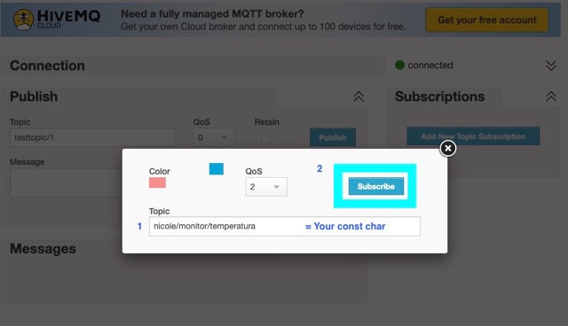
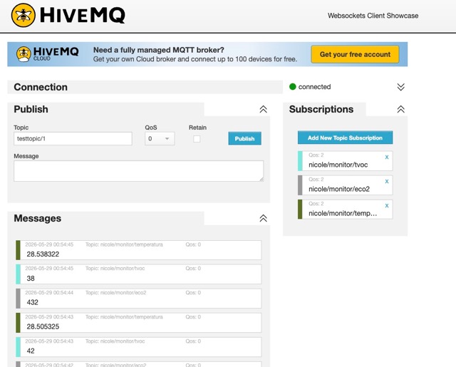
Verifying Data in the Browser — HiveMQ WebSocket Client
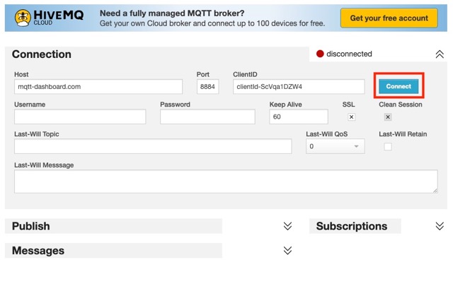
To confirm that the data was actually reaching the server, I used HiveMQ's public WebSocket client in the browser to subscribe to the topics and monitor the live data flow.
HOW TO CHECK YOUR TOPIC DATA
- 01 Go to hivemq.com/demos/websocket-client and click Connect. Do not change any settings.
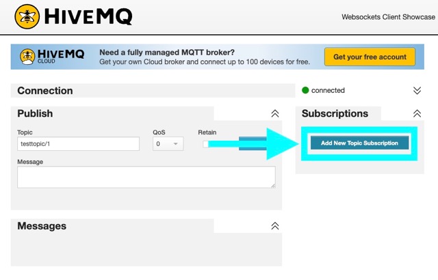
- 02 Click "Add New Topic Subscription."
-
03
Add the topics exactly as you defined them in your code with
const char*. - 04 You should see all the data coming in from the topics you subscribed to.
Problem — Data Type Mismatch with sprintf
There was a clash between data types when using sprintf for the temperature value: the system expected an integer (%d) but received a float with decimal places. I fixed it by changing the format to %f first, then refined it to %.1f to show only one decimal (e.g., 25.3).
Web Interface Test
To see if I would be able to use this for my final interface I asked Gemini to make the control interface. It worked really well and I found it very interesting how it uses JavaScript to connect to the WebSocket Broker and update everything. This is the page, it is in my current Fab Academy repository. To see the code just go to the site, right-click and click on View Page Source. This is a video of how everything works together:
Testing the Page as a Publisher — ESP Receiver
I also tested having the web page itself send information to an ESP acting as a receiver. For this, I borrowed an ESP from one of my classmates. Below is a diagram showing how the communication works, followed by the full receiver code loaded onto the other ESP.

Receiver Code — XIAO ESP32-C6 NeoPixel
This code runs on the receiver ESP. It subscribes to the nicole/monitor/control topic and turns the NeoPixel ring ON or OFF based on the message it receives from the web page.
#include <WiFi.h>
#include <PubSubClient.h>
#include <Adafruit_NeoPixel.h>

// --- Wi-Fi Credentials ---
const char* ssid     = "iPhone de Nicole 13";
const char* password = "laFldsmdfr";

// --- MQTT Configuration ---
const char* mqtt_server   = "broker.hivemq.com";
const char* topic_control = "nicole/monitor/control";

// --- NeoPixel Configuration ---
#define NEOPIXEL_PIN  D0
#define NUM_PIXELS    12

WiFiClient   espClient;
PubSubClient client(espClient);
Adafruit_NeoPixel ring(NUM_PIXELS, NEOPIXEL_PIN,
                       NEO_GRB + NEO_KHZ800);

// --- Wi-Fi Setup ---
void setup_wifi() {
  delay(10);
  Serial.print("\nConnecting to WiFi...");
  WiFi.begin(ssid, password);
  while (WiFi.status() != WL_CONNECTED) {
    delay(500);
    Serial.print(".");
  }
  Serial.println("\nWiFi connected!");
}

// --- NeoPixel ON ---
void ringOn() {
  for (int i = 0; i < NUM_PIXELS; i++) {
    ring.setPixelColor(i, ring.Color(24, 188, 156));
  }
  ring.show();
  Serial.println("[NeoPixel] Ring: ON");
}

// --- NeoPixel OFF ---
void ringOff() {
  ring.clear();
  ring.show();
  Serial.println("[NeoPixel] Ring: OFF");
}

// --- MQTT Callback ---
void callback(char* topic, byte* payload,
              unsigned int length) {
  String message = "";
  for (unsigned int i = 0; i < length; i++) {
    message += (char)payload[i];
  }
  Serial.print("Message received: ");
  Serial.println(message);

  if (message == "ON") {
    ringOn();
  } else if (message == "OFF") {
    ringOff();
  }
}

// --- MQTT Reconnect ---
void reconnect() {
  while (!client.connected()) {
    Serial.print("Attempting MQTT connection...");
    String clientId = "XIAO_C6_Receiver_";
    clientId += String(random(0xffff), HEX);
    if (client.connect(clientId.c_str())) {
      Serial.println("Connected to Broker!");
      client.subscribe(topic_control);
    } else {
      Serial.print("Failed, rc=");
      Serial.print(client.state());
      Serial.println(" retrying in 5 seconds");
      delay(5000);
    }
  }
}

void setup() {
  Serial.begin(115200);
  delay(2000);
  Serial.println("=== XIAO C6 NeoPixel Receiver ===");

  ring.begin();
  ring.setBrightness(150);
  ring.clear();
  ring.show();

  setup_wifi();
  client.setServer(mqtt_server, 1883);
  client.setCallback(callback);

  Serial.println("=== Ready. Waiting for commands ===");
}

void loop() {
  if (!client.connected()) reconnect();
  client.loop();
}Explanation
Libraries
WiFi.h— Connects the microcontroller to the Wi-Fi network.PubSubClient.h— Handles MQTT message reception and topic subscription.Adafruit_NeoPixel.h— Controls the NeoPixel LED ring connected to pin D0.
The code also defines the Wi-Fi credentials, the public broker address, and the topic it will listen to for incoming commands.
Helper Functions
ringOn()— Sets all 12 pixels to the dashboard accent color (teal: 24, 188, 156) and callsring.show()to push the update.ringOff()— Clears all pixels and callsring.show()to turn the ring off.setup_wifi()— Connects to the Wi-Fi network before anything else runs.
MQTT Callback
callback()— Runs automatically every time a message arrives on the subscribed topic. It reads the raw byte payload, builds a string, and callsringOn()orringOff()based on whether the message is "ON" or "OFF".
Setup & Loop
ring.begin() / setBrightness(150)— Initializes the NeoPixel ring and sets its brightness level before any commands arrive.client.setCallback(callback)— Registers the callback function so PubSubClient knows what to run when a message is received.reconnect()— On every connection attempt it also callsclient.subscribe(topic_control)to re-register the subscription.client.loop()— Called every loop cycle to maintain the broker connection and check for new incoming messages.
You can interact with the live control interface here — it connects directly to the HiveMQ broker and sends ON/OFF commands to the receiver ESP in real time.
Visit Live Page →Final Demo Video
Final Result
What Was Achieved This Week
This week I used the I2C protocol to validate readings from the ENS160 + AHT21 sensors on a single data bus. For the final project architecture, I tested a communication network that will rely exclusively on the MQTT protocol over Wi-Fi. By connecting the microcontroller to the wireless network via MQTT, the air quality monitor will be able to transmit eCO2 and TVOC in real time, enabling the system to respond to environmental changes intelligently, remotely, and automatically.
Bonus — How I Revived the RP2350
This week I accidentally killed and then revived my RP2350. It stopped accepting uploads entirely after some I2C experimentation and I spent hours trying to fix it. The solution: press and hold BOOT, connect the USB cable, wait 5 seconds, then release the button. The board came back to life immediately. Because of this I ended up using UART communication instead of I2C.
Final PCB